ENGINE PERFORMANCE
3.5L
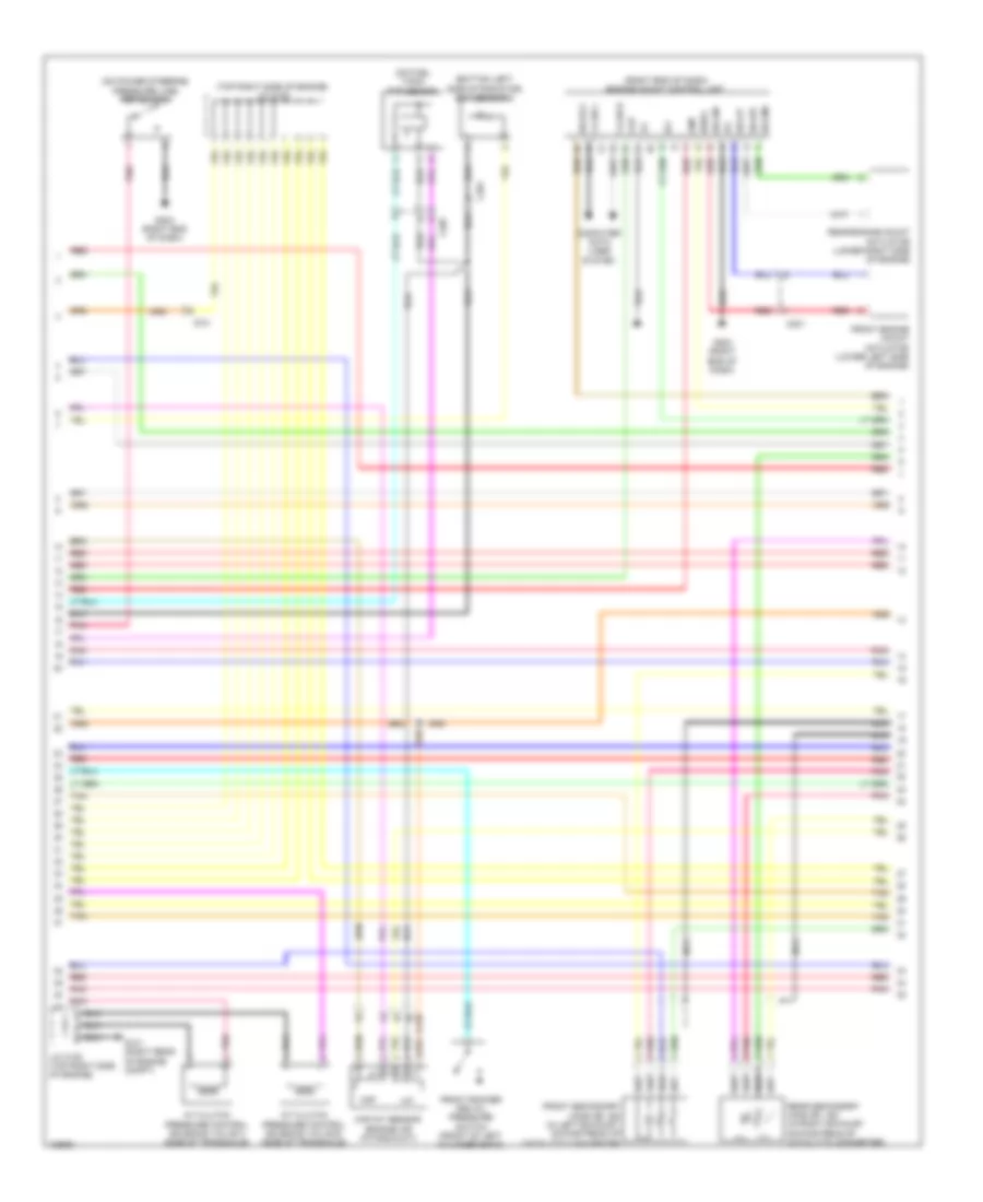
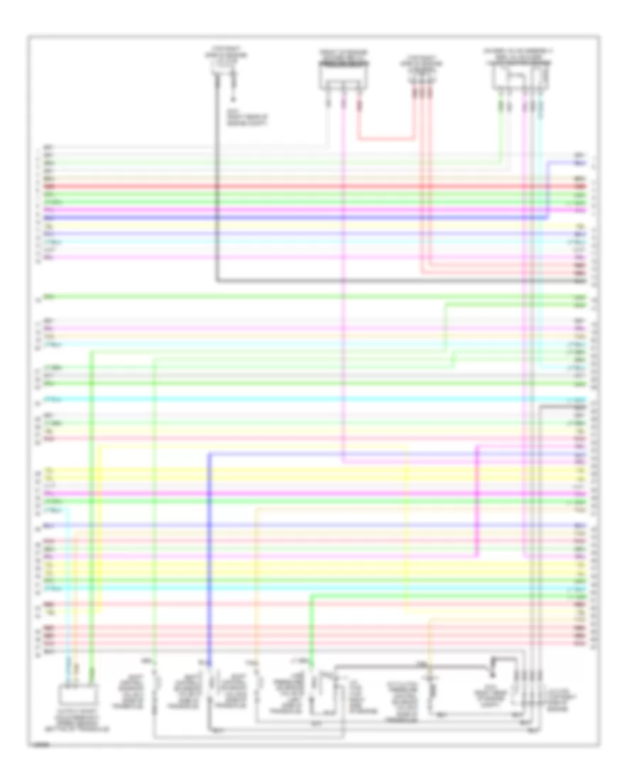
3.5L, Engine Performance Wiring Diagram (1 of 7) for Honda Odyssey EX 2014
 https://portal-diagnostov.com/license.html
Automotive Electricians Portal FZCO
Automotive Electricians Portal FZCO
https://portal-diagnostov.com/license.html
https://portal-diagnostov.com/license.html
Automotive Electricians Portal FZCO
Automotive Electricians Portal FZCO
List of elements for 3.5L, Engine Performance Wiring Diagram (1 of 7) for Honda Odyssey EX 2014:
- (left center of dash) g403
- (left end of dash) g302
- (top of accelerator pedal assembly) app sensor
- A10
- A11
- A12
- A13
- A14
- A15
- A16
- A17
- A18
- A19
- A20
- A21
- A22
- A23
- A24
- A25
- A26
- A27
- A28
- A29
- A30
- A31
- A32
- A33
- A35
- A36
- A37
- A38
- A39
- A40
- A41
- A42
- A43
- A44
- A45
- A46
- A47
- A48
- A49
- Acc
- Air conditioning system
- Anti-theft system
- Apsa
- Apsb
- Atpp
- B10
- B11
- B12
- B13
- B14
- B15
- B16
- B17
- B18
- B19
- B20
- B21
- Bksw
- Bkswnc
- C201
- C205
- C210
- C212
- Ckpout
- Cmpout
- Computer data lines system
- Cooling fans system
- Cruise control system
- Cssama
- Cssamc
- D4 switch
- D4sw
- Ect2
- Eld
- Eld unit
- Etcs control relay
- Etcsrly
- F-can-h
- F-can-l
- Fanh
- Fanl
- Ftp
- Fuse 15a
- G101 (right rear of engine compt)
- Hot at all times
- Hot in on or start
- Igp
- Igpls5
- Igpls6
- Imofpr
- Imtm
- Inj1
- Inj2
- Inj3
- Inj4
- Inj5
- Inj6
- Injectors 1, 2 & 3 (under intake manifold, in right cylinder bank)
- Injectors 4, 5 & 6 (under intake manifold, in left cylinder bank)
- J/c c105 (top right side of engine)
- Lever connector
- Lg3
- Lsb
- Lsc
- Main under-hood fuse box (above transaxle)
- Mcs
- Mrly
- Navigation & sound systems
- Nep a34
- Pcm (right side of engine compt)
- Pg2
- Pgm fi main relay 1
- Pnk
- Power distribution system
- Pspsw
- Red
- S-net 5v
- Scs
- Sensor barometer
- Sg3
- Sg4
- Sg7
- Shift
- Shift interlock system
- Sho2sb2
- Sls
- Starting/ charging system
- Starting/charging & anti-theft systems
- Starting/charging & shift interlock systems
- Starting/charging system
- Strld
- Strly
- Sts
- Subrly
- Tan
- Tpsa
- Under-hood relay fuse/box (right rear of engine compt)
- Vbsol
- Vbsol2
- Vcc3
- Vcc4
- Vcc5
- Vcc7
- Vcentb1
- Vcmswc
- Vg+
- Vg-
- Vsb1
- Vsb2
- Vssout
- Vsv
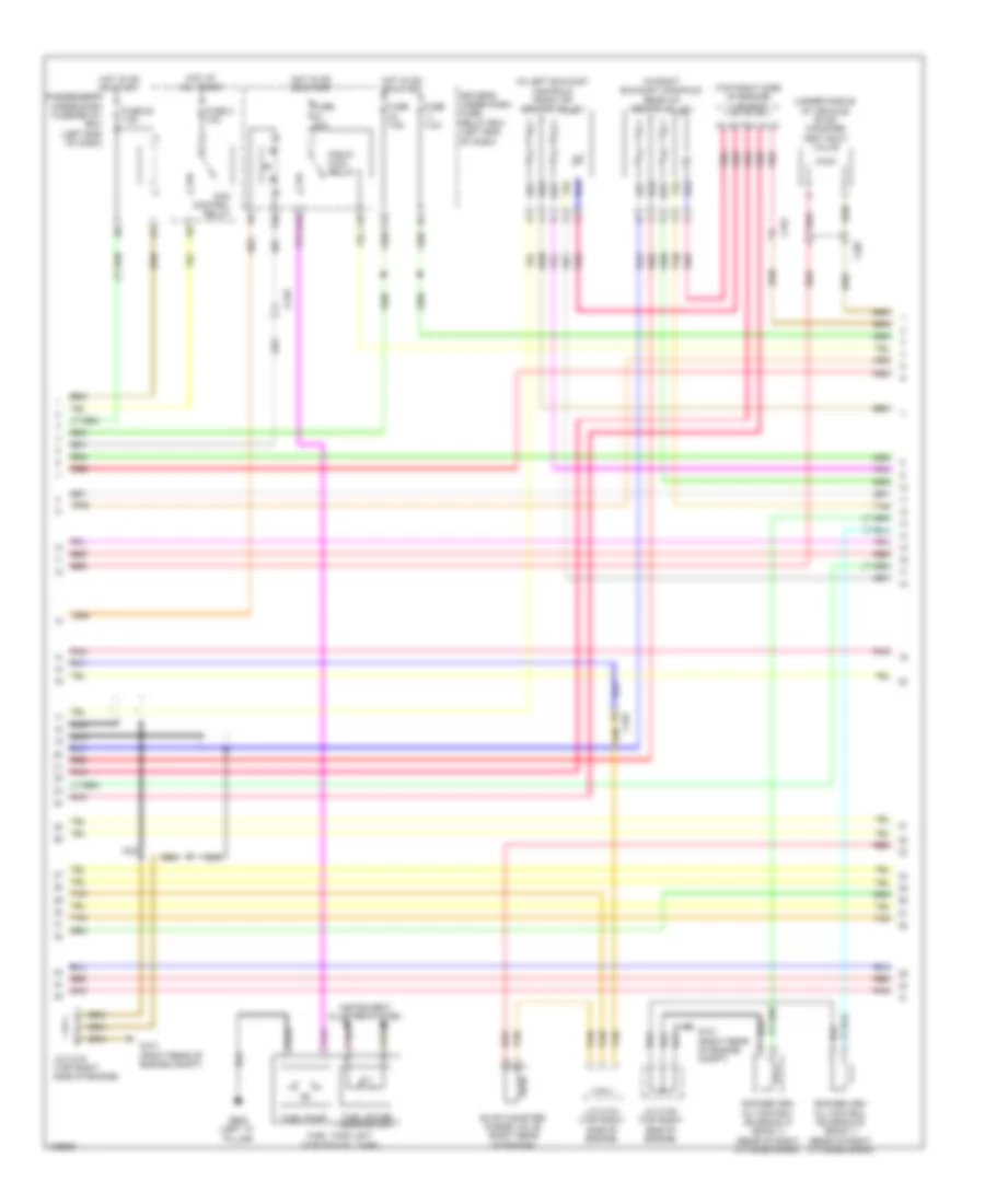
3.5L, Engine Performance Wiring Diagram (2 of 7) for Honda Odyssey EX 2014
List of elements for 3.5L, Engine Performance Wiring Diagram (2 of 7) for Honda Odyssey EX 2014:
- (bottom left side of radiator) ect sensor 2
- (on fuel tank) ftp sensor
- (on power steering pressure line) psp switch
- (right end of dash) engine mount control unit
- (top right side of engine) j/c c102
- A/t clutch pressure control solenoid valve b (side of transaxle)
- A/t clutch pressure control solenoid valve c (side of transaxle)
- C101
- C201
- C207
- C210
- Ckp
- Cmp
- Computer data lines system
- F-can h
- F-can l
- Front engine mount actuator (lower left side of engine)
- Front rocker arm oil pressure switch (front of left cylinder bank)
- Front secondary ho2s (b2, s2) (in left exhaust, downstream of catalytic converter)
- G101 (right rear of engine compt)
- G204 (right end of dash)
- Iat
- Ig1
- Igsol
- J/c c105 (top right side of engine)
- Maf
- Maf/iat sensor (engine air intake duct)
- Nca
- Pnk
- Rear engine mount actuator (lower right side of engine)
- Rear secondary ho2s (b1, s2) (in right exhaust, downstream of catalytic converter)
- Red
- Solfm
- Solfp
- Solrly
- Solrm
- Solrp
- Tan
3.5L, Engine Performance Wiring Diagram (3 of 7) for Honda Odyssey EX 2014
List of elements for 3.5L, Engine Performance Wiring Diagram (3 of 7) for Honda Odyssey EX 2014:
- (in left exhaust manifold) front a/f sensor (b2, s1)
- (in right exhaust manifold) rear a/f sensor (b1, s1)
- (top right side of engine) j/c c104
- (under middle of vehicle) evap canister vent shut valve
- Acm control relay
- C101
- C207
- C210
- Driver's under dash fuse/ relay box (left end of dash)
- E16
- Evap canister purge valve (right rear of engine)
- F10
- F20
- F21
- Fuel gauge sending unit
- Fuel pump
- Fuel tank unit (top of fuel tank)
- Fuse 20 7.5a
- Fuse 20a
- Fuse 3 10a
- Fuse 7.5a
- G101 (right rear of engine compt)
- G602 (left "c" pillar)
- Hot at all times
- Hot in on or start
- Instrument cluster system
- J/c c103 (top right side of engine)
- J/c c104 (top right side of engine)
- J/c c105 (top right side of engine)
- Nca
- Passenger's under-dash fuse/relay box (left end of dash)
- Pgm-fi main relay 2
- Pnk
- Red
- Rocker arm oil control solenoid a (bank 1) (rear of right cylinder bank)
- Rocker arm oil control solenoid b (bank 1) (rear of right cylinder bank)
- Tan
3.5L, Engine Performance Wiring Diagram (4 of 7) for Honda Odyssey EX 2014
List of elements for 3.5L, Engine Performance Wiring Diagram (4 of 7) for Honda Odyssey EX 2014:
- (upper left end of dash) g401
- C101
- C212
- Computer data lines system
- Control circuits
- Fast controller area network transceiver
- Fuse 11 15a
- Fuse 28 7.5a
- Fuse 8 15a
- G101 (right rear of engine compt)
- Gauge control module
- Hot at all times
- Icm
- Ignition coil relay
- Ignition coils (1, 2 & 3: top of right cylinder bank) (4, 5 & 6: top of left cylinder bank)
- J/c c102 (top right side of engine)
- J/c c104 (top right side of engine)
- J/c c105 (top right side of engine)
- Mil ind
- Pgm fi sub relay
- Pnk
- Radiator fan relay
- Radiator fan relay diode
- Rear rocker arm oil pressure switch (rear of right cylinder bank)
- Red
- Tan
- Under- hood fuse/ relay box (right rear of engine compt)
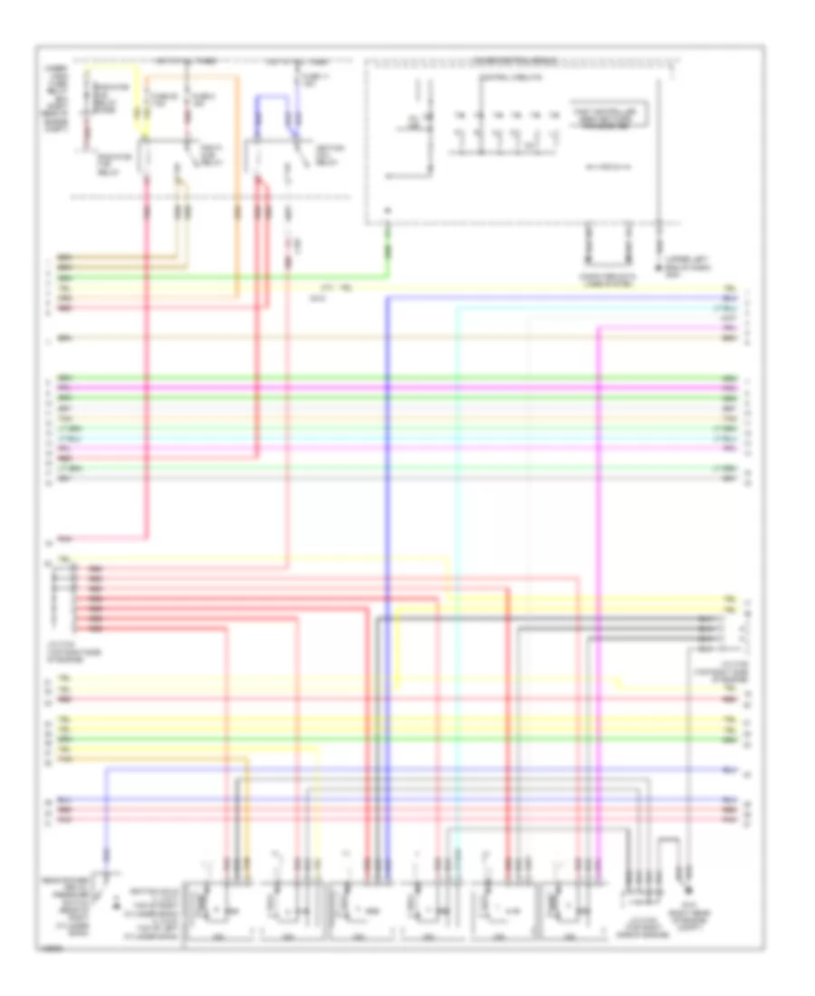
3.5L, Engine Performance Wiring Diagram (5 of 7) for Honda Odyssey EX 2014
List of elements for 3.5L, Engine Performance Wiring Diagram (5 of 7) for Honda Odyssey EX 2014:
- (bottom of transaxle) atf temperature sensor
- (left side of transaxle) input shaft (mainshaft) speed sensor
- (top rear of engine) ect sensor 1
- (top right side of engine) j/c c104
- (top right side of engine) j/c c105
- 2nd clutch transmission fluid pressure switch a (left side of transaxle)
- 3rd clutch transmission fluid pressure switch b (top of transaxle)
- C101
- J/c c105 (top right side of engine)
- Map sensor (right rear of engine)
- Pnk
- Red
- Starting/ charging system
- Tan
- Transmission range switch (top of transaxle)
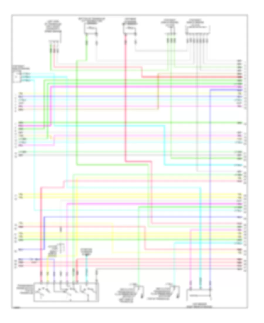
3.5L, Engine Performance Wiring Diagram (6 of 7) for Honda Odyssey EX 2014
List of elements for 3.5L, Engine Performance Wiring Diagram (6 of 7) for Honda Odyssey EX 2014:
- (front of engine) rocker arm oil pressure sensor
- (on egr valve assembly) egr valve & egr valve position sensor
- (top right side of engine) j/c c103
- (top right side of engine) j/c c105
- A/t clutch pressure control solenoid valve d (side of transaxle)
- G101 (right rear of engine compt)
- J/c c102 (top right side of engine)
- J/c c105 (top right side of engine)
- Line pressure solenoid valve a (left side of transaxle)
- Output shaft (countershaft) speed sensor (bottom of transaxle)
- Pnk
- Red
- Shift control solenoid valve a (side of transaxle)
- Shift control solenoid valve b (side of transaxle)
- Shift control solenoid valve c (side of transaxle)
- Tan
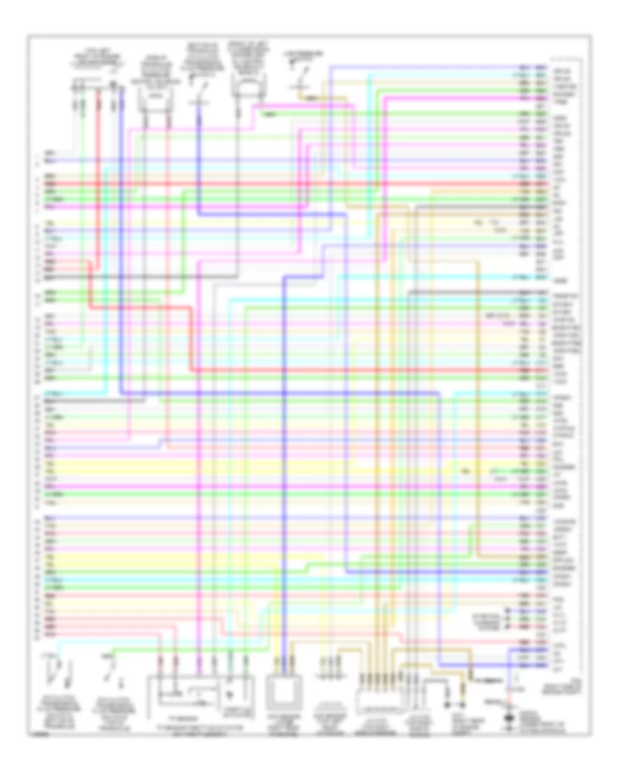
3.5L, Engine Performance Wiring Diagram (7 of 7) for Honda Odyssey EX 2014
List of elements for 3.5L, Engine Performance Wiring Diagram (7 of 7) for Honda Odyssey EX 2014:
- (bottom of transaxle) 4th clutch transmission fluid pressure switch c
- (front of left cylinder bank) rocker arm oil control solenoid a (bank 2)
- (side of transaxle) a/t clutch pressure control solenoid valve a
- (top left front of engine) imt actuator
- 5th clutch transmission fluid pressure switch d (bottom of transaxle)
- 6th clutch transmission fluid pressure switch e (top of transaxle)
- Afshtcb1
- Afshtcb2
- Altc
- Altf
- Altl
- Atpd
- Atpfwd
- Atpl
- Atpn
- Atpr
- Atprvs
- B22
- B23
- B24
- B25
- B26
- B27
- B28
- B29
- B30
- B31
- B32
- B33
- B34
- B35
- B36
- B37
- B38
- B39
- B40
- B41
- B42
- B43
- B44
- B45
- B46
- B47
- B48
- B49
- C10
- C101
- C106
- C11
- C12
- C13
- C14
- C15
- C16
- C17
- C18
- C19
- C20
- C21
- C22
- C23
- C24
- C25
- C26
- C27
- C28
- C29
- C30
- C31
- C32
- C33
- C34
- C35
- C36
- C37
- C38
- C39
- C40
- C41
- C42
- C43
- C44
- C45
- C46
- C47
- C48
- C49
- Ckp
- Ckp sensor (lower right rear of engine)
- Cmp
- Cmp sensor (top left front of engine)
- Cssa
- Cssb
- Cssc
- Ect1
- Egr
- Egrp
- Etcsm+
- Etcsm-
- G101 (right rear of engine compt)
- Iat
- Ig1
- Ig1etcs
- Igpls1
- Igpls2
- Igpls3
- Igpls4
- Imt+
- Imt-
- Ipb1
- Ipb2
- J/c c102 (top right side of engine)
- J/c c103 (top right side of engine)
- Knock sensor (under front of intake manifold)
- Lg1
- Lg2
- Line pressure switch
- Lsa
- Lsd
- Map
- Nca
- Op2sw
- Op3sw
- Op4sw
- Op5sw
- Op6sw
- Pcm (right side of engine compt)
- Pcs
- Pg1
- Pgmetcs
- Pla
- Pnk
- Poil
- Red
- Sg1
- Sg2
- Sg5
- Sg6
- Sha
- Shb
- Shc
- Sho2sb1
- So2sgb1
- So2sgb2
- So2shtcb1
- So2shtcb2
- Starting/ charging system
- Tan
- Tatf
- Throttle actuator
- Tp sensor
- Tp sensor/throttle actuator (on throttle body)
- Tpsb
- Vcc1
- Vcc2
- Vcc6
- Vcentb2
- Vcmswb

 Čeština
 Dansk
Dansk Deutsch
 Ελληνικά
 English
 Español
 Suomi
Suomi Français
 Français
 עברית
עברית Hrvatski
 Magyar
 Italiano
 日本語
日本語 한국어
한국어 Nederlands
 Polski
 Português
 Português
 Română
 Русский
 Slovenčina
 Slovenščina
 Svenska
 Türkçe
 中文 (中国)