ENGINE PERFORMANCE
3.5L
3.5L, Engine Performance Wiring Diagram (1 of 5) for Honda Pilot EX 2004
 https://portal-diagnostov.com/license.html
Automotive Electricians Portal FZCO
Automotive Electricians Portal FZCO
https://portal-diagnostov.com/license.html
https://portal-diagnostov.com/license.html
Automotive Electricians Portal FZCO
Automotive Electricians Portal FZCO
List of elements for 3.5L, Engine Performance Wiring Diagram (1 of 5) for Honda Pilot EX 2004:
- 2wbs
- 4th clutch transmission fluid pressure switch (on transaxle end cover)
- A/t clutch pressure control solenoid valve a (on trans- mission housing)
- A/t clutch pressure control solenoid valve b (on trans- mission housing)
- A/t clutch pressure control solenoid valve c (on trans- mission housing)
- A/t temp indicator
- A10
- A11
- A12
- A13
- A14
- A15
- A16
- A17
- A18
- A19
- A20
- A21
- A22
- A23
- A24
- A25
- A26
- A27
- A28
- A29
- A30
- A31
- A32
- Acc
- Acs
- Afsdl
- Air conditioning system
- Atfind
- Atpnp
- B10
- B11
- B12
- B13
- B14
- B15
- B16
- B17
- B18
- B19
- B20
- B21
- B22
- B23
- B24
- B25
- Bksw
- C11
- Ccs
- Cooling fans system
- Cruise control system
- Dind
- Driver's underdash fuse/relay box (behind left end of dash)
- Ect out
- Egr
- Eld
- Fanc
- Fasdl
- Ftp
- Fuse 15a
- Fuse 7.5a
- G101 (at left rear of engine)
- Gauge assembly
- Hot at all times
- Hot in on or start
- Hot w/ engine cranking
- Iac valve (under throttle body assembly)
- Iacv
- Igp1
- Igp2
- Ilu
- Imofpr
- Inj1
- Inj2
- Inj3
- Inj4
- Inj5
- Inj6
- J/c c104 (at left side of engine compt)
- J/c c105 (at center of engine compt)
- J/c c106 (at center of engine compt)
- K-line
- Lg1
- Lg2
- Lsa+
- Lsa-
- Lsb+
- Lsb-
- Lsc+
- Lsc-
- Mil
- Nep
- Op4sw
- Passenger's underdash fuse/relay box
- Pcs
- Pg1
- Pg2
- Pgm-fi main relay
- Pnk
- Powertrain control (pcm) module (behind center of dash)
- Pspsw
- Red
- Scs
- Shift interlock system
- Sho2s
- So2shtc
- Stsw
- Underhood fuse/relay box (at right side of engine compt)
- Vbu
- Vssout
- Vsv
- Vtec solenoid valve (at front of engine, on oil pump housing extension)
- Vts
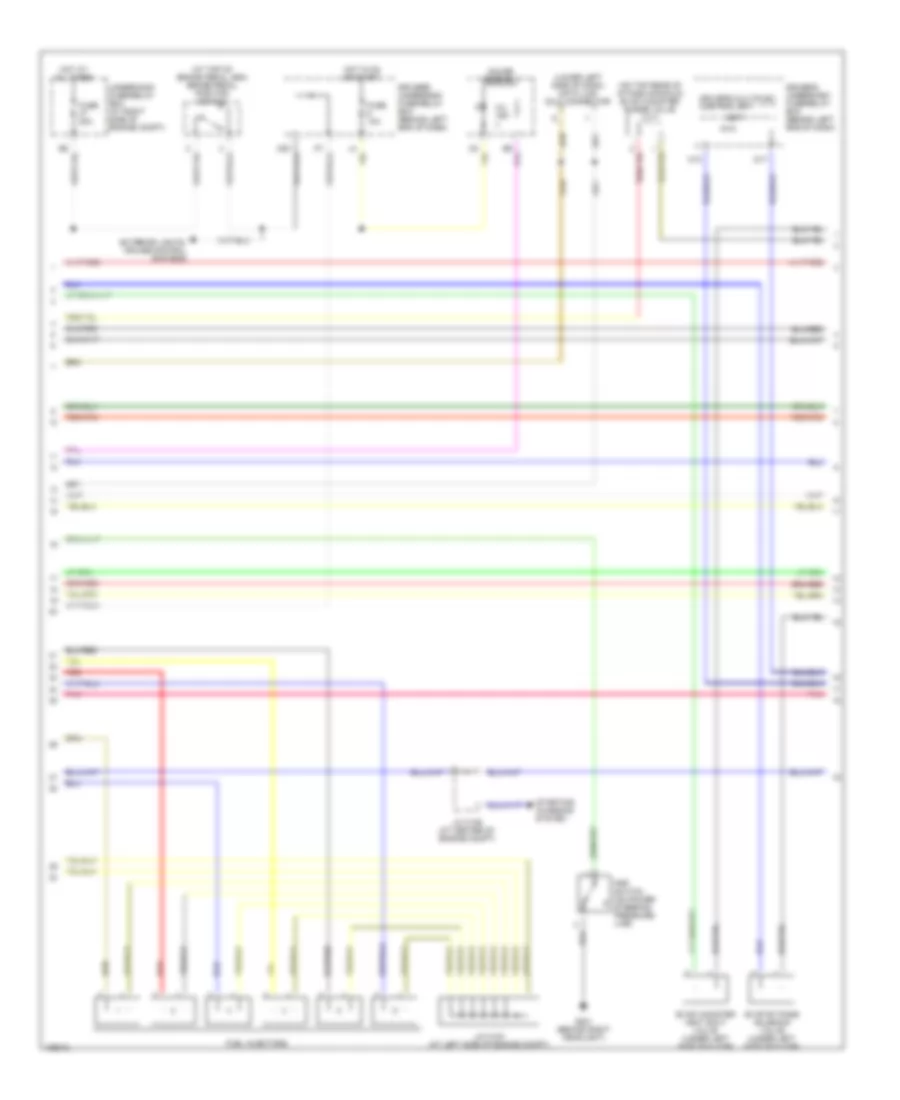
3.5L, Engine Performance Wiring Diagram (2 of 5) for Honda Pilot EX 2004
List of elements for 3.5L, Engine Performance Wiring Diagram (2 of 5) for Honda Pilot EX 2004:
- (at top of brake pedal arm) brake pedal position switch
- (lower left side of dash) data link (dlc) connector
- (on top rear of intake manifold) evap canister purge valve
- At-p
- D17
- Driver's multiplex control unit
- Driver's underdash fuse/relay box (behind left end of dash)
- Evap by-pass solenoid valve (under left side of floor)
- Evap canister vent shut valve (under left side of floor)
- Exterior lights, cruise control systems
- Fuel injectors
- Fuse 10a
- Fuse 20a
- G201 (behind right headlight)
- Gauge assembly
- Hot at all times
- Hot in on or start
- J/c c103 (at left side of engine compt)
- J/c c106 (at center of engine compt)
- K10
- Mil ind
- Pnk
- Psp switch (on power steering pressure line)
- Red
- Starting/ charging system
- Underhood fuse/relay box (at right side of engine compt)
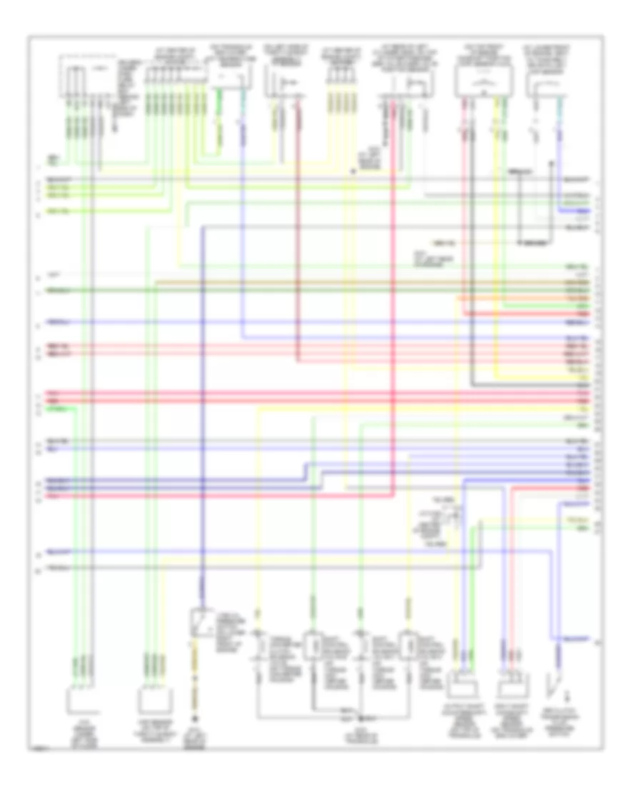
3.5L, Engine Performance Wiring Diagram (3 of 5) for Honda Pilot EX 2004
List of elements for 3.5L, Engine Performance Wiring Diagram (3 of 5) for Honda Pilot EX 2004:
- (at center of engine compt)
- (at center of engine compt) j/c c105
- (at rear of engine, on top of water passage) ect sensor
- (ex, ex-l)
- (not used)
- (on exhaust pipe, upstream of three-way catalytic converter) primary (ho2s) heated oxygen sensor
- (on rear intake manifold chamber) iat sensor
- (on three-way catalytic converter) secondary (ho2s) heated oxygen sensor
- A25
- A29
- B10
- B22
- Braided
- Climate control unit
- Driver's underdash fuse/relay box (behind left end of dash)
- Ect
- Eld unit (in underhood fuse/relay box)
- Fuel gauge send- ing unit
- Fuel ind
- Fuel pump
- Fuel tank unit (under second row seat, below floor access panel)
- Fuse 15a
- G101 (at left rear of engine)
- G201 (behind right headlight)
- G502 (behind left side of dash)
- G601 (below left front seat)
- Gauge assembly
- H12
- Hot in on or start
- Immob
- Immobilizer control unit receiver (in steering column, on ignition key cylinder)
- J/c c105
- Knock sensor (on top of engine block, under intake manifold)
- Passenger's underdash fuse/relay box
- Pnk
- Red
- Tach
- Test tachometer connector (at left side of engine compt)
- Vtm-4 control unit (at left side of cargo area, behind rear side trim panel)
3.5L, Engine Performance Wiring Diagram (4 of 5) for Honda Pilot EX 2004
List of elements for 3.5L, Engine Performance Wiring Diagram (4 of 5) for Honda Pilot EX 2004:
- (at center of engine compt) j/c c105
- (at center of engine compt) j/c c105 j/c c105
- (at lower front of engine, next to timing belt drive pulley) ckp sensor
- (at rear of left cylinder head, on top of water passage) egr valve & egr valve position sensor
- (on left side of throttle body assembly) tp sensor
- (on top front of engine) camshaft position (cmp) sensor a & b
- (on torque con- verter housing)
- (on transaxle end cover) atf temperature sensor
- 3rd clutch transmission fluid pressure switch
- Braided
- D14
- Driver's under- dash fuse/ relay box (behind left (not used) end of dash)
- Ftp sensor (under left side of floor)
- G101 (at left rear of engine)
- G151 (at rear of transaxle)
- Input shaft (mainshaft) speed sensor (on transaxle end cover)
- J/c c106 (at center of engine compt)
- J17
- Map sensor (on top of throttle body assembly)
- Output shaft (countershaft) speed sensor (on top of transaxle)
- Pnk
- Red
- Shift control solenoid valve a
- Shift control solenoid valve b
- Shift control solenoid valve c
- Torque converter clutch solenoid valve (on torque converter housing)
- Vtec oil pressure switch (on lower right front of engine)
3.5L, Engine Performance Wiring Diagram (5 of 5) for Honda Pilot EX 2004
List of elements for 3.5L, Engine Performance Wiring Diagram (5 of 5) for Honda Pilot EX 2004:
- (at left side of engine compt) j/c c104
- (at right front of engine, near power steering pump)
- (behind
- (middle of engine compt) ignition coil 1
- (middle of engine compt) ignition coil 2
- (middle of engine compt) ignition coil 3
- (middle of engine compt) ignition coil 4
- (middle of engine compt) ignition coil 5
- (middle of engine compt) ignition coil 6
- A13
- Altc
- Altf
- Atft
- Atp1
- Atp2
- Atpd
- Atpd3
- Atpp
- Atpr
- C10
- C11
- C12
- C13
- C14
- C15
- C16
- C17
- C18
- C19
- C20
- C21
- C22
- C23
- C24
- C25
- C26
- C27
- C28
- C29
- C30
- C31
- Ckp+
- Ckp-
- Cmp a+
- Cmp a-
- Cmp b+
- Cmp b-
- Cpu
- Cruise control system
- D10
- D11
- D12
- D13
- D14
- D15
- D16
- Dimming circuit
- Driver's under- dash fuse/ relay box (behind left end of dash)
- E10
- E11
- E12
- E13
- E14
- E15
- E16
- E17
- E18
- E19
- E20
- Ect
- Egrp
- Flvl
- Fuse 15a
- G101 (at left rear of engine)
- G102
- G502
- Gauge assembly
- Hot in on or start
- Iat
- Icm
- Igpls1
- Igpls2
- Igpls3
- Igpls4
- Igpls5
- Igpls6
- Imocd
- Imoen
- Imoind
- J/c c106 (at center of engine compt)
- Left side
- Map
- Ncsg
- Nmsg
- Of dash)
- Op3sw
- Pho2s
- Pnk
- Po2shtc
- Powertrain control (pcm) module (behind center of dash)
- Red
- Sg1
- Sg2
- Sha
- Shb
- Shc
- Starting/ charging system
- Tps
- Transmission range switch (on transaxle end cover)
- Vbsol
- Vcc1
- Vcc2
- Vtpsw

 Čeština
 Dansk
Dansk Deutsch
 Ελληνικά
 English
 Español
 Suomi
Suomi Français
 Français
 עברית
עברית Hrvatski
 Magyar
 Italiano
 日本語
日本語 한국어
한국어 Nederlands
 Polski
 Português
 Português
 Română
 Русский
 Slovenčina
 Slovenščina
 Svenska
 Türkçe
 中文 (中国)