ENGINE PERFORMANCE
1.6L
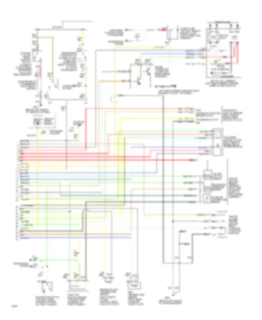
1.6L, Engine Performance Wiring Diagrams, California (1 of 2) for Hyundai Elantra GLS 1994
 https://portal-diagnostov.com/license.html
Automotive Electricians Portal FZCO
Automotive Electricians Portal FZCO
https://portal-diagnostov.com/license.html
https://portal-diagnostov.com/license.html
Automotive Electricians Portal FZCO
Automotive Electricians Portal FZCO
List of elements for 1.6L, Engine Performance Wiring Diagrams, California (1 of 2) for Hyundai Elantra GLS 1994:
- (behind left side of
- (behind left side of i/p, above kick panel)
- (behind left side of i/p, on ecm bracket)
- (center rear of
- (dash fuse box)
- (left side of engine compt,
- A/c relay ctrl
- A/c request in
- A/t
- A/t only
- Acc
- Air conditioning
- Air conditioning system
- Air flow sensor in
- Baro press sensor in
- Battery
- Battery back-up
- C01-4
- C01-5
- C01-6
- Coil control
- Cp sensor in
- Cruise control system
- Dash fuse box (below left side of i/p)
- Data link connector
- Diagnosis
- Diagnosis ctrl signal
- Early prod.
- Ecm control relay
- Ecm relay ctrl
- Ect sensor in
- Egr control solenoid
- Egr solenoid ctrl
- Egr temp sensor in
- Elect spark timing
- Electronic spark timing adjust connector (left side of engine compt, taped to harness)
- Engine compartment relay box (right side of engine compt)
- Engine compt)
- Engine control module (behind left side of i/p)
- Frt htd oxy sensor in
- Fuel inj #1 ctrl
- Fuel inj #2 ctrl
- Fuel inj #3 ctrl
- Fuel inj #4 ctrl
- Fuel injectors
- Fuel pump (inside top left corner of fuel tank,
- Fuel pump ctrl
- Fuel pump inspection connector
- Fuse 10a
- G200
- G202
- G300 (under driver's seat)
- Ground
- Hot at all times
- Hot in on or start
- I/p, above kick panel)
- Iat sensor in
- Idle position sw in
- Idle speed mtr ctrl
- Ig1
- Ignition
- Ignition switch
- Instrument cluster
- Late prod.
- Lock
- M/t
- Malfunction ind ctrl
- Malfunction indicator
- Near filler hose)
- No.1
- No.2
- No.3
- No.4
- P/n (a/t),ground (m/t)
- Power steering pressure switch (left front corner of engine, in power steering oil pump)
- Purge control solenoid
- Purge ctrl solenoid
- Pwr steering press in
- Red
- Red
- Rpm signal in
- Rr htd oxy sensor in
- Sensor ground
- Sensor pwr-5v
- Start
- Starting signal in
- System
- Taped to harness)
- Tdc sensor in
- Tps in
- Transmission system
- Vehicle speed in
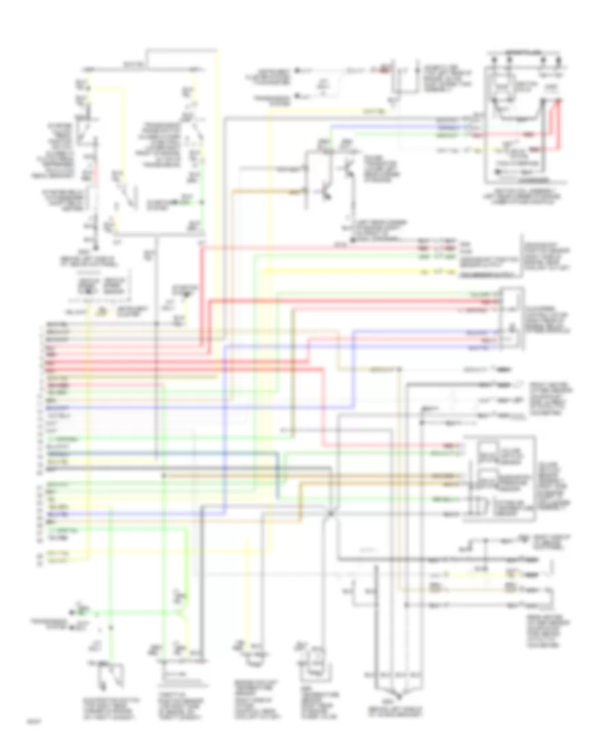
1.6L, Engine Performance Wiring Diagrams, California (2 of 2) for Hyundai Elantra GLS 1994
List of elements for 1.6L, Engine Performance Wiring Diagrams, California (2 of 2) for Hyundai Elantra GLS 1994:
- (behind left side of i/p, above kick panel)
- (behind left side of i/p, on ecm bracket)
- (closed w/ clutch pedal depressed) (on clutch pedal bracket)
- (left rear corner of engine,
- (right side of i/p, behind kick panel)
- (right side of intake manifold, near coolant outlet)
- A/t
- A/t only
- Barometric pressure sensor
- Condenser
- Crankshaft position sensor (right side of engine, near coolant outlet)
- Egr temperature sensor (right rear of engine, in egr valve)
- Engine coolant temperature sensor
- Front heated oxygen sensor (on exhaust pipe, in front of catalytic converter)
- G116
- G200
- G202
- G203
- Idle position switch (top right rear corner of engine, on throttle body)
- Idle speed control motor (right rear of engine, below intake manifold)
- Ignition coil assembly
- Ignition coils
- Instrument cluster
- Instrument cluster system (tachometer)
- Intake air temperature sensor
- M/t
- M/t only
- Nca
- Noise filter (top left rear of engine, on air inlet surge tank assembly)
- On front of cowl top panel)
- Position sensor (top right side of engine, on throttle body)
- Power transistor (lower left rear corner of engine)
- Rear heated oxygen sensor (on exhaust pipe, behind catalytic converter)
- Red
- Red pwr
- Solid state
- Spark plugs
- Starter clutch pedal position switch
- Starter relay (in passenger compt relay center)
- Starting system
- Tach interface
- Throttle
- Transmission range switch (closed in park & neutral) (lower right front of engine, (in top of transmission)
- Transmission system
- Under intake manifold)
- Vehicle speed output
- Vehicle speed sensor
- Volume air flow sensor
- Volume air flow sensor assembly (right side of engine compt, in air cleaner assembly)
1.6L, Engine Performance Wiring Diagrams, Federal (1 of 2) for Hyundai Elantra GLS 1994
List of elements for 1.6L, Engine Performance Wiring Diagrams, Federal (1 of 2) for Hyundai Elantra GLS 1994:
- (behind left side of
- (behind left side of i/p, above kick panel)
- (behind left side of i/p, on ecm bracket)
- (center rear of engine compt)
- (dash fuse box)
- (left front corner
- (left side of engine compt,
- A/c relay ctrl
- A/c request in
- A/t
- A/t only
- Acc
- Air conditioning
- Air flow sensor in
- Baro press sensor in
- Battery
- Battery back-up
- C01-1
- C01-2
- C01-3
- Cluster
- Coil control
- Cp sensor in
- Cruise control system
- Dash fuse box (below left side of i/p)
- Data link connector
- Diagnosis
- Diagnosis ctrl signal
- Early prod.
- Ecm control relay
- Ecm relay ctrl
- Ect sensor in
- Egr control solenoid
- Egr solenoid ctrl
- Egr temp sensor in
- Elect spark timing
- Electronic
- Engine compartment relay box (right side of engine compt)
- Engine control module (behind left side of i/p)
- Fuel inj #1 ctrl
- Fuel inj #2 ctrl
- Fuel inj #3 ctrl
- Fuel inj #4 ctrl
- Fuel injectors
- Fuel pump (inside top left corner of fuel tank,
- Fuel pump ctrl
- Fuel pump inspection connector
- Fuel pump monitor
- Fuse 10a
- G200
- G202
- G300 (under driver's seat)
- Ground
- Hot at all times
- Hot in on or start
- Htd oxy sensor in
- I/p, above kick panel)
- Iat sensor in
- Idle position sw in
- Idle speed mtr ctrl
- Ig1
- Ignition
- Ignition switch
- Instrument
- Late prod.
- Lock
- M/t
- Malfunction ind ctrl
- Malfunction indicator
- Near filler hose)
- No.1
- No.2
- No.3
- No.4
- Of engine, in power
- P/n (a/t),ground (m/t)
- Power steering
- Pressure switch
- Purge control solenoid
- Purge ctrl solenoid
- Pwr steering press in
- Red
- Red
- Rpm signal in
- Sensor ground
- Sensor pwr-5v
- Spark timing adjust connector (left side of engine compt, taped to harness)
- Start
- Starting signal in
- Steering oil pump)
- System
- Taped to harness)
- Tdc sensor in
- Tps in
- Transmission system
- Vehicle speed in
1.6L, Engine Performance Wiring Diagrams, Federal (2 of 2) for Hyundai Elantra GLS 1994
List of elements for 1.6L, Engine Performance Wiring Diagrams, Federal (2 of 2) for Hyundai Elantra GLS 1994:
- (behind left side of i/p, above kick panel)
- (behind left side of i/p, on ecm bracket)
- (closed w/ clutch pedal depressed) (on clutch pedal bracket)
- (left rear corner of engine compt, on front of cowl top panel)
- (left rear corner of engine,
- (right side of intake manifold, near coolant outlet)
- A/t
- A/t only
- Barometric pressure sensor
- Condenser
- Crankshaft position sensor (right side of engine, near coolant outlet)
- Egr temperature sensor (right rear of engine, in egr valve)
- Engine coolant temperature sensor
- G116
- G200
- G202
- Heated oxygen sensor (center front of engine, in exhaust manifold)
- Idle position switch (top right rear corner of engine, on throttle body)
- Idle speed control motor (right rear of engine, below intake manifold)
- Ignition coil assembly
- Ignition coils
- Instrument cluster
- Instrument cluster system (tachometer)
- Intake air temperature sensor
- M/t
- M/t only
- Nca
- Noise filter (top left rear of engine, on air inlet surge tank assembly)
- Position sensor (top right side of engine, on throttle body)
- Power transistor (lower left rear corner of engine)
- Red
- Red pwr
- Solid state
- Spark plugs
- Starter clutch pedal position switch
- Starter relay (in passenger compt relay center)
- Starting system
- Tach interface
- Throttle
- Transmission range switch (closed in park & neutral) (lower right front of engine, (in top of transmission)
- Transmission system
- Under intake manifold)
- Vehicle speed output
- Vehicle speed sensor
- Volume air flow sensor
- Volume air flow sensor assembly (right side of engine compt, in air cleaner assembly)
1.8L
1.8L, Engine Performance Wiring Diagrams, California (1 of 2) for Hyundai Elantra GLS 1994
List of elements for 1.8L, Engine Performance Wiring Diagrams, California (1 of 2) for Hyundai Elantra GLS 1994:
- (behind left side of
- (behind left side of i/p, above kick panel)
- (behind left side of i/p, on ecm bracket)
- (center rear of
- (dash fuse box)
- (left side of engine compt,
- A/c relay ctrl
- A/c request in
- A/t
- A/t only
- Acc
- Air conditioning
- Air conditioning system
- Air flow sensor in
- Baro press sensor in
- Battery
- Battery back-up
- C01-4
- C01-5
- C01-6
- Coil control
- Cp sensor in
- Cruise control system
- Dash fuse box (below left side of i/p)
- Data link connector
- Diagnosis
- Diagnosis ctrl signal
- Early prod.
- Ecm control relay
- Ecm relay ctrl
- Ect sensor in
- Egr control solenoid
- Egr solenoid ctrl
- Egr temp sensor in
- Elect spark timing
- Electronic spark timing adjust connector (left side of engine compt, taped to harness)
- Engine compartment relay box (right side of engine compt)
- Engine compt)
- Engine control module (behind left side of i/p)
- Frt htd oxy sensor in
- Fuel inj #1 ctrl
- Fuel inj #2 ctrl
- Fuel inj #3 ctrl
- Fuel inj #4 ctrl
- Fuel injectors
- Fuel pump (inside top left corner of fuel tank,
- Fuel pump ctrl
- Fuel pump inspection connector
- Fuse 10a
- G200
- G202
- G300 (under driver's seat)
- Ground
- Hot at all times
- Hot in on or start
- I/p, above kick panel)
- Iat sensor in
- Idle position sw in
- Idle speed mtr ctrl
- Ig1
- Ignition
- Ignition switch
- Instrument cluster
- Late prod.
- Lock
- M/t
- Malfunction ind ctrl
- Malfunction indicator
- Near filler hose)
- No.1
- No.2
- No.3
- No.4
- P/n (a/t),ground (m/t)
- Power steering pressure switch (left front corner of engine, in power steering oil pump)
- Purge control solenoid
- Purge ctrl solenoid
- Pwr steering press in
- Red
- Red
- Rpm signal in
- Rr htd oxy sensor in
- Sensor ground
- Sensor pwr-5v
- Start
- Starting signal in
- System
- Taped to harness)
- Tdc sensor in
- Tps in
- Transmission system
- Vehicle speed in
1.8L, Engine Performance Wiring Diagrams, California (2 of 2) for Hyundai Elantra GLS 1994
List of elements for 1.8L, Engine Performance Wiring Diagrams, California (2 of 2) for Hyundai Elantra GLS 1994:
- (behind left side of i/p, above kick panel)
- (behind left side of i/p, on ecm bracket)
- (closed w/ clutch pedal depressed) (on clutch pedal bracket)
- (left rear corner of engine,
- (right side of i/p, behind kick panel)
- (right side of intake manifold, near coolant outlet)
- A/t
- A/t only
- Barometric pressure sensor
- Condenser
- Crankshaft position sensor (right side of engine, near coolant outlet)
- Egr temperature sensor (right rear of engine, in egr valve)
- Engine coolant temperature sensor
- Front heated oxygen sensor (on exhaust pipe, in front of catalytic converter)
- G116
- G200
- G202
- G203
- Idle position switch (top right rear corner of engine, on throttle body)
- Idle speed control motor (right rear of engine, below intake manifold)
- Ignition coil assembly
- Ignition coils
- Instrument cluster
- Instrument cluster system (tachometer)
- Intake air temperature sensor
- M/t
- M/t only
- Nca
- Noise filter (top left rear of engine, on air inlet surge tank assembly)
- On front of cowl top panel)
- Position sensor (top right side of engine, on throttle body)
- Power transistor (lower left rear corner of engine)
- Rear heated oxygen sensor (on exhaust pipe, behind catalytic converter)
- Red
- Red pwr
- Solid state
- Spark plugs
- Starter clutch pedal position switch
- Starter relay (in passenger compt relay center)
- Starting system
- Tach interface
- Throttle
- Transmission range switch (closed in park & neutral) (lower right front of engine, (in top of transmission)
- Transmission system
- Under intake manifold)
- Vehicle speed output
- Vehicle speed sensor
- Volume air flow sensor
- Volume air flow sensor assembly (right side of engine compt, in air cleaner assembly)
1.8L, Engine Performance Wiring Diagrams, Federal (1 of 2) for Hyundai Elantra GLS 1994
List of elements for 1.8L, Engine Performance Wiring Diagrams, Federal (1 of 2) for Hyundai Elantra GLS 1994:
- (behind left side of
- (behind left side of i/p, above kick panel)
- (behind left side of i/p, on ecm bracket)
- (center rear of engine compt)
- (dash fuse box)
- (left front corner
- (left side of engine compt,
- A/c relay ctrl
- A/c request in
- A/t
- A/t only
- Acc
- Air conditioning
- Air flow sensor in
- Baro press sensor in
- Battery
- Battery back-up
- C01-1
- C01-2
- C01-3
- Cluster
- Coil control
- Cp sensor in
- Cruise control system
- Dash fuse box (below left side of i/p)
- Data link connector
- Diagnosis
- Diagnosis ctrl signal
- Early prod.
- Ecm control relay
- Ecm relay ctrl
- Ect sensor in
- Egr control solenoid
- Egr solenoid ctrl
- Egr temp sensor in
- Elect spark timing
- Electronic
- Engine compartment relay box (right side of engine compt)
- Engine control module (behind left side of i/p)
- Fuel inj #1 ctrl
- Fuel inj #2 ctrl
- Fuel inj #3 ctrl
- Fuel inj #4 ctrl
- Fuel injectors
- Fuel pump (inside top left corner of fuel tank,
- Fuel pump ctrl
- Fuel pump inspection connector
- Fuel pump monitor
- Fuse 10a
- G200
- G202
- G300 (under driver's seat)
- Ground
- Hot at all times
- Hot in on or start
- Htd oxy sensor in
- I/p, above kick panel)
- Iat sensor in
- Idle position sw in
- Idle speed mtr ctrl
- Ig1
- Ignition
- Ignition switch
- Instrument
- Late prod.
- Lock
- M/t
- Malfunction ind ctrl
- Malfunction indicator
- Near filler hose)
- No.1
- No.2
- No.3
- No.4
- Of engine, in power
- P/n (a/t),ground (m/t)
- Power steering
- Pressure switch
- Purge control solenoid
- Purge ctrl solenoid
- Pwr steering press in
- Red
- Red
- Rpm signal in
- Sensor ground
- Sensor pwr-5v
- Spark timing adjust connector (left side of engine compt, taped to harness)
- Start
- Starting signal in
- Steering oil pump)
- System
- Taped to harness)
- Tdc sensor in
- Tps in
- Transmission system
- Vehicle speed in
1.8L, Engine Performance Wiring Diagrams, Federal (2 of 2) for Hyundai Elantra GLS 1994
List of elements for 1.8L, Engine Performance Wiring Diagrams, Federal (2 of 2) for Hyundai Elantra GLS 1994:
- (behind left side of i/p, above kick panel)
- (behind left side of i/p, on ecm bracket)
- (closed w/ clutch pedal depressed) (on clutch pedal bracket)
- (left rear corner of engine compt, on front of cowl top panel)
- (left rear corner of engine,
- (right side of intake manifold, near coolant outlet)
- A/t
- A/t only
- Barometric pressure sensor
- Condenser
- Crankshaft position sensor (right side of engine, near coolant outlet)
- Egr temperature sensor (right rear of engine, in egr valve)
- Engine coolant temperature sensor
- G116
- G200
- G202
- Heated oxygen sensor (center front of engine, in exhaust manifold)
- Idle position switch (top right rear corner of engine, on throttle body)
- Idle speed control motor (right rear of engine, below intake manifold)
- Ignition coil assembly
- Ignition coils
- Instrument cluster
- Instrument cluster system (tachometer)
- Intake air temperature sensor
- M/t
- M/t only
- Nca
- Noise filter (top left rear of engine, on air inlet surge tank assembly)
- Position sensor (top right side of engine, on throttle body)
- Power transistor (lower left rear corner of engine)
- Red
- Red pwr
- Solid state
- Spark plugs
- Starter clutch pedal position switch
- Starter relay (in passenger compt relay center)
- Starting system
- Tach interface
- Throttle
- Transmission range switch (closed in park & neutral) (lower right front of engine, (in top of transmission)
- Transmission system
- Under intake manifold)
- Vehicle speed output
- Vehicle speed sensor
- Volume air flow sensor
- Volume air flow sensor assembly (right side of engine compt, in air cleaner assembly)

 Čeština
 Dansk
Dansk Deutsch
 Ελληνικά
 English
 Español
 Suomi
Suomi Français
 Français
 עברית
עברית Hrvatski
 Magyar
 Italiano
 日本語
日本語 한국어
한국어 Nederlands
 Polski
 Português
 Português
 Română
 Русский
 Slovenčina
 Slovenščina
 Svenska
 Türkçe
 中文 (中国)