ENGINE PERFORMANCE
2.0L TURBO
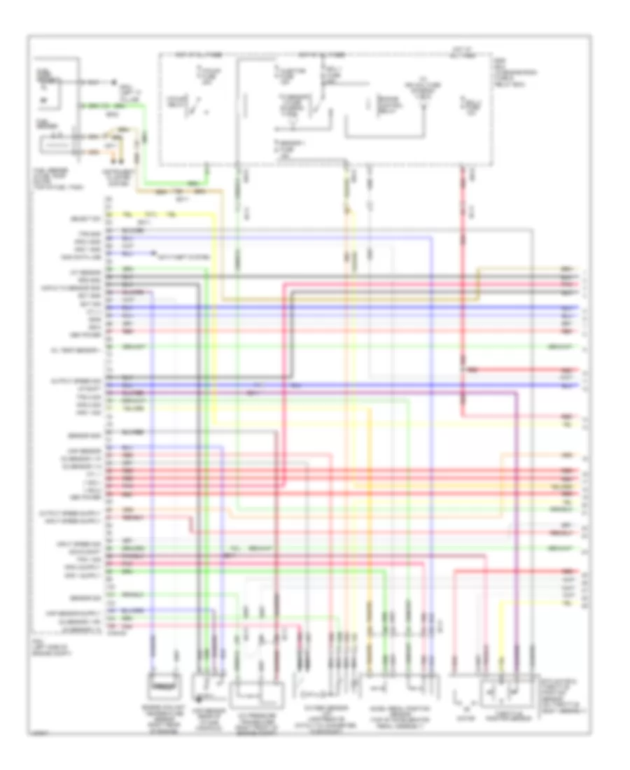
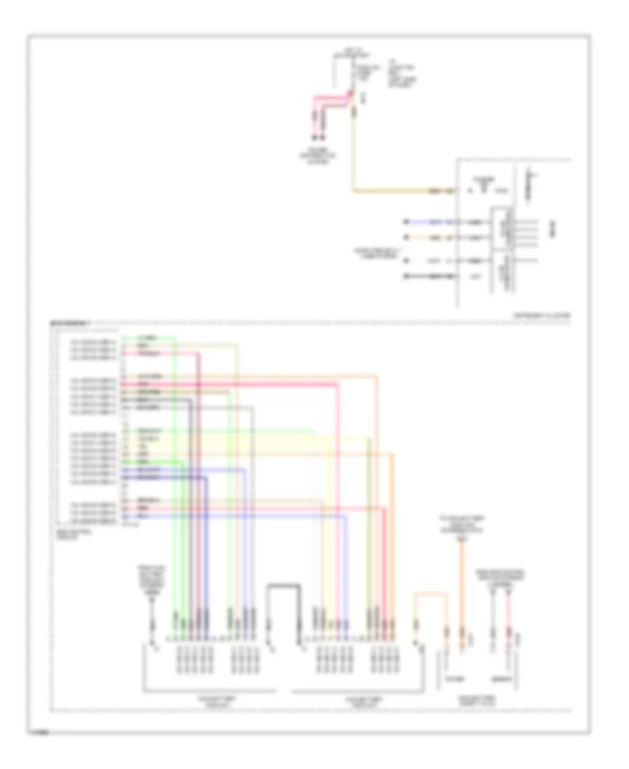
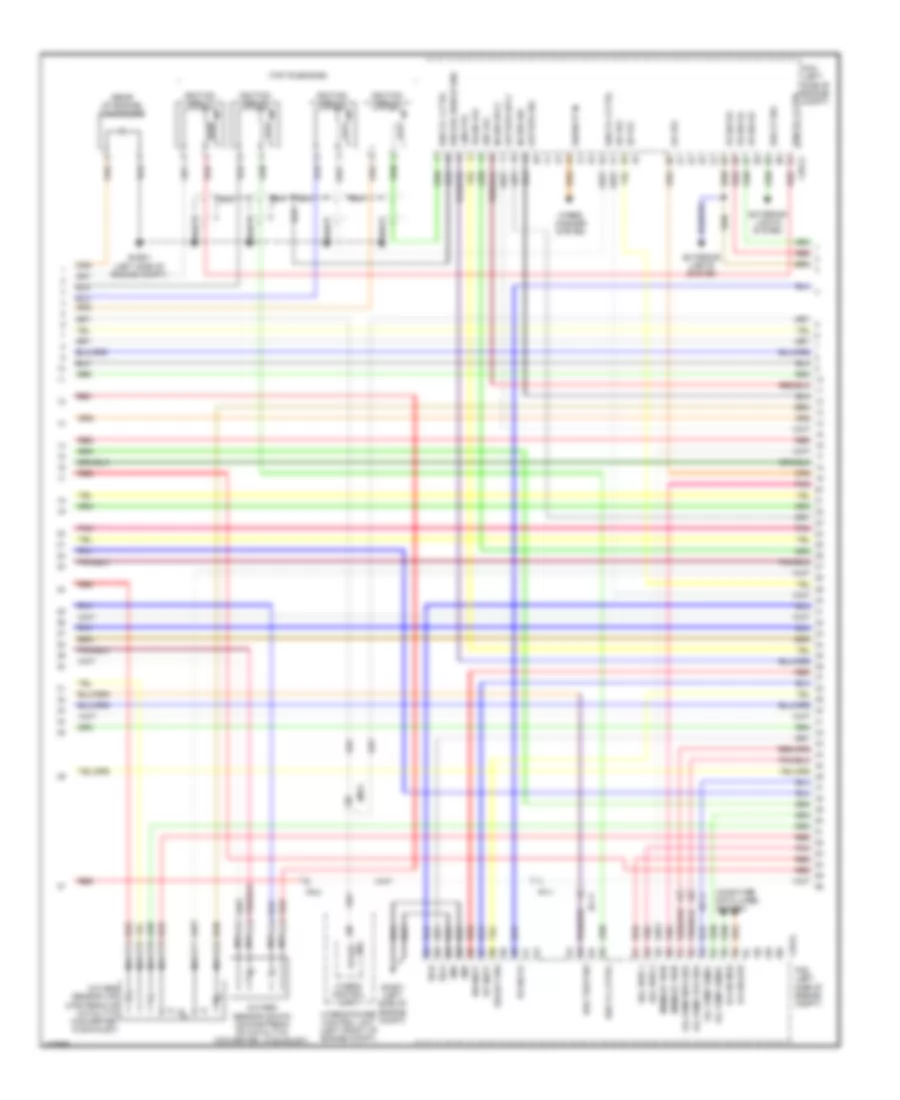
2.0L Turbo, Engine Performance Wiring Diagram (1 of 5) for Hyundai Sonata Limited 2014
 https://portal-diagnostov.com/license.html
Automotive Electricians Portal FZCO
Automotive Electricians Portal FZCO
https://portal-diagnostov.com/license.html
https://portal-diagnostov.com/license.html
Automotive Electricians Portal FZCO
Automotive Electricians Portal FZCO
List of elements for 2.0L Turbo, Engine Performance Wiring Diagram (1 of 5) for Hyundai Sonata Limited 2014:
- (diagram 4 of 5)
- 2 fuse
- A/c pressure transducer (right front of engine compt)
- Accel pedal position sensor (top of accelerator pedal assembly)
- Anti-theft system
- Aps 1 gnd
- Aps 1 sig
- Aps 2 gnd
- Aps 2 sig
- Body assembly)
- Chtg-ag
- Cyl 1
- Cyl 3
- Down shift
- E/r-a
- E/r-b
- Ec11
- Ect gnd
- Ect sig
- Ecu 1 fuse 30a
- Ecu 3 fuse 10a
- Ef02
- Electric waste gate actuator (center rear of engine compt)
- Ems box (in engine room fuse & relay box)
- Engine control relay
- Engine coolant temperature sensor (right rear of engine)
- Etc motor & throttle position sensor (on throttle
- F/pump fuse 20a
- F/pump relay
- Fuel pump motor
- Fuel sender
- Fuel sender & fuel pump motor (top of fuel tank)
- Gf04 (left "c" pillar)
- Hot at all times
- Iat sensor
- Immo data line
- Injector fuse 15a
- Input speed sig
- Instrument cluster system
- Map & tia sensor gnd
- Map sensor
- Map sensor 1 (middle of intake manifold)
- Map sensor 2 gnd
- Mem power
- Motor
- Nca
- O2 sensor v g
- O2 sensor v ip
- O2 sensor v n
- O2 sensor v rc
- Oil temp sensor (+)
- Ots sig
- Output speed sig
- Oxygen sensor (up) (upstream of catalytic converter, in exhaust)
- Pcm (left side of engine compt)
- Pnk
- Red
- Rps gnd
- Select sw
- Sensor 1 fuse 15a
- Sensor gnd
- Sensor sig
- Ss-a
- Ss-b
- Throttle position sensor
- To ign coil fuse (diagram 4 of 5)
- To sensor
- Tps 1 sig
- Tps 2 sig
- Tps gnd
- Up shift
- V sol1
- V sol2
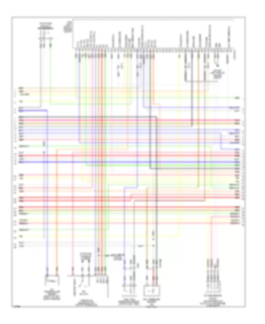
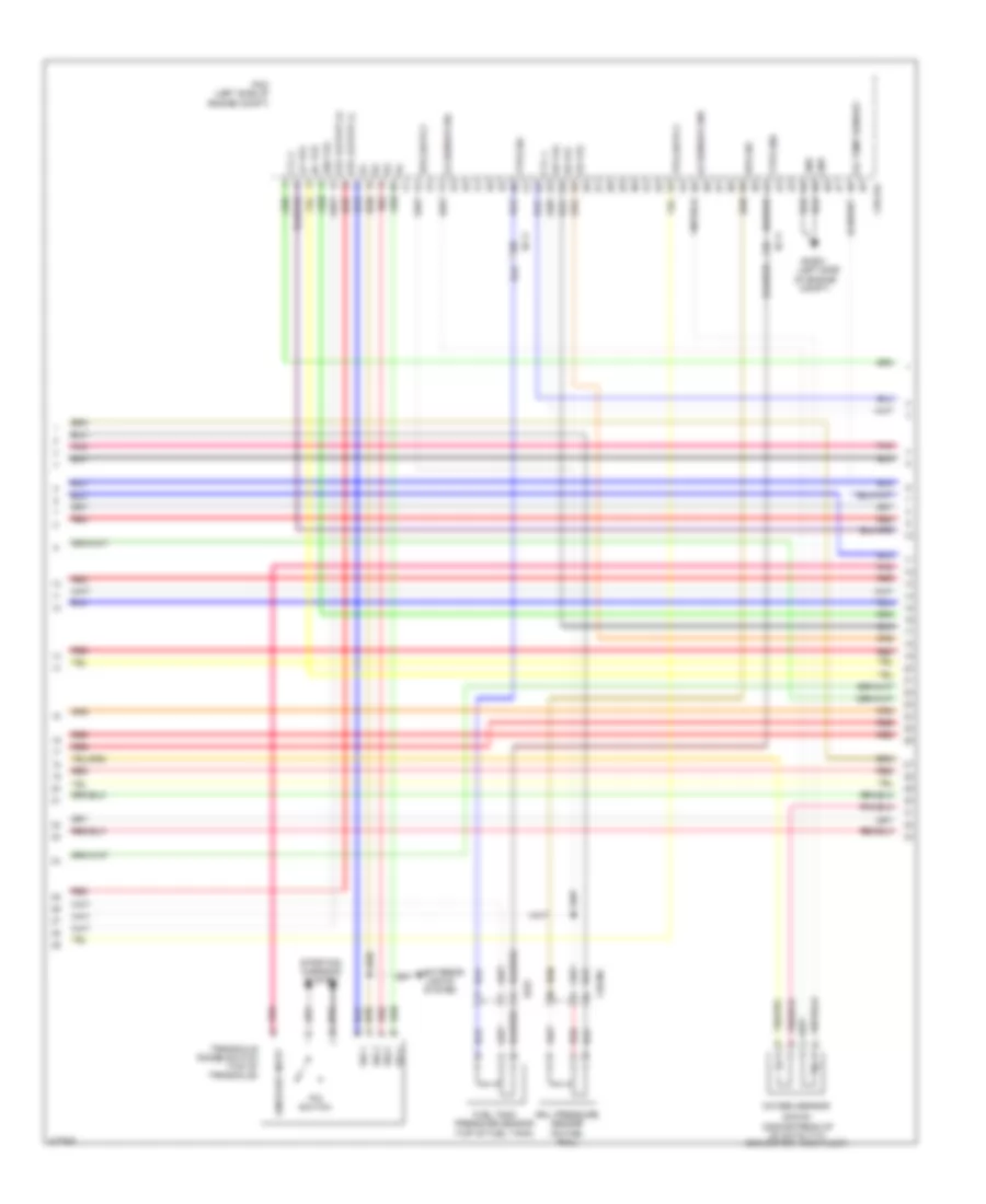
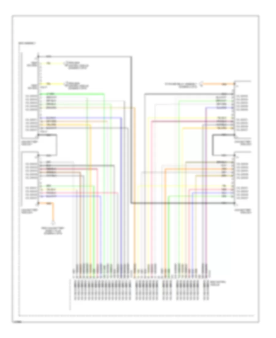
2.0L Turbo, Engine Performance Wiring Diagram (2 of 5) for Hyundai Sonata Limited 2014
List of elements for 2.0L Turbo, Engine Performance Wiring Diagram (2 of 5) for Hyundai Sonata Limited 2014:
- (down)
- (downstream of catalytic converter, in exhaust)
- (on fuel rail)
- (on intake air duct) map sensor 2
- 26 vfs
- 35r vfs
- Chtg-ag
- Chtginj
- Cyl 2
- Cyl 4
- Dc vfs
- Ec11
- Ef01
- Etc output (+)
- Etc output (-)
- Ewga dc mtr out (+)
- Ewga dc mtr out (-)
- Ewga gnd
- Ewga snsr
- Exterior lights system
- Ftps gnd
- Ftps sig
- Fuel tank pressure sensor (top of fuel tank)
- Ghtg01 (left side of engine compt)
- Gnd
- Lp vfs
- Map sensor 2 sig
- Nca
- O2 sensor gnd
- O2 sensor sig
- Od vfs
- Oil temp sensor (-)
- Oil temperature sensor (front of left side of engine)
- On/start input
- Ots gnd
- Oxygen sensor
- P/n switch
- Pcm (left side of engine compt)
- Pnk
- Rail pressure sensor
- Red
- Rps sensor
- Sig 1
- Sig 2
- Sig 3
- Sig 4
- Starting/ charging system
- Transaxle range switch (top of transaxle)
- Ud vfs
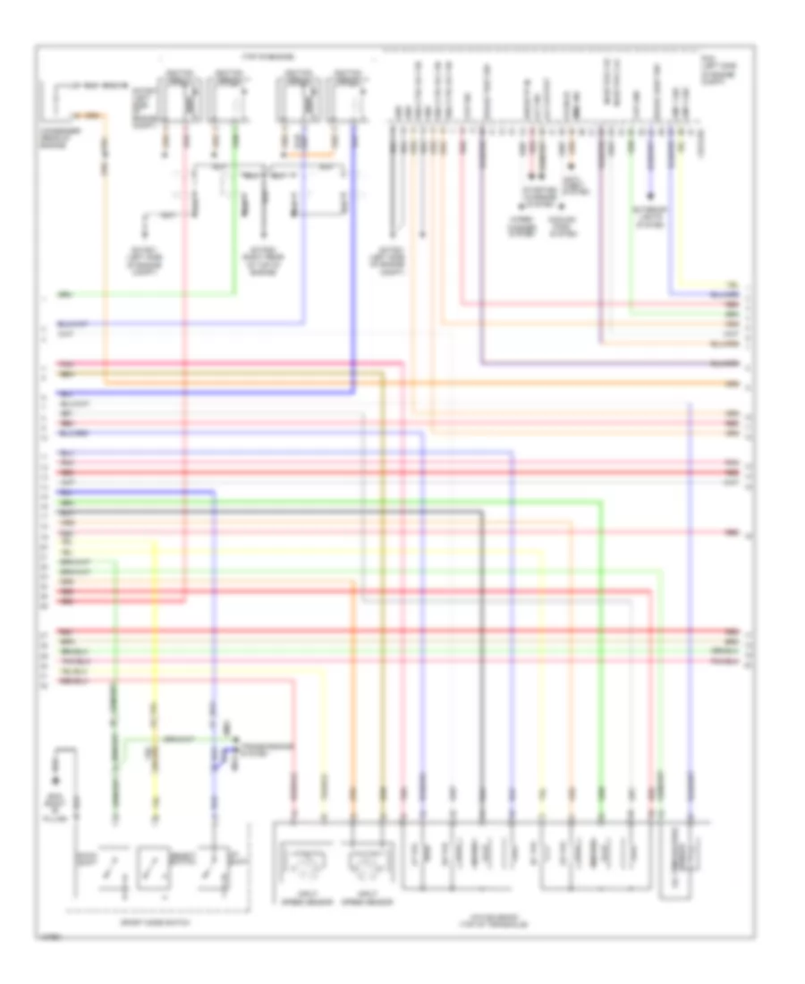
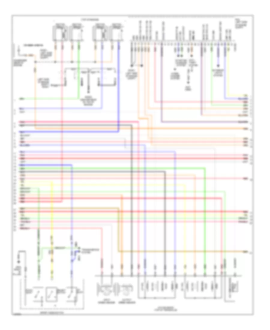
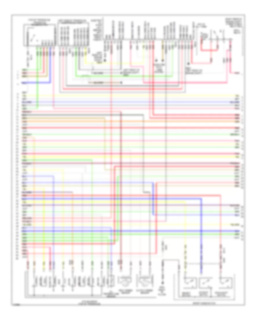
2.0L Turbo, Engine Performance Wiring Diagram (3 of 5) for Hyundai Sonata Limited 2014
List of elements for 2.0L Turbo, Engine Performance Wiring Diagram (3 of 5) for Hyundai Sonata Limited 2014:
- (top of engine)
- 26 vfs
- 35r vfs
- Alt output
- Alt sig
- Anti- theft system
- Atm solenoid (top of transaxle)
- Brake light sw
- Brake test sw
- C/fan hi
- Chtg-bg
- Ckp gnd
- Ckp sig
- Cmp 1 sig
- Cmp 2 sig
- Condenser (rear of engine)
- Cooling
- Dc vfs
- Down shift
- Em61
- Eng ctrl rly on
- Exterior lights
- Fans system
- Gf03 (right "b" pillar)
- Ghtg01 (left side of engine compt)
- Ghtg02 (right rear of top of engine)
- Gnd
- Ignition coil 1
- Ignition coil 2
- Ignition coil 3
- Ignition coil 4
- Immo ind
- Injector 2 hi
- Injector 2 lo
- Input speed sensor
- Lp vfs
- Mf61
- Od vfs
- Of engine compt)
- Pcm (left side
- Pnk
- Red
- Select switch
- Sensor oil temperature
- Sport mode switch
- Starting/ charging system
- System
- Transmissions system
- Ud vfs
- Up shift
- Wiper "p" in
- Wiper/ washer system
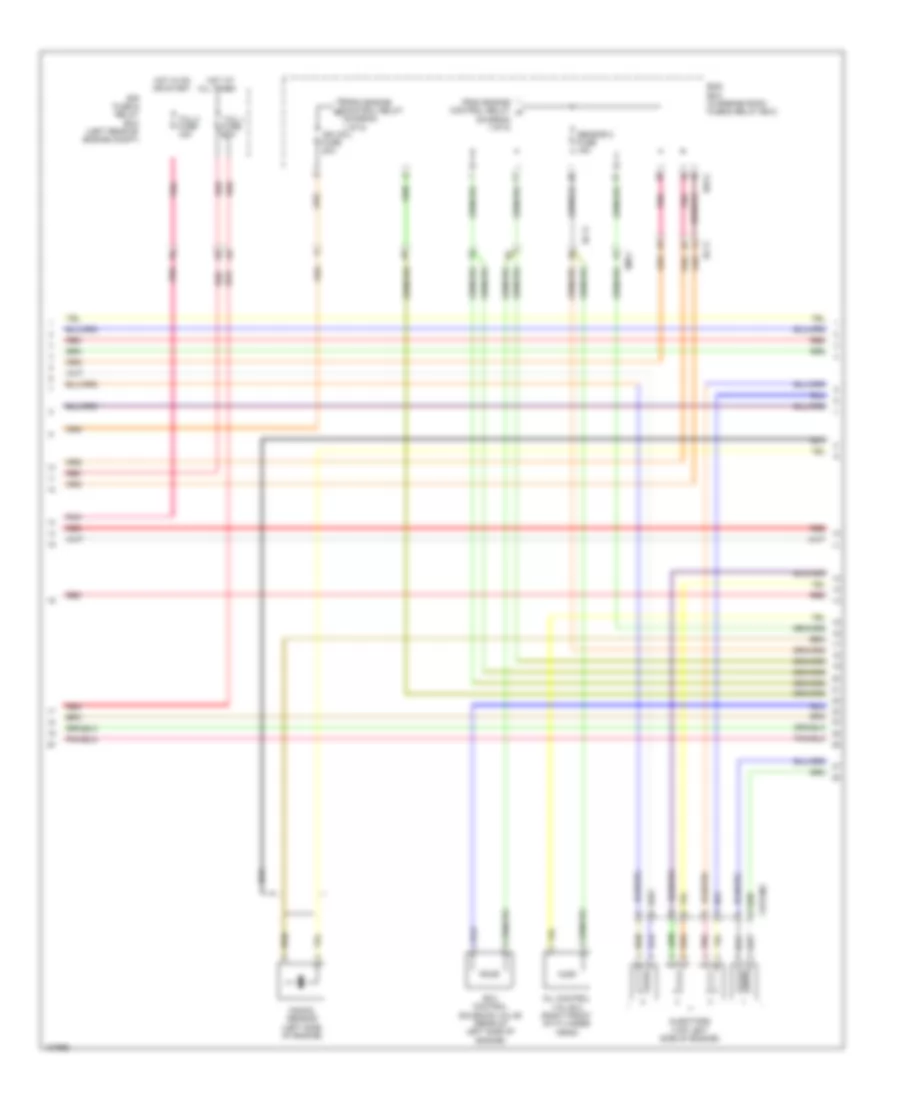
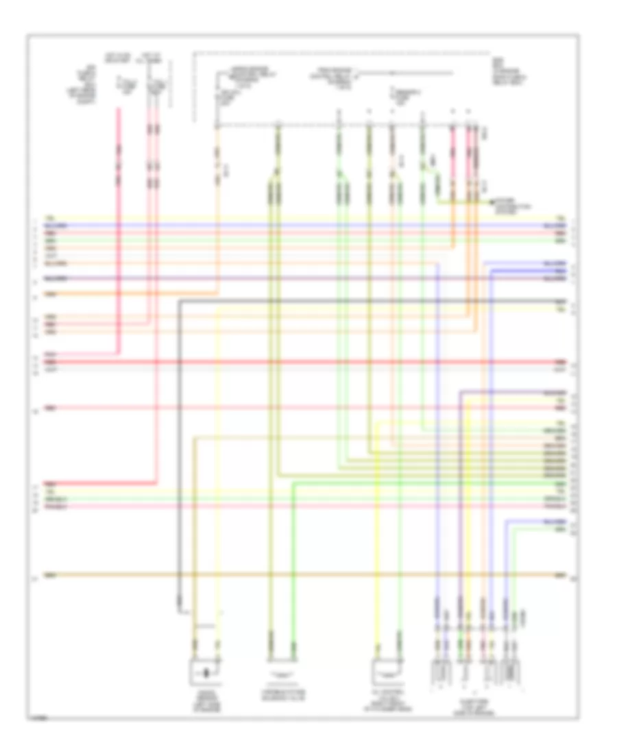
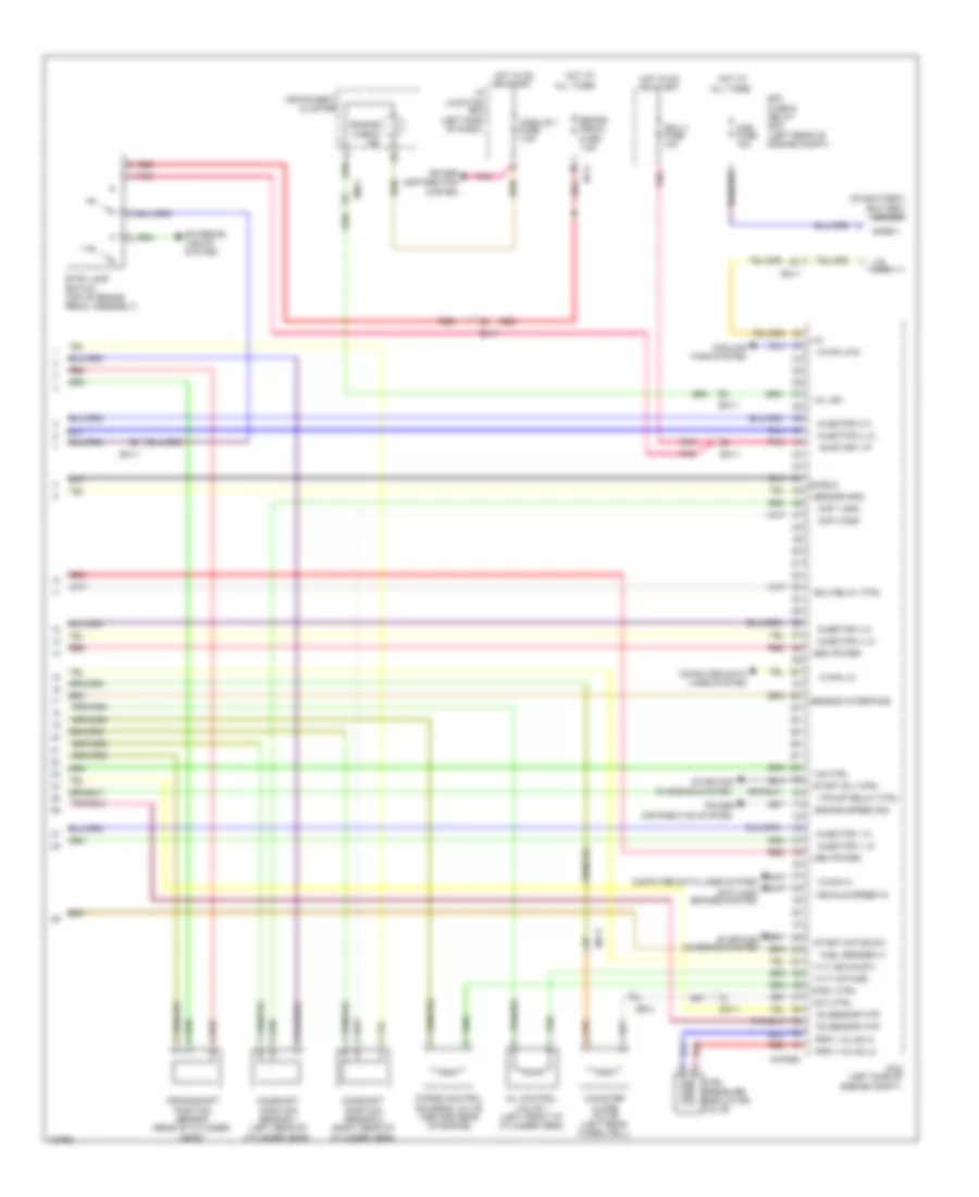
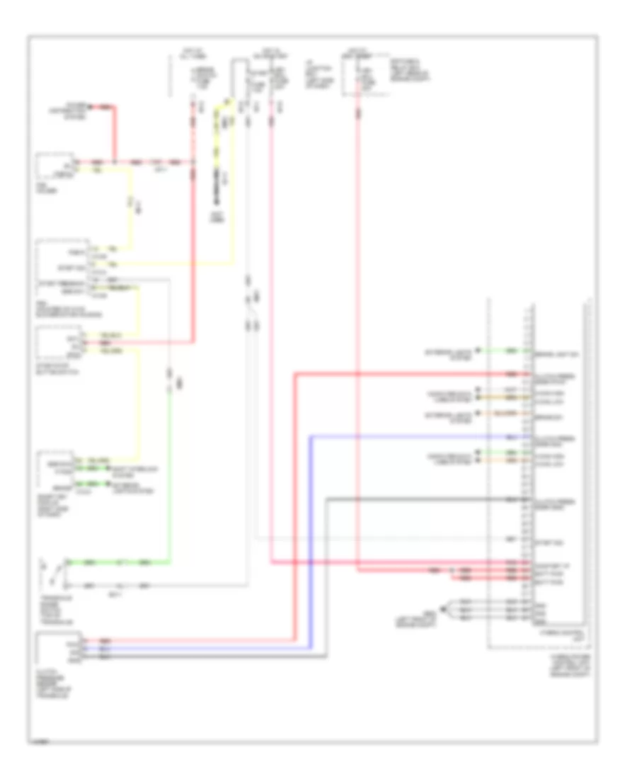
2.0L Turbo, Engine Performance Wiring Diagram (4 of 5) for Hyundai Sonata Limited 2014
List of elements for 2.0L Turbo, Engine Performance Wiring Diagram (4 of 5) for Hyundai Sonata Limited 2014:
- (diagram 1 of 5)
- (top left side of engine)
- All times
- Chtginj
- E/r fuse & relay box (left rear of engine compt)
- E/r-a
- Ec11
- Em11
- Ems box (in engine room fuse & relay box)
- From engine control relay a
- From engine control relay b
- Hot at
- Hot in on or start
- Ign coil fuse 20a
- Injectors
- Knock sensor (left side of engine)
- Oil control valve 2 (right front of cylinder head)
- Pnk
- Rcv control solenoid valve (rear of left side of engine)
- Red
- Sensor 2 fuse 15a
- Tcu 1 fuse 20a
- Tcu 2 fuse 15a
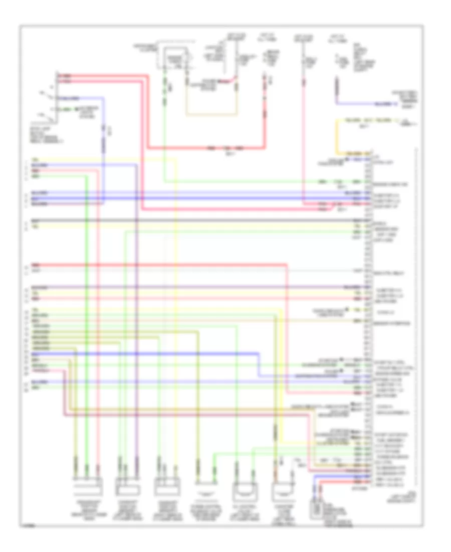
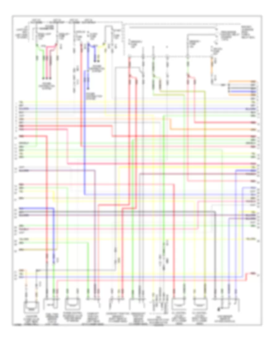
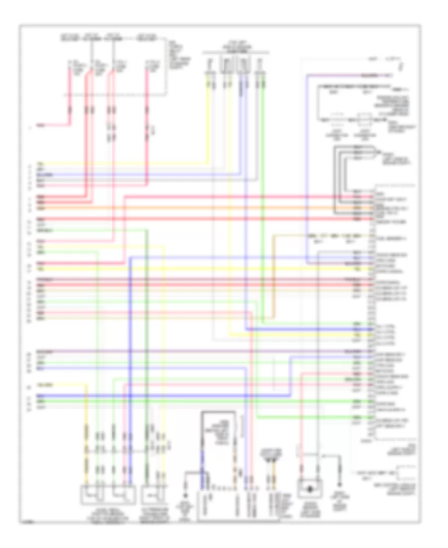
2.0L Turbo, Engine Performance Wiring Diagram (5 of 5) for Hyundai Sonata Limited 2014
List of elements for 2.0L Turbo, Engine Performance Wiring Diagram (5 of 5) for Hyundai Sonata Limited 2014:
- (left side of
- (left side of dash)
- (on battery) battery sensor
- All times
- Ams fuse 15a
- Anti-lock brakes system
- Brake pedal fuse 7.5a
- Bypass valve
- C-can hi
- C-can lo
- C/fan low
- Camshaft position sensor 1 (left rear of cylinder head)
- Camshaft position sensor 2 (right rear of cylinder head)
- Canister close valve (left rear wheelwell)
- Ccv ctrl
- Charging system
- Chtg-bg
- Cluster system
- Cmp 1 gnd
- Cmp 2 gnd
- Computer data
- Computer data lines system
- Cooling
- Crankshaft position sensor (rear of cylinder head)
- Distribution system
- E/r fuse & relay box (left rear of engine compt)
- Ec11
- Ecu 4 fuse 10a
- Ef01
- Em11
- Eng ctrl relay
- Engine check ind
- Engine compt)
- Engine speed sig
- Exterior lights
- F/pump relay ctrl
- Fans system
- Frpv valve hi
- Frpv valve lo
- Fuel pressure regulator valve (right side of top of engine)
- Fuel sender +
- Hot at
- Hot at all times
- Hot in on or start
- I/p junction box
- I/p-g
- Injector 1 hi
- Injector 1 lo
- Injector 3 hi
- Injector 3 lo
- Injector 4 hi
- Injector 4 lo
- Instrument
- Instrument cluster
- Ivvt (exhaust)
- Ivvt (intake)
- Lin
- Lin line
- Lines system
- Mem power
- Mf11
- Module 1 fuse 7.5a
- O2 sensor htr
- Oil control valve 1 (left front of cylinder head)
- On/start i/p
- Pcm
- Pnk
- Power
- Power distribution system
- Purge control solenoid valve (center rear of engine)
- Purge solenoid
- Red
- Sensor gnd
- Sensor interface
- Shield
- Snsr +
- Start motor sw
- Start rly ctrl
- Starting/
- Stop lamp switch (top of brake pedal assembly)
- System
- Vehicle speed in
2.4L
2.4L, Engine Performance Wiring Diagram (1 of 5) for Hyundai Sonata Limited 2014
List of elements for 2.4L, Engine Performance Wiring Diagram (1 of 5) for Hyundai Sonata Limited 2014:
- (diagram 4 of 5)
- 2 fuse
- A/c pressure transducer (right front of engine compt)
- Accel pedal position sensor (top of accelerator pedal assembly)
- Anti-theft system
- Aps 1 gnd
- Aps 1 sig
- Aps 2 gnd
- Aps 2 sig
- Body assembly)
- Chg-ag
- Cyl 1
- Cyl 3
- Down shift
- E/r-a
- E/r-b
- Ec11
- Ect gnd
- Ect sig
- Ecu 1 fuse 30a
- Ecu 3 fuse 10a
- Ef02
- Em11
- Ems box (in engine room fuse & relay box)
- Engine control relay
- Engine coolant temperature sensor (right rear of engine)
- Etc motor & throttle position sensor (on throttle
- F/pump fuse 20a
- F/pump relay
- Fuel pump motor
- Fuel sender
- Fuel sender & fuel pump motor (top of fuel tank)
- Gf04 (left "c"
- Hot at all times
- Iat sensor
- Immo data line
- Injector fuse 15a
- Input speed sig
- Instrument cluster system
- Map & tia sensor gnd
- Map sensor
- Map sensor (rear of intake manifold)
- Mem power
- Mf11
- Motor
- Nca
- O2 sensor v g
- O2 sensor v ip
- O2 sensor v n
- O2 sensor v rc
- Oil temp sensor +
- Output speed sig
- Oxygen sensor (up) (upstream of catalytic converter, in exhaust)
- Pcm (left side of engine compt)
- Pillar)
- Pnk
- Red
- Rps gnd
- Select sw
- Sensor
- Sensor 1 fuse 15a
- Sensor gnd
- Sensor sig
- Ss-a
- Ss-b
- Throttle position sensor
- To ign coil fuse (diagram 4 of 5)
- To sensor
- Tps 1 sig
- Tps 2 sig
- Tps gnd
- Up shift
- V sol1
- V sol2
2.4L, Engine Performance Wiring Diagram (2 of 5) for Hyundai Sonata Limited 2014
List of elements for 2.4L, Engine Performance Wiring Diagram (2 of 5) for Hyundai Sonata Limited 2014:
- (down)
- (downstream of of catalytic converter, in exhaust)
- (left side
- 26 vfs
- 35r vfs
- Chg-ag
- Chginj
- Cyl 2
- Cyl 4
- Dc vfs
- Ec11
- Ef01
- Etc output (+)
- Etc output (-)
- Exterior lights system
- Ftps gnd
- Ftps sig
- Fuel tank pressure sensor (top of fuel tank)
- Ghg01
- Gnd
- Lp vfs
- O2 sensor gnd
- O2 sensor sig
- Od vfs
- Of engine compt)
- Oil temp sensor -
- On/start input
- Oxygen sensor
- P/n switch
- Pcm (left side of engine compt)
- Pnk
- Rail pressure sensor (on fuel rail)
- Red
- Rps sig
- Sig 1
- Sig 2
- Sig 3
- Sig 4
- Starting/ charging system
- Transaxle range switch (top of transaxle)
- Ud vfs
2.4L, Engine Performance Wiring Diagram (3 of 5) for Hyundai Sonata Limited 2014
List of elements for 2.4L, Engine Performance Wiring Diagram (3 of 5) for Hyundai Sonata Limited 2014:
- (left side
- (not used)
- (rear of engine)
- (top of engine)
- 26 vfs
- 35r vfs
- Alt output
- Alt sig
- Anti- theft system
- Atm solenoid (top of transaxle)
- Brake light sw
- Brake test sw
- C/can hi
- Chg-bg
- Ckp gnd
- Ckp sig
- Cmp 1 sig
- Cmp 2 sig
- Condenser
- Dc vfs
- Down shift
- Ec11
- Em61
- Eng ctrl rly on
- Exterior lights
- Gf03 (right "b" pillar)
- Ghg01
- Ghg01 (left side of engine compt)
- Ghg02 (center rear of top of engine)
- Gnd
- Ignition coil 1
- Ignition coil 2
- Ignition coil 3
- Ignition coil 4
- Immo ind
- Injector 2 hi
- Injector 2 lo
- Input speed sensor
- Lp vfs
- Mf61
- Od vfs
- Of engine compt)
- Of engine compt) ghg01
- Oil temperature
- Output speed sensor
- Pcm (left side
- Pnk
- Red
- Select switch
- Sensor
- Sport mode switch
- Ss-a
- Ss-b
- Starting/ charging system
- System
- Transmissions system
- Ud vfs
- Up shift
- Wiper "p" in
- Wiper/ washer system
2.4L, Engine Performance Wiring Diagram (4 of 5) for Hyundai Sonata Limited 2014
List of elements for 2.4L, Engine Performance Wiring Diagram (4 of 5) for Hyundai Sonata Limited 2014:
- (top left side of engine)
- All times
- Chginj
- E/r fuse & relay box (left rear of engine compt)
- E/r-a
- Ec11
- Em11
- Ems box (in engine room fuse & relay box)
- From engine control relay (diagram 1 of 5)
- From engine control relay a (diagram 1 of 5)
- Hot at
- Hot in on or start
- Ign coil fuse 20a
- Injectors
- Knock sensor (left side of engine)
- Oil control valve 2 (right front of cylinder head)
- Pnk
- Power distribution system
- Red
- Sensor 2 fuse 15a
- Tcu 1 fuse 20a
- Tcu 2 fuse 15a
- Variable intake solenoid valve
2.4L, Engine Performance Wiring Diagram (5 of 5) for Hyundai Sonata Limited 2014
List of elements for 2.4L, Engine Performance Wiring Diagram (5 of 5) for Hyundai Sonata Limited 2014:
- (left side
- (left side of
- (on battery) battery sensor
- All times
- Ams fuse 15a
- Anti-lock brakes system
- Brake pedal fuse 7.5a
- C-can hi
- C-can lo
- C/can low
- Camshaft position sensor 1 (left rear of cylinder head)
- Camshaft position sensor 2 (right rear of cylinder head)
- Canister close valve (left rear wheelwell)
- Ccv ctrl
- Charging system
- Chg-bg
- Cmp 1 gnd
- Cmp 2 gnd
- Computer data
- Computer data lines system
- Cooling fans system
- Crankshaft position sensor (rear of cylinder head)
- Distribution system
- E/r fuse & relay box (left rear of engine compt)
- Ec11
- Ecu 4 fuse 10a
- Ecu relay ctrl
- Ef01
- Em11
- Engine check ind
- Engine compt)
- Engine speed sig
- Exterior lights system
- F/pump relay ctrl
- Frpv valve hi
- Frpv valve lo
- Fuel
- Fuel sender (+)
- Hot at
- Hot in on or start
- I/p junction box
- I/p-g
- Injector 1 hi
- Injector 1 lo
- Injector 3 hi
- Injector 3 lo
- Injector 4 hi
- Injector 4 lo
- Instrument cluster
- Ivvt (exhaust)
- Ivvt (intake)
- Lin
- Lin line
- Lines system
- Mem power
- Mf11
- Mil ind
- Module 1 fuse 7.5a
- O2 sensor htr
- Of dash)
- Oil control valve 1 (left front of cylinder head)
- On/start i/p
- Pcm
- Pcsv ctrl
- Pnk
- Power
- Power distribution system
- Pressure regulator
- Purge control solenoid valve (center rear of engine)
- Red
- Sensor gnd
- Sensor interface
- Shield
- Snsr +
- Start motor sw
- Start rly ctrl
- Starting/
- Stop lamp switch (top of brake pedal assembly)
- Valve
- Vehicle speed in
- Vis ctrl
2.4L HYBRID
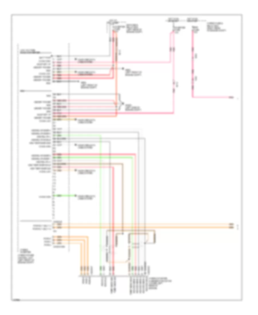
2.4L Hybrid, Hybrid Control Wiring Diagram (1 of 6) for Hyundai Sonata Limited 2014
List of elements for 2.4L Hybrid, Hybrid Control Wiring Diagram (1 of 6) for Hyundai Sonata Limited 2014:
- Batt pwr
- Bms fuse 10a
- C-can high
- C-can low
- Chg33-p
- Chg33-s
- Chg34-hsg
- Chg34-s
- Computer data lines system
- E/r fuse & relay box (left rear of engine compt)
- Ec11
- Ef01
- F81
- Ff01
- Ge02 (left front of engine compt)
- Ge08 (left front of engine compt)
- Ghg01 (left side of engine compt)
- Gnd
- H-can high
- H-can low
- Hot at all times
- Hot in on or start
- Hsg rslvr (+)
- Hsg rslvr (-)
- Hsg rslvr shield
- Hsg rslvr snsr 1
- Hsg rslvr snsr 2
- Hsg rslvr snsr 3
- Hsg rslvr snsr 4
- Hsg temp snsr gnd
- Hsg temp snsr shld
- Hsg temp snsr sig
- Hybrid fuse & relay box (right rear of engine compt)
- Hybrid inverter
- Hybrid power control unit (left front of engine compt)
- Hybrid starter & generator motor (lower left rear of engine)
- Inverter fuse 10a
- Low voltage dc-dc converter
- Mcu
- Memory power
- On/start i/p
- Pnk
- Pwr rly asly (+)
- Pwr rly asly (-)
- Pwr-u
- Pwr-v
- Pwr-w
- Red
- Rslver shld
- Rslver snsr 1
- Rslver snsr 2
- Rslver snsr 3
- Rslver snsr 4
- Rslvr (+)
- Rslvr (-)
- Temp snsr gnd
- Temp snsr shld
- Temp snsr sig
2.4L Hybrid, Hybrid Control Wiring Diagram (2 of 6) for Hyundai Sonata Limited 2014
List of elements for 2.4L Hybrid, Hybrid Control Wiring Diagram (2 of 6) for Hyundai Sonata Limited 2014:
- (+)
- (-)
- B+ gnd
- Batt pwr
- Battery ambient temperature sensor (on battery)
- Blower f/b
- Blwr f/b
- Bms assembly
- Bms blower motor relay
- Bms c/fan fuse 15a
- Bms control module
- Bms fuse 10a
- C-can high
- C-can low
- Computer data lines system
- Control
- Crash input
- E/r fuse & relay box (left rear of engine compt)
- Em11
- F71
- Fan spd
- Ff01
- Ff02
- From main battery module 9 (diagram 5 of 6)
- Gf02 (left "b" pillar)
- Gf04 (left "c" pillar)
- Gnd
- Gnd bms blower motor
- H-can high
- H-can low
- Hot at all times
- I/p junction box (left side of dash)
- I/p-g
- Main battery
- Main rly
- Main rly (+)
- Main rly (-)
- Main+ rly
- Mf11
- On/start i/p
- P5v
- Pnk
- Power relay assembly
- Prchrg rly
- Pre rly
- Pwm in
- Red
- Rly gnd
- Sig
- To main battery safety plug (diagram 4 of 6)
- Vib 5v
- Vib gnd
- Vout
2.4L Hybrid, Hybrid Control Wiring Diagram (3 of 6) for Hyundai Sonata Limited 2014
List of elements for 2.4L Hybrid, Hybrid Control Wiring Diagram (3 of 6) for Hyundai Sonata Limited 2014:
- (+)
- (-)
- Bms assembly
- Bms control module
- F71-t
- F71-v1
- F75-t1
- F75-v1
- Gnd
- Main battery module 1
- Main battery module 2
- Main battery module 3
- Main battery thermistor
- Nca
- Pnk
- Red
- Sig
- Temp sig (gnd 1)
- Temp sig (gnd 7)
- Temp sig (gnd)
- Temp sig (mbm 1)
- Temp sig (mbm 7)
- Temp sig (sig)
- Thermistor gnd
- Thermistor sig
- To main battery module 4 (diagram 4 of 6)
- To main battery module 7 (diagram 5 of 6)
- Vol sig c0
- Vol sig c1
- Vol sig c2
- Vol sig c3
- Vol sig c4
- Vol sig c5
- Vol sig c6
- Vol sig c7
- Vol sig c8
- Vol sig-c0 (mbm 1)
- Vol sig-c0 (mbm 2)
- Vol sig-c0 (mbm 3)
- Vol sig-c1 (mbm 1)
- Vol sig-c1 (mbm 2)
- Vol sig-c1 (mbm 3)
- Vol sig-c2 (mbm 1)
- Vol sig-c2 (mbm 2)
- Vol sig-c2 (mbm 3)
- Vol sig-c3 (mbm 1)
- Vol sig-c3 (mbm 2)
- Vol sig-c3 (mbm 3)
- Vol sig-c4 (mbm 1)
- Vol sig-c4 (mbm 2)
- Vol sig-c4 (mbm 3)
- Vol sig-c5 (mbm 1)
- Vol sig-c5 (mbm 2)
- Vol sig-c5 (mbm 3)
- Vol sig-c6 (mbm 1)
- Vol sig-c6 (mbm 2)
- Vol sig-c6 (mbm 3)
- Vol sig-c7 (mbm 1)
- Vol sig-c7 (mbm 2)
- Vol sig-c7 (mbm 3)
- Vol sig-c8 (mbm 1)
- Vol sig-c8 (mbm 2)
- Vol sig-c8 (mbm 3)
2.4L Hybrid, Hybrid Control Wiring Diagram (4 of 6) for Hyundai Sonata Limited 2014
List of elements for 2.4L Hybrid, Hybrid Control Wiring Diagram (4 of 6) for Hyundai Sonata Limited 2014:
- (+)
- (-)
- B-can transceiver
- Bms assembly
- Bms control module
- C-can transceiver
- Charge ind
- Computer data lines system
- F71-v2
- F73-p
- F73-s
- From bms control module (diagram 2 of 6)
- From main battery module 3 (diagram 3 of 6)
- High
- Hot in on or start
- I/p junction box (left side of dash)
- I/p-g
- Instrument cluster
- Interface
- Low
- Main battery module 4
- Main battery module 5
- Main battery safety plug
- Micom
- Module 1 fuse 7.5a
- Nca
- Pnk
- Power
- Power distribution system
- Red
- Sensor
- To main battery module 6 (diagram 5 of 6)
- Vol sig c0
- Vol sig c1
- Vol sig c2
- Vol sig c3
- Vol sig c4
- Vol sig c5
- Vol sig c6
- Vol sig c7
- Vol sig c8
- Vol sig-c0 (mbm 4)
- Vol sig-c0 (mbm 5)
- Vol sig-c1 (mbm 4)
- Vol sig-c1 (mbm 5)
- Vol sig-c2 (mbm 4)
- Vol sig-c2 (mbm 5)
- Vol sig-c3 (mbm 4)
- Vol sig-c3 (mbm 5)
- Vol sig-c4 (mbm 4)
- Vol sig-c4 (mbm 5)
- Vol sig-c5 (mbm 4)
- Vol sig-c5 (mbm 5)
- Vol sig-c6 (mbm 4)
- Vol sig-c6 (mbm 5)
- Vol sig-c7 (mbm 4)
- Vol sig-c7 (mbm 5)
- Vol sig-c8 (mbm 4)
- Vol sig-c8 (mbm 5)
2.4L Hybrid, Hybrid Control Wiring Diagram (5 of 6) for Hyundai Sonata Limited 2014
List of elements for 2.4L Hybrid, Hybrid Control Wiring Diagram (5 of 6) for Hyundai Sonata Limited 2014:
- (+)
- (-)
- Bms assembly
- Bms control module
- F71-v3
- F71-v4
- F75-t7
- F75-v7
- From bms control module (diagram 3 of 6)
- From main battery safety plug (diagram 4 of 6)
- Main battery module 6
- Main battery module 7
- Main battery module 8
- Main battery module 9
- Nca
- Red
- Temp sig (gnd)
- Temp sig (sig)
- To power relay assembly (diagram 2 of 6)
- Vol sig-c0
- Vol sig-c0 (mbm 6)
- Vol sig-c0 (mbm 7)
- Vol sig-c0 (mbm 8)
- Vol sig-c0 (mbm 9)
- Vol sig-c1
- Vol sig-c1 (mbm 6)
- Vol sig-c1 (mbm 7)
- Vol sig-c1 (mbm 8)
- Vol sig-c1 (mbm 9)
- Vol sig-c2
- Vol sig-c2 (mbm 6)
- Vol sig-c2 (mbm 7)
- Vol sig-c2 (mbm 8)
- Vol sig-c2 (mbm 9)
- Vol sig-c3
- Vol sig-c3 (mbm 6)
- Vol sig-c3 (mbm 7)
- Vol sig-c3 (mbm 8)
- Vol sig-c3 (mbm 9)
- Vol sig-c4
- Vol sig-c4 (mbm 6)
- Vol sig-c4 (mbm 7)
- Vol sig-c4 (mbm 8)
- Vol sig-c4 (mbm 9)
- Vol sig-c5
- Vol sig-c5 (mbm 6)
- Vol sig-c5 (mbm 7)
- Vol sig-c5 (mbm 8)
- Vol sig-c5 (mbm 9)
- Vol sig-c6
- Vol sig-c6 (mbm 6)
- Vol sig-c6 (mbm 7)
- Vol sig-c6 (mbm 8)
- Vol sig-c6 (mbm 9)
- Vol sig-c7
- Vol sig-c7 (mbm 6)
- Vol sig-c7 (mbm 7)
- Vol sig-c7 (mbm 8)
- Vol sig-c7 (mbm 9)
- Vol sig-c8
- Vol sig-c8 (mbm 6)
- Vol sig-c8 (mbm 7)
- Vol sig-c8 (mbm 8)
- Vol sig-c8 (mbm 9)
2.4L Hybrid, Hybrid Control Wiring Diagram (6 of 6) for Hyundai Sonata Limited 2014
List of elements for 2.4L Hybrid, Hybrid Control Wiring Diagram (6 of 6) for Hyundai Sonata Limited 2014:
- (not used)
- Batt pwr
- Brake
- Brake light sw
- Brake sw
- Brake switch fuse 7.5a
- C-can high
- C-can low
- Clutch press snsr (gnd)
- Clutch press snsr (pwm)
- Clutch press snsr (sig)
- Clutch pressure sensor (left side of transaxle)
- Computer data lines system
- E/r fuse & relay box (left rear of engine compt)
- Ec11
- Em11
- Em31
- Em61
- Exterior lights system
- Fob holder
- Fob-in
- Ge08 (left front of engine compt)
- Gnd
- H-can high
- H-can low
- Hev ecu fuse 20a
- Hot at all times
- Hot in on or start
- Hybrid control unit
- Hybrid power control unit (left front of engine compt)
- I/p junction box (left side of dash)
- I/p-b
- I/p-e
- I/p-f
- I/p-g
- M12-a
- M13-a
- M13-b
- Mf11
- Nca
- On/start i/p
- P pos
- Pdm (mounted of hvac blower motor housing)
- Pnk
- Power distribution system
- Pwm
- Red
- Shift interlock system
- Sig
- Smart key module (right side of dash)
- Ssb sw1
- Ssb sw2
- Start feedback
- Start fuse 7.5a
- Start sig
- Start stop button switch
- Sw1
- Sw2
- Transaxle range switch (top of transaxle)
2.4L Hybrid, MFI Control Wiring Diagram (1 of 5) for Hyundai Sonata Limited 2014
List of elements for 2.4L Hybrid, MFI Control Wiring Diagram (1 of 5) for Hyundai Sonata Limited 2014:
- (top of fuel tank) fuel sender & fuel pump motor
- Anti-theft system
- Aps 1 gnd
- Aps 1 sig
- Apt sensor gnd
- Apt sensor sig
- C-can high
- C-can low
- Ccv ctrl
- Chg-k
- Cmps 1 gnd
- Cmps 1 signal
- Computer data lines system
- Cooling fan rly ctrl(low)
- Cooling fans system
- Cvvt actuator ctrl sig 1
- Cvvt actuator ctrl sig 2
- Data i/o
- E/r fuse & relay box (left rear of engine compt)
- E/r-a
- E/r-b
- Ec11
- Ecu 1 fuse 30a
- Ecu 2 fuse 20a
- Ecu 4 fuse 10a
- Ef01
- Ef02
- Em11
- Ems box (in engine room fuse & relay box)
- Engine control relay
- Engine ctrl rly 'on' in
- Engine ctrl rly ctrl
- Engine speed sig
- Esc 3 fuse 10a
- Etc dc motor 1
- Etc dc motor 2
- Etc motor & throttle position sensor (on throttle body assembly)
- F/pump fuse 20a
- F/pump relay
- Ff11
- Ff21
- Fuel pump motor
- Fuel pump relay ctrl
- Fuel sender
- Gf02 (left "b" pillar)
- Gf04 (left "c" pillar)
- Gnd
- Hot at all times
- Hot in on or start
- Iat sensor
- Immo data line
- Immo ind
- Ind engine check
- Injector fuse 15a
- Instrument cluster
- Map & tia sens gnd
- Mf11
- Micom
- Mil ind
- Motor
- Natural vacuum leak detection (left rear wheelwell)
- Nvld data line
- O2 sens (down) gnd
- O2 sens (down) heater
- O2 sens (down) sig
- O2 sens (up) heater
- Pcm (left side of engine compt)
- Pcsv ctrl
- Pnk
- Pwr
- Red
- Sen sig
- Senr gnd
- Stop lamp switch (top of brake pedal assembly)
- System lights exterior
- System theft anti-
- Throttle position sensor
- To ign coil fuse (diagram 2 of 5)
- To sensor 2 fuse (diagram 2 of 5)
- To snsor 1 fuse (diagram 2 of 5)
- Tps 1 sig
- Tps gnd
2.4L Hybrid, MFI Control Wiring Diagram (2 of 5) for Hyundai Sonata Limited 2014
List of elements for 2.4L Hybrid, MFI Control Wiring Diagram (2 of 5) for Hyundai Sonata Limited 2014:
- Camshaft position sensor 1 (left rear of cylinder head)
- Camshaft position sensor 2 (right rear of cylinder head)
- Canister close valve (left rear wheelwell)
- Clock fuse 10a
- Crankshaft position sensor (rear of cylinder head)
- E/r-a
- Ec11
- Ef01
- Em11
- Em61
- Ems box (in engine room fuse & relay box)
- Ff11
- Ff21
- From engine control relay (diagram 1 of 5)
- Fuel tank pressure sensor (top of fuel tank)
- F_rpm
- Hot at all times
- Hot in acc or run
- Hot in on or start
- I/p junction box (left side of dash)
- I/p-e
- I/p-f
- I/p-g
- Ign coil fuse 20a
- M13-a sig start
- M13-b
- Map sensor (rear of intake manifold)
- Mf11
- Module 1 fuse 7.5a
- Module fuse 7.5a
- Oil control valve 1 (left front of cylinder head)
- Oil control valve 2 (right front of cylinder head)
- Pdm (mounted of hvac blower motor housing)
- Pnk
- Power connector
- Power distribution system
- Purge control solenoid valve (center rear of engine)
- Red
- Reverse
- Room lamp fuse 10a
- Sensor 1 fuse 15a
- Sensor 2 fuse 15a
- Start fuse 7.5a
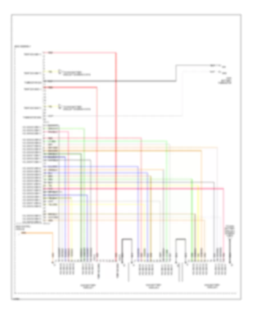
2.4L Hybrid, MFI Control Wiring Diagram (3 of 5) for Hyundai Sonata Limited 2014
List of elements for 2.4L Hybrid, MFI Control Wiring Diagram (3 of 5) for Hyundai Sonata Limited 2014:
- (rear of engine) condenser
- (top of engine)
- 26 vfs
- 35r vfs
- Brk lt sw
- Brk test sw
- Chg-a
- Computer data lines system
- Dn shift
- Ec11
- Em11
- Exterior lights system
- Ff11
- Ff21
- Ghg01 (left side of engine compt)
- Gnd
- H-can high
- H-can low
- Hybrid control unit
- Hybrid power control unit (left front of engine compt)
- Ign coil shield gnd
- Ign cyl 1 ctrl
- Ign cyl 2 ctrl
- Ign cyl 3 ctrl
- Ign cyl 4 ctrl
- Ignition coil 1
- Ignition coil 2
- Ignition coil 3
- Ignition coil 4
- In spd sig
- In spd sply
- Line vfs
- Memory pwr
- Nca
- Od vfs
- Oil pump mtr spd
- Oil pump opu spd
- Oil temp sens+
- Oil temp sens-
- Out spd sig
- Out spd sply
- Oxygen sensor (down) (downstream of catalytic converter, in exhaust)
- Oxygen sensor (up) (upstream of catalytic converter, in exhaust)
- Pcm (left side of engine compt)
- Pnk
- Ps sw s1
- Ps sw s2
- Ps sw s3
- Ps sw s4
- Red
- Select sw
- Sig
- Sol pwr 1
- Sol pwr 2
- Ss-a
- Ss-b
- Start
- T/con vfs
- Ud vfs
- Up shift
- Wiper 'p' in
- Wiper/ washer system
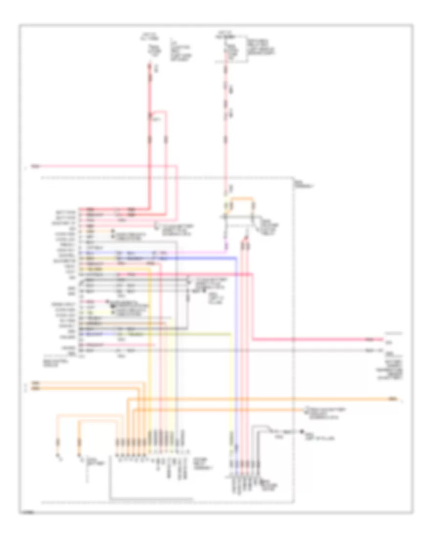
2.4L Hybrid, MFI Control Wiring Diagram (4 of 5) for Hyundai Sonata Limited 2014
List of elements for 2.4L Hybrid, MFI Control Wiring Diagram (4 of 5) for Hyundai Sonata Limited 2014:
- (left front of engine compt)
- (left side of transaxle) electric oil pump
- (right rear of engine compt) hybrid fuse & relay box
- (top of transaxle) transaxle range switch
- 26 vfs
- 35r vfs
- Atm solenoid (top of transaxle)
- Batt pwr
- C-can (high)
- C-can (low)
- Command mtr sp
- Computer data lines system
- Down shift switch
- E62-a
- E62-b
- E64-a
- E64-b
- Ec11
- Ef01
- Electric oil pump unit (behind left side of front fascia)
- Ge07 (left front of engine compt)
- Ge08
- Gf03 (right "b" pillar)
- Gnd
- Hall sens sig-a
- Hall sens sig-b
- Hall sens sig-c
- Hall sens-gnd
- Hall sens-pwr
- Hot at all times
- Input speed sensor
- Line vfs
- Od vfs
- Oil pump unit (u)
- Oil pump unit (v)
- Oil pump unit (w)
- Oil temperature sensor
- On/start input
- Opcu fuse 80a red
- Opcu relay
- Opcu rly ctrl
- Opcu rly input
- Opu status
- Output speed sensor
- P/n switch
- Pnk
- Pump pwr-u
- Pump pwr-v
- Pump pwr-w
- Red
- Select switch
- Sig 1
- Sig 2
- Sig 3
- Sig 4
- Sport mode switch
- Ss-a
- Ss-b
- T/con vfs
- Ud vfs
- Up shift switch
2.4L Hybrid, MFI Control Wiring Diagram (5 of 5) for Hyundai Sonata Limited 2014
List of elements for 2.4L Hybrid, MFI Control Wiring Diagram (5 of 5) for Hyundai Sonata Limited 2014:
- (top left side of engine) injectors
- A/c pressure transducer (right front of engine compt)
- Acc/on input
- Accel pedal position sensor (top of accelerator pedal assembly)
- Aps 2 gnd
- Aps 2 sig
- Apt sens sply
- C-can (high)
- C-can (low)
- Chg-k
- Ckps gnd
- Ckps signal
- Cmps 2 gnd
- Cmps 2 signal
- Computer data lines system
- E/r fuse & relay box (left rear of engine compt)
- Ec11
- Ects gnd
- Ects sig
- Em11
- Em61
- Engine coolant temperature sensor & sender (rear of cylinder head)
- Esc control module (left rear of engine compt)
- Fuel sender (+)
- Ghg01 (left side of engine compt)
- Gm03 (top left side of dash)
- Gm04 (center right of dash)
- Gnd
- Gnd engine ctrl rly ctrl 'on' in gnd
- Hot at all times
- Hot in on or start
- Inj 1 ctrl
- Inj 2 ctrl
- Inj 3 ctrl
- Inj 4 ctrl
- Joint connector umc
- Joint connector umd
- Knock sens gnd
- Knock sens sig
- Knock sensor (left side of engine)
- Map sens sig
- Map sens sply
- Memory power
- Memory pwr
- Nca
- O2 sens (up) vg
- O2 sens (up) vip
- O2 sens (up) vn
- O2 sens (up) vrc
- Oil pump 1 fuse 20a
- Oil pump 2 fuse 10a
- On/start input
- Pcm (left side of engine compt)
- Pnk
- Red
- Tcu 1 fuse 20a
- Tcu 2 fuse 15a
- Tps 2 sig
- Vehicle spd in
- Vess speaker (behind left side of front fascia)
- Vess spek +
- Vess spek -
- Vess unit (right end of dash)
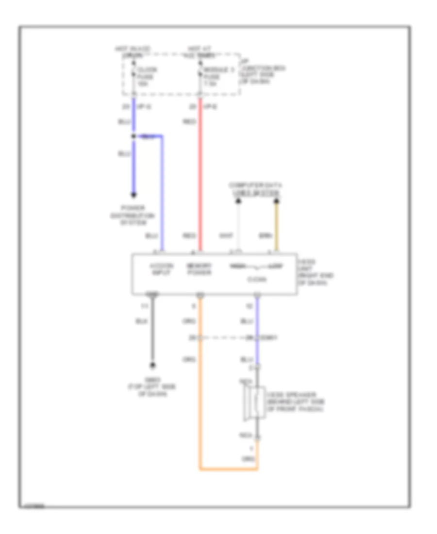
2.4L Hybrid, Virtual Engine Sound System Wiring Diagram for Hyundai Sonata Limited 2014
List of elements for 2.4L Hybrid, Virtual Engine Sound System Wiring Diagram for Hyundai Sonata Limited 2014:
- (+)
- (-)
- Acc/on input
- C-can
- Clock fuse 10a
- Computer data lines system
- Em61
- Gm03 (top left side of dash)
- Gnd
- High
- Hot at all times
- Hot in acc or on
- I/p junction box (left side of dash)
- I/p-e
- I/p-g
- Low
- Memory power
- Module 3 fuse 7.5a
- Nca
- Power distribution system
- Red
- Vess speaker (behind left side of front fascia)
- Vess unit (right end of dash)

 Čeština
 Dansk
Dansk Deutsch
 Ελληνικά
 English
 Español
 Suomi
Suomi Français
 Français
 עברית
עברית Hrvatski
 Magyar
 Italiano
 日本語
日本語 한국어
한국어 Nederlands
 Polski
 Português
 Português
 Română
 Русский
 Slovenčina
 Slovenščina
 Svenska
 Türkçe
 中文 (中国)