ENGINE PERFORMANCE
3.5L
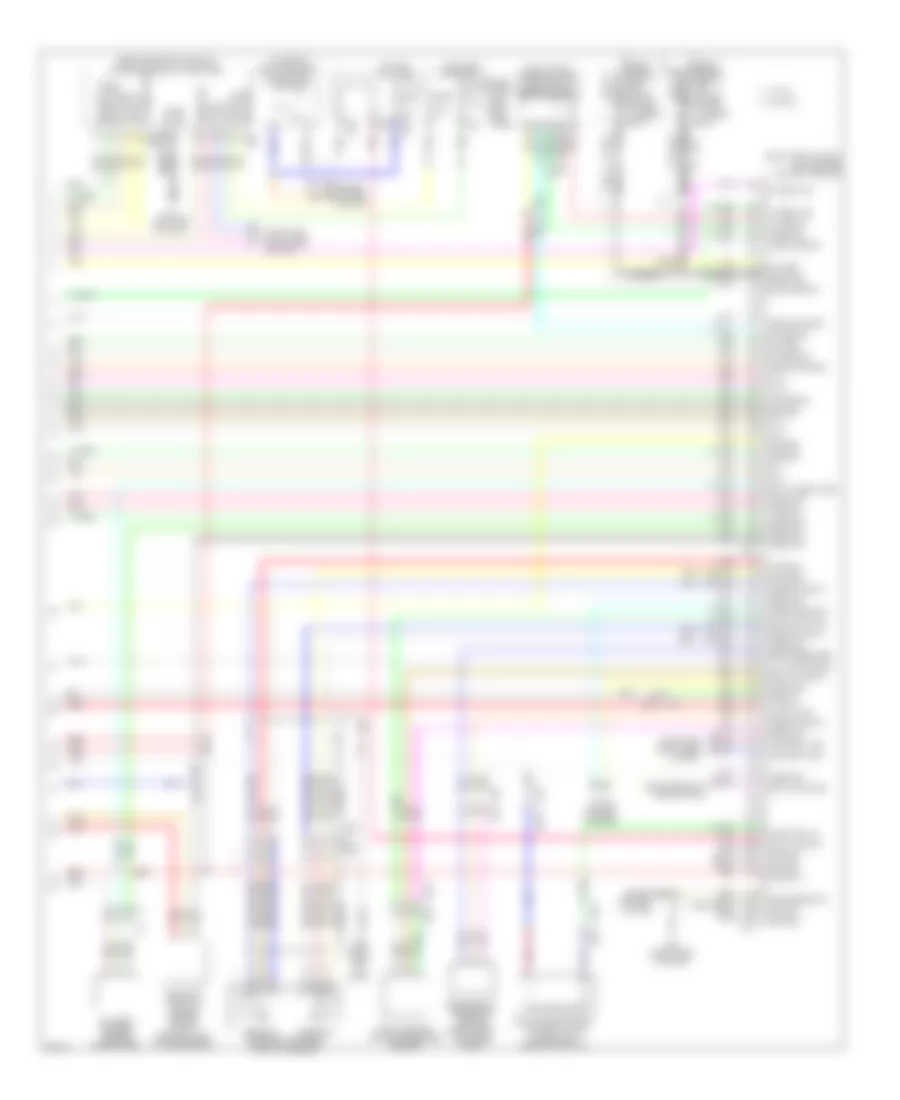
3.5L, Engine Performance Wiring Diagram (1 of 4) for Infiniti EX35 2012
 https://portal-diagnostov.com/license.html
Automotive Electricians Portal FZCO
Automotive Electricians Portal FZCO
https://portal-diagnostov.com/license.html
https://portal-diagnostov.com/license.html
Automotive Electricians Portal FZCO
Automotive Electricians Portal FZCO
List of elements for 3.5L, Engine Performance Wiring Diagram (1 of 4) for Infiniti EX35 2012:
- (front of right cylinder bank)
- (right front of engine) f34
- (top of left cylinder bank) ignition coil 2 (w/ power transistor)
- (top of left cylinder bank) ignition coil 4 (w/ power transistor)
- (top of left cylinder bank) ignition coil 6 (w/ power transistor)
- (top of right cylinder bank) condenser
- (top of right cylinder bank) ignition coil 1 (w/ power transistor)
- (top of right cylinder bank) ignition coil 3 (w/ power transistor)
- (top of right cylinder bank) ignition coil 5 (w/ power transistor)
- Af+1
- Af-1
- Afh1
- Afh2
- Close
- Crankshaft position sensor (pos) (right rear of engine)
- Cvtc 1
- Cvtc 2
- E phase 1
- E phase 2
- Ecm (engine control module) (right end of dash)
- Electric throttle control actuator (bank 2) (top left side of engine)
- Evap
- Evtc 1
- Evtc 2
- Exhaust valve timing control magnet retarder (bank 1) (front of right cylinder bank)
- Exhaust valve timing control magnet retarder (bank 2) (front of left cylinder bank)
- F101
- F102
- F104
- F105
- Fpr
- Gnd
- Gnd a(tps)
- Gnd pos
- Gnda intpres
- Ign 1
- Ign 2
- Ign 3
- Ign 4
- Ign 5
- Ign 6
- Ignsw
- Intake valve timing control solenoid valve (bank 1)
- Intake valve timing control solenoid valve (bank 2) (front of left cylinder bank)
- M95 (right side of dash)
- Motor b1 close
- Motor b1 open
- Motor2 close
- Motor2 open
- Motrly
- Mtr rly pwr sply b1
- Nca
- O2hr1
- O2hr2
- Open
- Phase 1
- Phase 2
- Plug spark
- Pnk
- Pos
- Red
- Sensor 1
- Sensor 2
- Snsr pwr sply
- Spark plug
- Ssoff
- Tan
- Throttle control motor
- Throttle position sensor
- Tps1 1
- Tps1 2
- Tps2 1
- Tps2 2
- Vmot2
3.5L, Engine Performance Wiring Diagram (2 of 4) for Infiniti EX35 2012
List of elements for 3.5L, Engine Performance Wiring Diagram (2 of 4) for Infiniti EX35 2012:
- A/t assembly (on transmission)
- Can h
- Can l
- Close
- Computer data lines system
- Cooling fans system
- Cpu
- E106
- E22 (right rear of engine compt)
- Ecm relay
- Electric throttle control actuator (bank 1) (top right side of engine)
- Evap canister purge volume control solenoid valve (top rear of engine)
- F103
- F104
- F105
- Fuel pump relay
- Fuse 10a
- Fuse 15a
- Hot at all times
- Ignition relay
- Ipdm e/r (intelligent power distribution module engine room) (right rear of engine compt)
- Joint connector
- M116
- Nca
- Open
- Pnk
- Red
- Sensor 1
- Sensor 2
- St rly
- Tan
- Tcm (transmission control module)
- Throttle control motor
- Throttle control motor relay
- Throttle position sensor
3.5L, Engine Performance Wiring Diagram (3 of 4) for Infiniti EX35 2012
List of elements for 3.5L, Engine Performance Wiring Diagram (3 of 4) for Infiniti EX35 2012:
- (1, 3 & 5: top of right cylinder bank) (2, 4 & 6: top of left cylinder bank) fuel injectors
- (left front of engine compt) mass air flow sensor (bank 2)
- (rear of right cylinder bank) exhaust valve timing control position sensor (bank 1)
- (top of fuel tank) fuel level sensor unit & fuel pump (main)
- Air fuel ratio (a/f) sensor 1 (bank 1) (right side of engine)
- Air fuel ratio (a/f) sensor 1 (bank 2) (left side of engine)
- B24 (left "c" pillar)
- Camshaft position sensor (phase) (bank 2) (rear of left cylinder bank)
- Combination meter
- Comm amp lcd
- Comm amp mtr
- Comm lcd amp
- Comm mtr amp
- E104
- E106
- Engine coolant temperature sensor (left rear of engine)
- Engine oil temperature sensor
- Exhaust valve timing control position sensor (bank 2) (rear of left cylinder bank)
- F1 e3
- F103
- F106
- F107
- Fuel pump
- Fuel tank temperature sensor
- Heated oxygen sensor 2 (bank 1) (left side of engine)
- Heated oxygen sensor 2 (bank 2) (left side of engine)
- M116
- M170 m134
- M95 (right side of dash)
- Nca
- Pnk
- Power steering control unit (right side of dash)
- Power steering pressure sensor
- Red
- Snow mode switch
- Tacho eng
- Tan
3.5L, Engine Performance Wiring Diagram (4 of 4) for Infiniti EX35 2012
List of elements for 3.5L, Engine Performance Wiring Diagram (4 of 4) for Infiniti EX35 2012:
- (behind center console) unified meter & a/c amplifier
- (on brake pedal bracket) stop lamp switch
- (or pnk)
- (or red)
- (right end of dash) ecm (engine control module)
- (right front of engine compt) mass air flow sensor (bank 1)
- A/f sen 1-b2
- Accelerator pedal position sensor
- Amp lcd
- Amp meter
- App sen 1
- App sen 2
- Ascd brake sw
- Ascd strng sw
- At snow sw
- B201
- Bat pwr
- Batt curent sen
- Battery current sensor (on battery)
- Camshaft position sensor (phase) (bank 1) (rear of right cylinder bank)
- Can comm line
- Can h
- Can l
- Computer data lines system
- Cruise control system
- Data link conn
- E103
- E106
- Ecm gnd
- Ect sen
- Eot sen
- Evap canister vent control valve (under right rear of vehicle)
- Evap con val
- Evap cont sys
- Evap control system pressure sensor
- F102
- F103
- F103 m116
- F201 f9
- Ful tnk tem sen
- Fuse 10a
- Fuse block (j/b) (left kick panel)
- Gnd
- Hed oxn sn2-b1
- Hed oxn sn2-b2
- Hot at all times
- Hot in on or start
- Iat sen b1
- Ign pwr
- Inj 1
- Inj 2
- Inj 3
- Inj 4
- Inj 5
- Inj 6
- Knock sen b1
- Knock sen b2
- Knock sensor (bank 1) (top center of right cylinder bank)
- Knock sensor (bank 2) (top center of left cylinder bank)
- Lcd amp
- Let sen b2
- M107
- M11 (left end of dash)
- M116
- M117
- M66
- M67
- M95 (right side of dash)
- Maf sen b1
- Maf sen b2
- Meter amp
- Output sig
- Pnk
- Pnp sig
- Psp sen
- Pwr sply
- Red
- Refri press sen
- Refrigerant pressure sensor (right front of engine compt)
- Sen gnd
- Sen powr sply
- Sens gnd
- Sensor 1
- Sensor 2
- Shield
- Snsr gnd
- Snsr pwr sply
- Stop lamp sw
- Tan
- W/ icc
- W/o icc

 Čeština
 Dansk
Dansk Deutsch
 Ελληνικά
 English
 Español
 Suomi
Suomi Français
 Français
 עברית
עברית Hrvatski
 Magyar
 Italiano
 日本語
日本語 한국어
한국어 Nederlands
 Polski
 Português
 Português
 Română
 Русский
 Slovenčina
 Slovenščina
 Svenska
 Türkçe
 中文 (中国)