ENGINE PERFORMANCE
4.5L
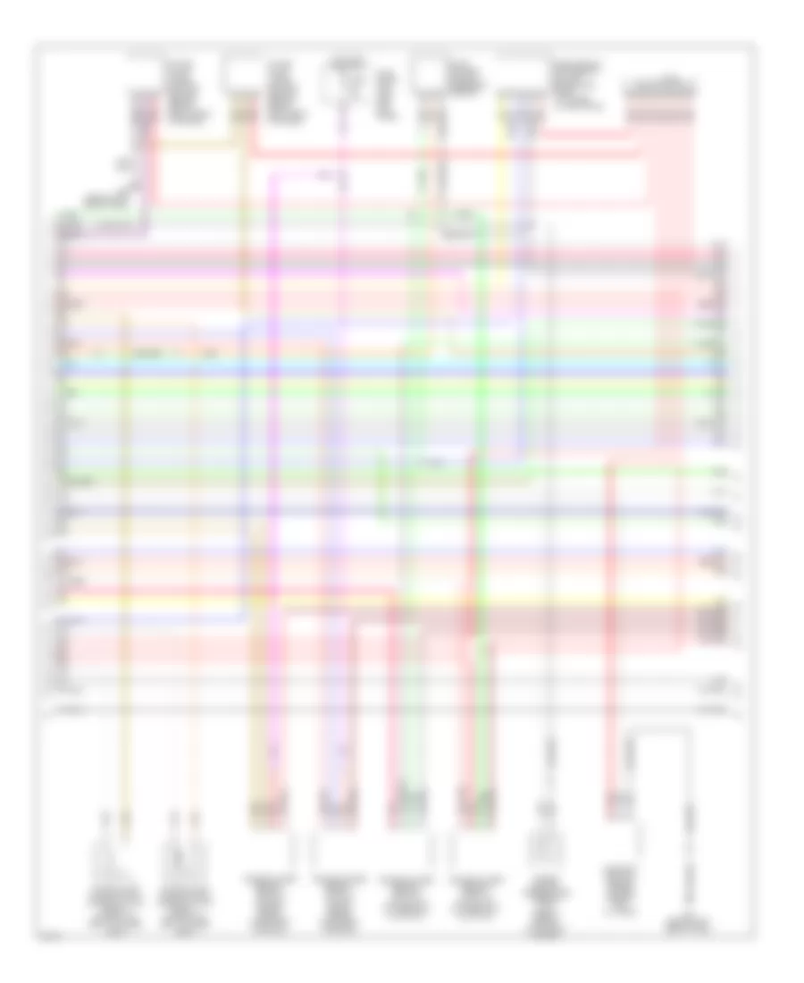
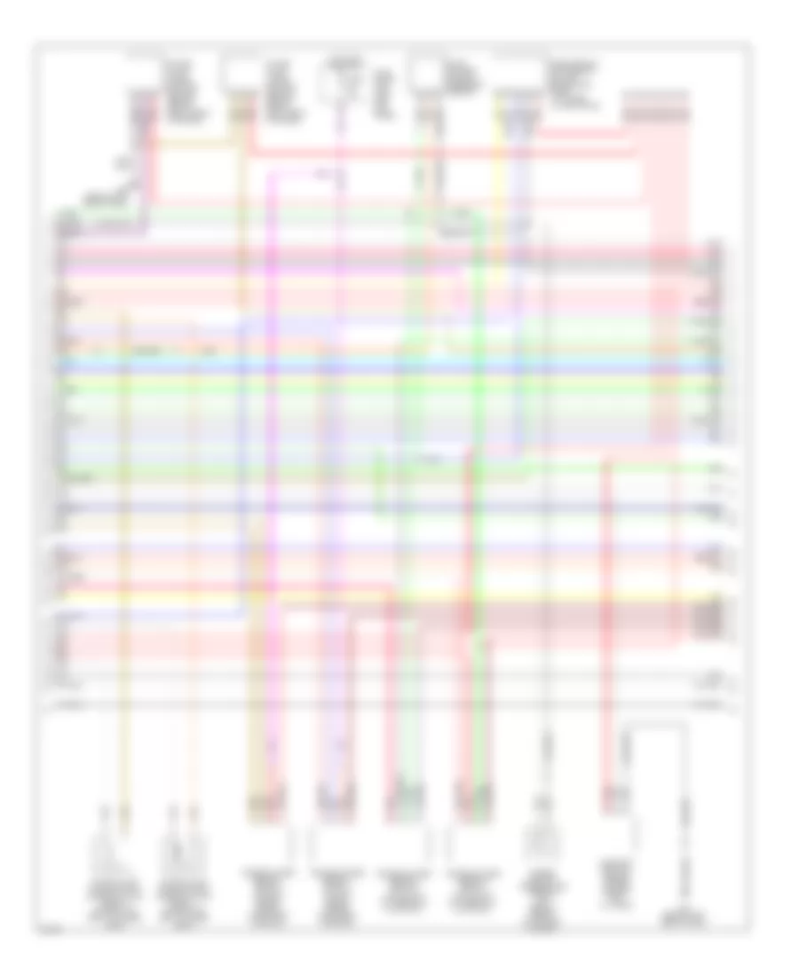
4.5L, Engine Performance Wiring Diagram, Early Production (1 of 4) for Infiniti FX45 2004
 https://portal-diagnostov.com/license.html
Automotive Electricians Portal FZCO
Automotive Electricians Portal FZCO
https://portal-diagnostov.com/license.html
https://portal-diagnostov.com/license.html
Automotive Electricians Portal FZCO
Automotive Electricians Portal FZCO
List of elements for 4.5L, Engine Performance Wiring Diagram, Early Production (1 of 4) for Infiniti FX45 2004:
- (behind left side of dash) m35
- 15a
- Avcc
- Avcc2
- C-ivc (l)
- C-ivc (r)
- Combination meter
- Engine control module (behind glove box)
- Evap
- F11 (at left side of eng compt)
- Ftrps
- Fuel injector
- Fuse 10a
- Fuse 15a
- Fuse block (j/b) (behind left kick panel)
- Gnd
- Hot in on or start
- Ign 7
- Ignition coil 1 (w/ power transistor)
- Ignition coil 2 (w/ power transistor)
- Ignition coil 3 (w/ power transistor)
- Ignition coil 4 (w/ power transistor)
- Ignition coil 5 (w/ power transistor)
- Ignition coil 6 (w/ power transistor)
- Ignition coil 7 (w/ power transistor)
- Ignition coil 8 (w/ power transistor)
- Inj 1
- Inj 2
- Inj 3
- Inj 4
- Inj 5
- Inj 6
- Ivc pus (r)
- Knk1
- Knk2
- Knock sensor (bank 1) (lower left side of cylinder block)
- Knock sensor (bank 2) (lower right side of cylinder block)
- M35 (behind left side of dash, left of steering column)
- Malfunction indicator lamp
- Motor1
- Motor2
- Nca
- Nca nca
- O2hfl
- O2hfr
- O2hrl
- O2hrr
- O2sfl
- O2sfr
- O2srl
- Pdpres
- Phase
- Plug spark
- Pnk
- Pos
- Ps pres
- Qa+
- Red
- Spark plug
- Tps1
- Unified meter control unit
- V mot
- Vias
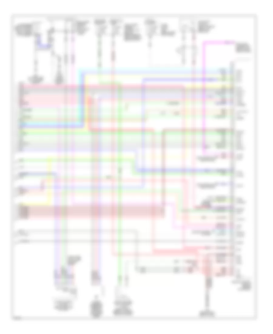
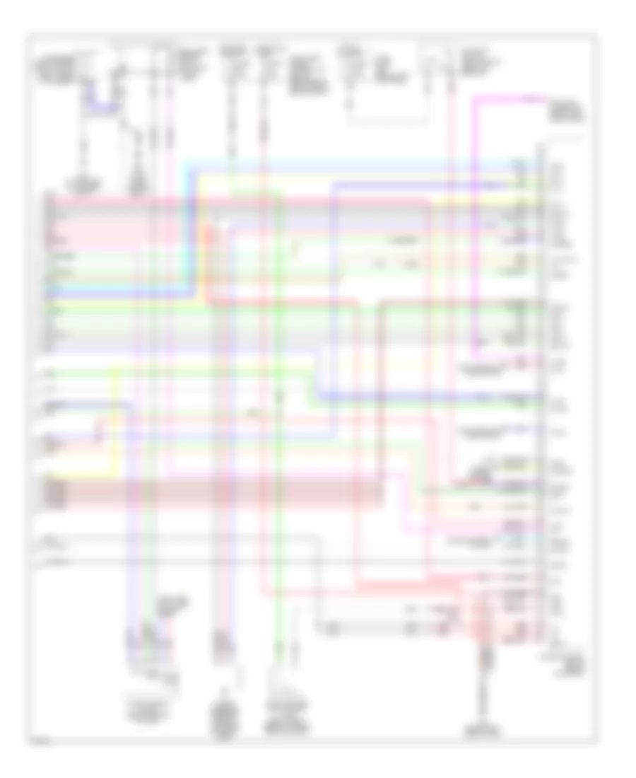
4.5L, Engine Performance Wiring Diagram, Early Production (2 of 4) for Infiniti FX45 2004
List of elements for 4.5L, Engine Performance Wiring Diagram, Early Production (2 of 4) for Infiniti FX45 2004:
- (at left side of eng compt, near ignition coil 1) f11
- (on top front of engine) vias control solenoid valve
- Accelerator pedal position (app) sensor (on pedal bracket)
- Condenser (behind upper right side of dash, taped to harness)
- Crankshaft position sensor (pos) (lower left front of cylinder block)
- E213
- Ecm relay
- Electric throttle control actuator (on left rear of engine)
- Evap canister purge volume control solenoid valve (on rear of intake manifold)
- F19
- Fuel pump relay
- Fuse 10a
- Fuse 15a
- Fuse 20a
- Hot at all times
- Hot in on or start
- Intelligent power distribution module (engine room) (right rear of engine compt)
- J/c 3
- M35 (behind left side of dash)
- M35 (behind left side of dash, left of steering column)
- Nca
- Pnk
- Red
- Refrigerant pressure sensor (right front of eng compt, near radiator filler neck)
- Sensor 1
- Sensor 2
- Throttle control motor
- Throttle control motor relay
- Throttle position (tp) sensor 1
- Throttle position (tp) sensor 2
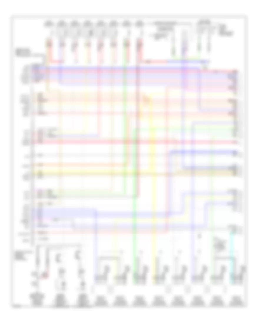
4.5L, Engine Performance Wiring Diagram, Early Production (3 of 4) for Infiniti FX45 2004
List of elements for 4.5L, Engine Performance Wiring Diagram, Early Production (3 of 4) for Infiniti FX45 2004:
- Camshaft position sensor (phase) (rear of left cyl head)
- Engine coolant temperature sensor (on rear of engine, on coolant outlet)
- Evap control system pressure sensor
- Fuse 10a
- Fuse block (j/b) (left left kick panel)
- Heated oxygen sensor 1 (bank 1) (on left side of engine, on exhaust manifold)
- Heated oxygen sensor 1 (bank 2) (on right side of engine, on exhaust manifold)
- Heated oxygen sensor 2 (bank 1) (on outlet of three way catalyst)
- Heated oxygen sensor 2 (bank 2) (on outlet of three way catalyst)
- Hot in on or start
- Intake valve timing control position sensor (bank 1) (left front of engine)
- Intake valve timing control position sensor (bank 2) (right front of engine)
- Intake valve timing control solenoid valve (bank 1) (on front of left cylinder head)
- Intake valve timing control solenoid valve (bank 2) (on front of right cylinder head)
- J/c 3
- M35 (behind left side of dash)
- Mass airflow (maf) sensor (on left side of eng, compt, attached to air intake)
- Pnk
- Red
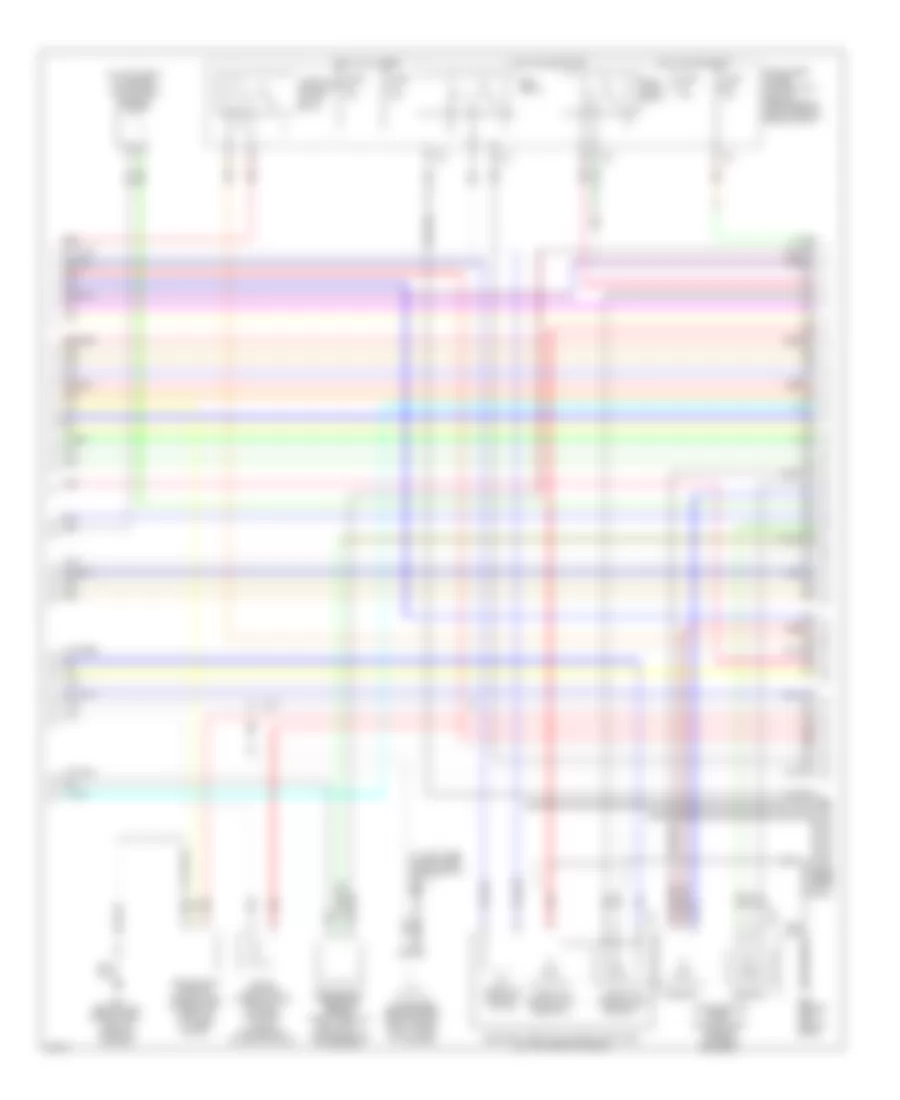
4.5L, Engine Performance Wiring Diagram, Early Production (4 of 4) for Infiniti FX45 2004
List of elements for 4.5L, Engine Performance Wiring Diagram, Early Production (4 of 4) for Infiniti FX45 2004:
- Aps1
- Aps2
- Ascdsw
- Avcc
- Avcc2
- B15 (on floor near driver's seat)
- B45 (at left side of luggage compt)
- Batt
- Bncsw
- Brake
- Can l
- Can-h
- Can-l
- Cdcv
- Computer data lines system
- Condenser (behind upper right side of dash, taped to harness)
- Cruise control system
- Data link connector (below left side of dash)
- Ecm
- Engine control module (behind glove box)
- Evap canister vent control valve (below right rear of vehicle, behind bumper)
- Fpr
- Fuel level sensor unit & fuel pump (in fuel tank)
- Fuse 10a
- Fuse 20a
- Fuse block (j/b) (behind left kick panel)
- Gnd
- Gnd 02
- Gnd a
- Gnd a2
- Grd
- Hot at all times
- Hot in on or start
- Ign 1
- Ign 2
- Ign 3
- Ign 4
- Ign 5
- Ign 6
- Ign 8
- Ign sw
- Inj 8
- Intelligent power distribution module (engine room) (right rear of engine compt)
- Ivc pus (l)
- J/c
- Kline
- M35 (behind left side of dash)
- Moyrly
- Nca
- Neut
- O2srr
- Pdpres
- Pnk
- Power steering pressure sensor (on power steering pump)
- Red
- Ssoff
- Stoplight switch (above brake pedal, on bracket)
- Tps2
- Unified meter & a/c amp (behind center of dash)
4.5L, Engine Performance Wiring Diagram, Late Production (1 of 4) for Infiniti FX45 2004
List of elements for 4.5L, Engine Performance Wiring Diagram, Late Production (1 of 4) for Infiniti FX45 2004:
- (behind left side of dash) m35
- 15a
- Avcc
- Avcc2
- C-ivc (l)
- C-ivc (r)
- Combination meter
- Engine control module (behind glove box)
- Evap
- F11 (at left side of eng compt)
- Ftrps
- Fuel injector
- Fuse 10a
- Fuse 15a
- Fuse block (j/b) (behind left kick panel)
- Gnd
- Hot in on or start
- Ign 7
- Ignition coil 1 (w/ power transistor)
- Ignition coil 2 (w/ power transistor)
- Ignition coil 3 (w/ power transistor)
- Ignition coil 4 (w/ power transistor)
- Ignition coil 5 (w/ power transistor)
- Ignition coil 6 (w/ power transistor)
- Ignition coil 7 (w/ power transistor)
- Ignition coil 8 (w/ power transistor)
- Inj 1
- Inj 2
- Inj 3
- Inj 4
- Inj 5
- Inj 6
- Ivc pus (r)
- Knk1
- Knk2
- Knock sensor (bank 1) (lower left side of cylinder block)
- Knock sensor (bank 2) (lower right side of cylinder block)
- M35 (behind left side of dash, left of steering column)
- Malfunction indicator lamp
- Motor1
- Motor2
- Nca
- Nca nca
- O2hfl
- O2hfr
- O2hrl
- O2hrr
- O2sfl
- O2sfr
- O2srl
- Pdpres
- Phase
- Plug spark
- Pnk
- Pos
- Ps pres
- Qa+
- Red
- Spark plug
- Tps1
- Unified meter control unit
- V mot
- Vias
4.5L, Engine Performance Wiring Diagram, Late Production (2 of 4) for Infiniti FX45 2004
List of elements for 4.5L, Engine Performance Wiring Diagram, Late Production (2 of 4) for Infiniti FX45 2004:
- (at left side of eng compt, near ignition coil 1) f11
- (on top front of engine) vias control solenoid valve
- Accelerator pedal position (app) sensor (on pedal bracket)
- Condenser (behind upper right side of dash, taped to harness)
- Crankshaft position sensor (pos) (lower left front of cylinder block)
- E213
- Ecm relay
- Electric throttle control actuator (on left rear of engine)
- Evap canister purge volume control solenoid valve (on rear of intake manifold)
- F19
- Fuel pump relay
- Fuse 10a
- Fuse 15a
- Fuse 20a
- Hot at all times
- Hot in on or start
- Intelligent power distribution module (engine room) (right rear of engine compt)
- M35 (behind left side of dash)
- M35 (behind left side of dash, left of steering column)
- Nca
- Pnk
- Red
- Refrigerant pressure sensor (right front of eng compt, near radiator filler neck)
- Sensor 1
- Sensor 2
- Throttle control motor
- Throttle control motor relay
- Throttle position (tp) sensor 1
- Throttle position (tp) sensor 2
4.5L, Engine Performance Wiring Diagram, Late Production (3 of 4) for Infiniti FX45 2004
List of elements for 4.5L, Engine Performance Wiring Diagram, Late Production (3 of 4) for Infiniti FX45 2004:
- Camshaft position sensor (phase) (rear of left cyl head)
- Engine coolant temperature sensor (on rear of engine, on coolant outlet)
- Evap control system pressure sensor
- Fuse 10a
- Fuse block (j/b) (left left kick panel)
- Heated oxygen sensor 1 (bank 1) (on left side of engine, on exhaust manifold)
- Heated oxygen sensor 1 (bank 2) (on right side of engine, on exhaust manifold)
- Heated oxygen sensor 2 (bank 1) (on outlet of three way catalyst)
- Heated oxygen sensor 2 (bank 2) (on outlet of three way catalyst)
- Hot in on or start
- Intake valve timing control position sensor (bank 1) (left front of engine)
- Intake valve timing control position sensor (bank 2) (right front of engine)
- Intake valve timing control solenoid valve (bank 1) (on front of left cylinder head)
- Intake valve timing control solenoid valve (bank 2) (on front of right cylinder head)
- M35 (behind left side of dash)
- Mass airflow (maf) sensor (on left side of eng, compt, attached to air intake)
- Pnk
- Red
4.5L, Engine Performance Wiring Diagram, Late Production (4 of 4) for Infiniti FX45 2004
List of elements for 4.5L, Engine Performance Wiring Diagram, Late Production (4 of 4) for Infiniti FX45 2004:
- Aps1
- Aps2
- Ascdsw
- Avcc
- Avcc2
- B15 (on floor near driver's seat)
- B45 (at left side of luggage compt)
- Batt
- Bncsw
- Brake
- Can l
- Can-h
- Can-l
- Cdcv
- Computer data lines system
- Condenser (behind upper right side of dash, taped to harness)
- Cruise control system
- Data link connector (below left side of dash)
- Ecm
- Engine control module (behind glove box)
- Evap canister vent control valve (below right rear of vehicle, behind bumper)
- Fpr
- Fuel level sensor unit & fuel pump (in fuel tank)
- Fuse 10a
- Fuse 20a
- Fuse block (j/b) (behind left kick panel)
- Gnd
- Gnd 02
- Gnd a
- Gnd a2
- Grd
- Hot at all times
- Hot in on or start
- Ign 1
- Ign 2
- Ign 3
- Ign 4
- Ign 5
- Ign 6
- Ign 8
- Ign sw
- Inj 8
- Intelligent power distribution module (engine room) (right rear of engine compt)
- Ivc pus (l)
- Kline
- M35 (behind left side of dash)
- Moyrly
- Nca
- Neut
- O2srr
- Pdpres
- Pnk
- Power steering pressure sensor (on power steering pump)
- Red
- Ssoff
- Stoplight switch (above brake pedal, on bracket)
- Tps2
- Unified meter & a/c amp (behind center of dash)

 Čeština
 Dansk
Dansk Deutsch
 Ελληνικά
 English
 Español
 Suomi
Suomi Français
 Français
 עברית
עברית Hrvatski
 Magyar
 Italiano
 日本語
日本語 한국어
한국어 Nederlands
 Polski
 Português
 Português
 Română
 Русский
 Slovenčina
 Slovenščina
 Svenska
 Türkçe
 中文 (中国)