ENGINE PERFORMANCE
3.5L HYBRID
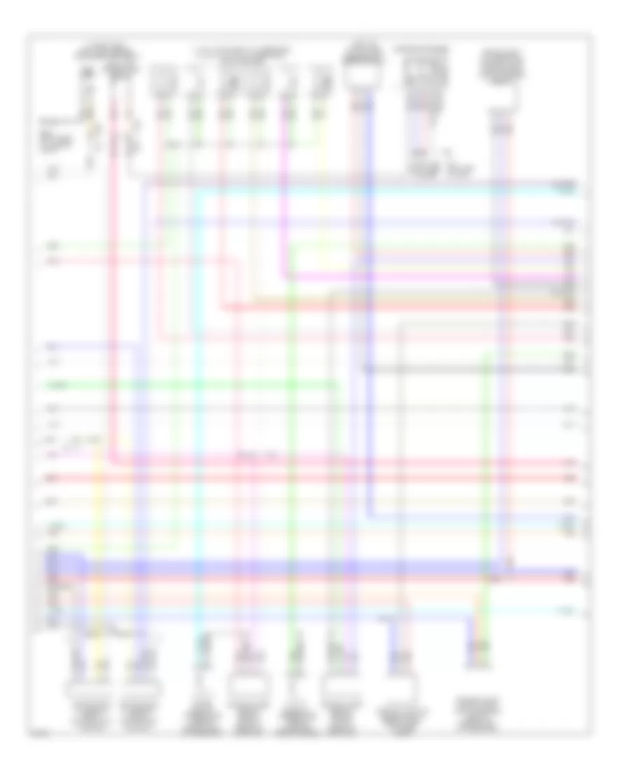
3.5L Hybrid, Engine Controls Wiring Diagram (1 of 5) for Infiniti M35h 2012
 https://portal-diagnostov.com/license.html
Automotive Electricians Portal FZCO
Automotive Electricians Portal FZCO
https://portal-diagnostov.com/license.html
https://portal-diagnostov.com/license.html
Automotive Electricians Portal FZCO
Automotive Electricians Portal FZCO
List of elements for 3.5L Hybrid, Engine Controls Wiring Diagram (1 of 5) for Infiniti M35h 2012:
- (front of engine) f34
- (front of right cylinder bank)
- (top of engine) condenser
- (top of left cylinder bank) ignition coil 2 (w/ power transistor)
- (top of left cylinder bank) ignition coil 4 (w/ power transistor)
- (top of left cylinder bank) ignition coil 6 (w/ power transistor)
- (top of right cylinder bank) ignition coil 1 (w/ power transistor)
- (top of right cylinder bank) ignition coil 3 (w/ power transistor)
- (top of right cylinder bank) ignition coil 5 (w/ power transistor)
- A/f sens1
- A/f-1
- Afh1
- Afh2
- Avcc phase 2
- Can-h
- Can-l
- Close
- Computer data lines system
- E phase 2
- E pos sens 1
- Ecm (engine control module) (right end of dash)
- Ecm gnd
- Electric throttle control actuator (bank 2) (left throttle body)
- Evap
- Evtc valve 1
- Evtc valve 2
- Exhaust valve timing control solenoid valve (bank 1) (front of right cylinder bank)
- Exhaust valve timing control solenoid valve (bank 2) (front of left cylinder bank)
- F101
- F102
- F103
- Fpr
- Gnd (tps1)
- Gnd pos
- Ign 1
- Ign 2
- Ign 3
- Ign 4
- Ign 5
- Ign 6
- Ignsw
- Intake valve timing control solenoid valve (bank 1)
- Intake valve timing control solenoid valve (bank 2) (front of left cylinder bank)
- Ivtc 1
- Ivtc 2
- M116
- M95 (right side of dash)
- Map sens
- Motor (close) 1
- Motor (open) 1
- Motor2 (close)
- Motor2 (open)
- Motrly1
- Nca
- O2hr1
- O2hr2
- Open
- Phase 1
- Phase 2
- Plug spark
- Pnk
- Pos
- Pow sup sen2
- Pss phase 1
- Red
- Sens gnd
- Sens pwr bcs
- Sens pwr tps 1
- Sens pwr tps 2
- Sensor 1
- Sensor 2
- Spark plug
- Ssoff
- Throttle control motor
- Throttle position sensor
- Tps1 1
- Tps1 2
- Tps2 1
- Tps2 2
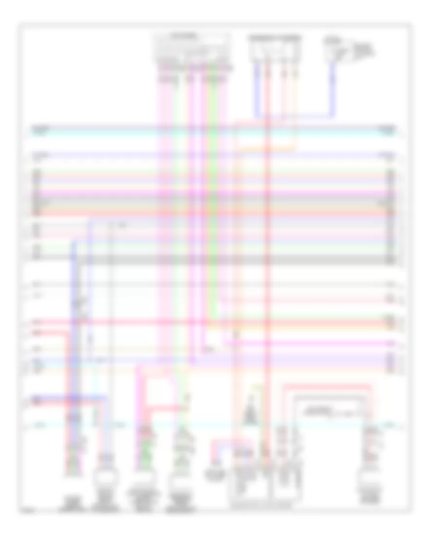
3.5L Hybrid, Engine Controls Wiring Diagram (2 of 5) for Infiniti M35h 2012
List of elements for 3.5L Hybrid, Engine Controls Wiring Diagram (2 of 5) for Infiniti M35h 2012:
- A/t assembly
- B37
- Can h
- Can l
- Close
- Computer data lines system
- Cpu
- Crankshaft position sensor (right rear of engine)
- E105
- E106
- E19
- E46 (right side of engine compt)
- Ecm relay
- Electric throttle control actuator (bank 1) (right throttle body)
- Evap canister purge volume control solenoid valve (top right rear of engine)
- F103
- Fuel pump relay
- Fuse 10a
- Fuse 15a
- Hot at all times
- Ignition relay
- Ipdm e/r (intelligent power distribution module engine room) (right rear of engine compt)
- Joint connector
- M116
- Nca
- Open
- Pnk
- Red
- Sensor 1
- Sensor 2
- Tcm (transmission control module)
- Throttle control motor
- Throttle control motor relay
- Throttle position sensor
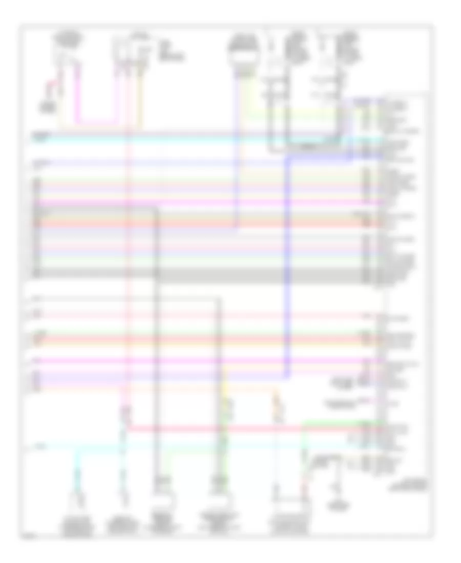
3.5L Hybrid, Engine Controls Wiring Diagram (3 of 5) for Infiniti M35h 2012
List of elements for 3.5L Hybrid, Engine Controls Wiring Diagram (3 of 5) for Infiniti M35h 2012:
- (1, 3 & 5: top of right cylinder bank) (2, 4 & 6: top left cylinder bank) fuel injectors
- (in fuel tank) fuel level sensor unit & fuel pump (main)
- (left air intake tube) mass air flow sensor (bank 2)
- (rear of right cylinder bank) exhaust valve timing control position sensor (bank 1)
- Air fuel ratio (a/f) sensor 1 (bank 1) (right exhaust manifold)
- Air fuel ratio (a/f) sensor 1 (bank 2) (left exhaust manifold)
- B201
- B224 (right rear of luggage compt)
- B230
- B51
- Camshaft position sensor (bank 2) (rear of left cylinder bank)
- Can-h
- Can-l
- Combination meter
- Computer data lines system
- Engine coolant temperature sensor (rear of left cylinder bank)
- Engine oil temperature sensor (lower right front of engine)
- Exhaust valve timing control position sensor (bank 2) (rear of left cylinder bank)
- F1 e3
- Fuel pump
- Fuel tank temperature sensor
- Gnd fuel sens
- Ground
- Heated oxygen sensor 2 (bank 1) (on right three way catalyst)
- Heated oxygen sensor 2 (bank 2) (on left three way catalyst)
- M11 (left side of dash)
- M117
- Malfunction ind lamp
- Nca
- Pnk
- Red
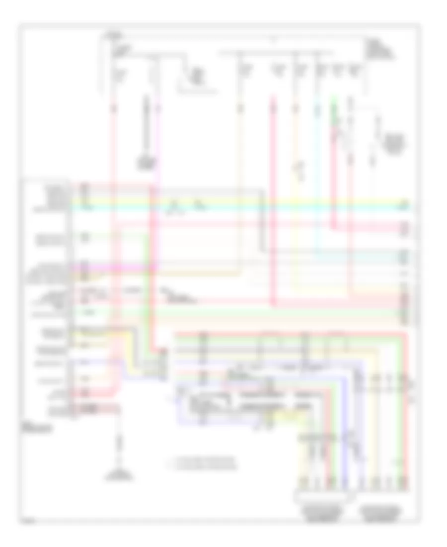
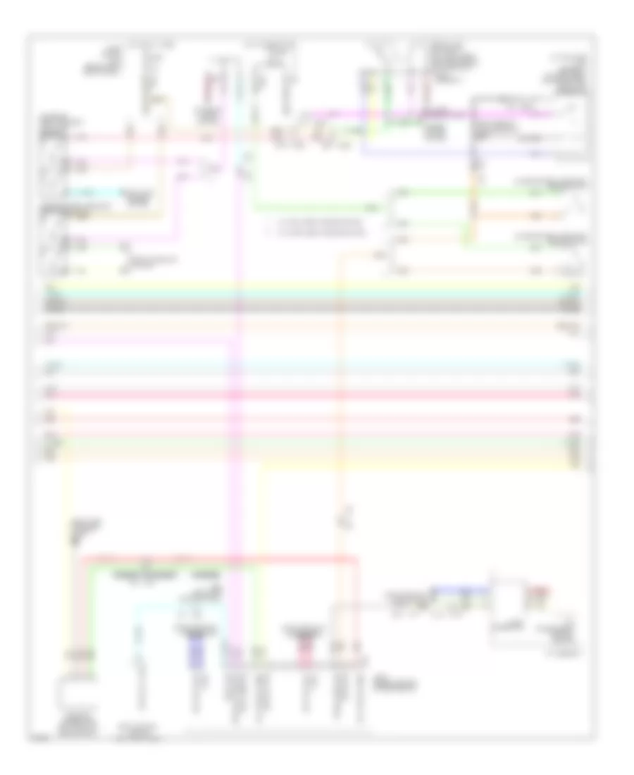
3.5L Hybrid, Engine Controls Wiring Diagram (4 of 5) for Infiniti M35h 2012
List of elements for 3.5L Hybrid, Engine Controls Wiring Diagram (4 of 5) for Infiniti M35h 2012:
- (left rear of luggage compt) c4
- B151
- B152
- B153
- B154
- B27
- B64 (left side of rear bumper)
- Battery current sensor (near battery)
- Battery terminal w/ fusible link
- C21
- Camshaft position sensor (bank 1) (rear of right cylinder bank)
- Can-h
- Can-l
- Computer data lines system
- E106
- Evap control system pressure sensor (under center rear of vehicle)
- F103
- Fusible link f 50a
- Gnd
- Hot at all times
- M116
- M12 b14
- M28
- M29
- M30
- Pcb harness
- Pnk
- Pow sup (bat)
- Pow sup (ign)
- Pump relay
- Red
- Refrigerant pressure sensor (right front of engine compt)
- Sub electric oil pump (left rear of engine)
- Sub electric oil pump inverter
- Sub electric oil pump relay
- Tan
- U-phase
- V-phase
- W-phase
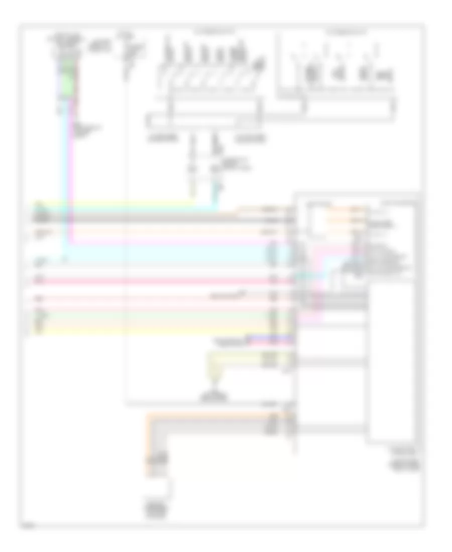
3.5L Hybrid, Engine Controls Wiring Diagram (5 of 5) for Infiniti M35h 2012
List of elements for 3.5L Hybrid, Engine Controls Wiring Diagram (5 of 5) for Infiniti M35h 2012:
- (on brake pedal bracket) stop lamp switch
- (right air intake tube) mass air flow sensor (bank 1)
- A/f sens 2
- Active noise control unit (w/o bose system) (left front of luggage compt)
- Avcc ftprs
- B44
- Batt cur sen
- Bose amp (w/ bose system) (left front of luggage compt)
- Brk sw
- Computer data lines system
- Cruise control system
- E103
- E115
- Ecm (engine control module) (right end of dash)
- Egn spd o/p sig
- Eng oil pr sens
- Engine oil pressure sensor (lower right front of engine)
- Evap canister vent control valve (on evap canister)
- Evap ctrl
- Evap sens
- F102
- F103
- F201 f9
- Fuel tnk ts
- Fuse 10a
- Fuse block (j/b) (behind left end of dash)
- Gnd
- Gnd (pha sen)
- Gnd o2 sens 2
- Gnd pos sen2
- Hot at all times
- Inj 1
- Inj 2
- Inj 3
- Inj 4
- Inj 5
- Inj 6
- Kline
- Knk1
- Knk2
- Knock sensor (bank 1) (top center of right cylinder bank)
- Knock sensor (bank 2) (top center of left cylinder bank)
- M107
- M116
- M77
- M95 (right side of dash)
- Manifold absolute pressure (map) sensor (left rear of intake manifold)
- Map sen
- Mass af sens1
- Mass af sens2
- O2sr2
- Pnk
- Pwr sply
- Red
- Ref pre sens
- Sens gnd
- Sens gnd2
- Shield
- Sps (maf san)
- Stp lp sw
- Ta1
- Tacho
- Tan
- Temp sens
- Vehcan h1
- Vehcan l1
3.5L Hybrid, Hybrid System Wiring Diagram (1 of 4) for Infiniti M35h 2012
List of elements for 3.5L Hybrid, Hybrid System Wiring Diagram (1 of 4) for Infiniti M35h 2012:
- Accelerator pedal position (app) sensor (on accelerator pedal bracket)
- App sens 1
- App sens 2
- Ascd/icc str sw
- B158
- B24 (left rear quarterpanel)
- B37
- B44
- B61 (left side of rear bumper)
- B69
- Batt vol
- Battery cooling fan relay (left "c" pillar)
- Clutch 1 stroke sens
- Dc/dc con act sig
- Dc/dc con volt
- Dc/dc sig
- E106 m6
- E119
- E19
- Fuse & fusible link block 3 (on battery positive post)
- Fuse 10a
- Fuse 20a
- Fusible link y 50a
- Hot at all times
- Hpcm (behind center of rear seats)
- Hpcm gnd
- Ign sig
- M150
- M151
- M77
- Nca
- Pnk
- Pwr sply from hpcm
- Red
- Self shut off relay
- Self shut off rly
- Sens gnd
- Sens gng
- Sens pwr sply
- Sensor gnd
- Shield
- Stabilizer sig
- Sys main rly 1
- Sys main rly 2
- W/ intelligent cruise control
- W/o intelligent cruise control
3.5L Hybrid, Hybrid System Wiring Diagram (2 of 4) for Infiniti M35h 2012
List of elements for 3.5L Hybrid, Hybrid System Wiring Diagram (2 of 4) for Infiniti M35h 2012:
- (+)
- (-)
- B24 (left rear quarterpanel)
- B37
- B44 m77
- C16
- C17
- Can-h
- Can-l
- Computer data lines system
- Detection connection
- E106
- E19
- E46 (right side of engine compt)
- E78
- F77
- Fuse 10a
- Gnd
- Hot in on or start
- Ipdm e/r (intelligent power distribution module engine room (right rear of engine compt)
- Nca
- Pnk
- Power sply
- Red
- Resolver sig r1 traction mtr
- Resolver sig r2 traction mtr
- Resolver sig s1 traction mtr
- Resolver sig s2 traction mtr
- Resolver sig s3 traction mtr
- Resolver sig s4 traction mtr
- Sens gnd
- Shield
- Temp snsr traction mtr
- Traction motor (rear of engine)
- Traction motor inverter (right rear of engine compt)
- U-phase
- V-phase
- W-phase
3.5L Hybrid, Hybrid System Wiring Diagram (3 of 4) for Infiniti M35h 2012
List of elements for 3.5L Hybrid, Hybrid System Wiring Diagram (3 of 4) for Infiniti M35h 2012:
- (at high stop lamp assembly) (w/ intelligent cruise control) stop lamp off relay 2
- (on brake pedal bracket) brake switch
- (on brake pedal bracket) stop lamp switch
- (right rear of luggage compt) b224
- (right side of engine compt) e46
- A/t assembly
- Anti-lock brakes system
- B159
- B201
- B228
- B24 (left rear quarterpanel)
- B28
- B37
- B44
- B5 b222
- Body control module (left kick panel)
- Brake sw
- Can-h
- Can-l
- Computer data lines system
- Cruise control system
- E103
- E119 b69
- E19
- E19 b37
- Electric water pump (left front of engine compt)
- Eltc water pump
- Exterior lights system
- F103
- Fuse 10a
- Fuse block (j/b) (behind left end of dash)
- Hev sys can-h
- Hev sys can-l
- Hot at all times
- Hot in on or start
- Hpcm (behind center of rear seats)
- Inter lock sw sig
- Joint connector
- M116
- M117
- M77
- Pnk
- Ready sig
- Red
- Service plug
- Shield
- Shift interlock system
- Start rly cont
- Stop lamp off relay 1 (w/ intelligent cruise control) (at high stop lamp assembly)
- Stop lamp sw
- Tcm (transmission control module)
- Trans range sw
- W/ intelligent cruise control
- W/o intelligent cruise control
3.5L Hybrid, Hybrid System Wiring Diagram (4 of 4) for Infiniti M35h 2012
List of elements for 3.5L Hybrid, Hybrid System Wiring Diagram (4 of 4) for Infiniti M35h 2012:
- (top of li-ion battery assembly) cooling fan battery
- Activate sig
- Air con seat rly
- Assistance switch
- B160
- B224 (right rear of luggage compt)
- B245
- B301
- B304
- B33
- B460
- B461
- B64 (left side of rear bumper)
- Battery terminal w/ fusible link
- C13
- Cancel switch
- Coast switch
- Colling mode req sig
- Combination switch (spiral cable)
- Computer data lines system
- Dc/dc converter
- Distance switch
- Dynamic driver
- Electric compressor (left side of engine)
- Fusible link a 250a
- Gnd
- Hi volt (+)
- Hi volt (-)
- Hi volt for precharge (+)
- Hot at all times
- Icc steering switch
- Ign
- Junction box
- Li-ion battery (under luggage compt floor)
- Li-ion battery controller
- M303
- M36
- Main
- Nca
- On/off switch
- Pnk
- Pre charge sig
- Pwr sply
- Red
- Resume/ accelerate switch
- Resume/accel switch
- Seats system
- Set/
- Shield
- Switch off) (on/
- Switch set/coast
- Volt stablizer sig
- W/ intelligent cruise control
- W/o intelligent cruise control

 Čeština
 Dansk
Dansk Deutsch
 Ελληνικά
 English
 Español
 Suomi
Suomi Français
 Français
 עברית
עברית Hrvatski
 Magyar
 Italiano
 日本語
日本語 한국어
한국어 Nederlands
 Polski
 Português
 Português
 Română
 Русский
 Slovenčina
 Slovenščina
 Svenska
 Türkçe
 中文 (中国)