ENGINE PERFORMANCE
4.5L
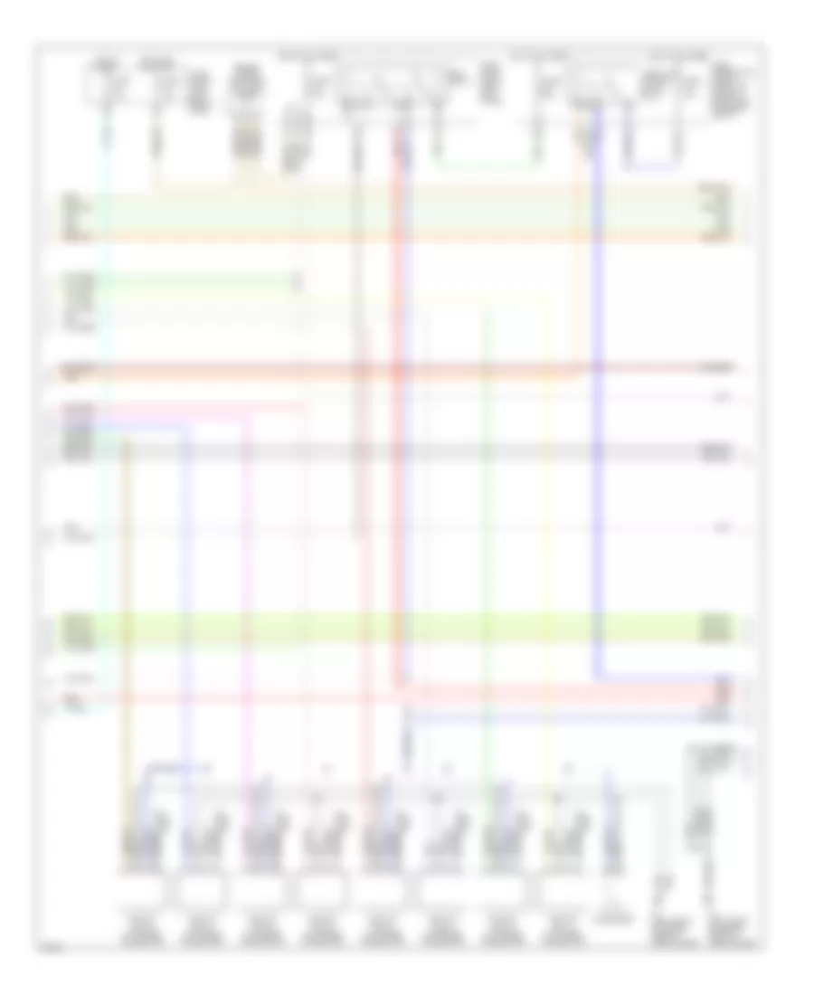
4.5L, Engine Performance Wiring Diagram (1 of 5) for Infiniti M45 2004
 https://portal-diagnostov.com/license.html
Automotive Electricians Portal FZCO
Automotive Electricians Portal FZCO
https://portal-diagnostov.com/license.html
https://portal-diagnostov.com/license.html
Automotive Electricians Portal FZCO
Automotive Electricians Portal FZCO
List of elements for 4.5L, Engine Performance Wiring Diagram (1 of 5) for Infiniti M45 2004:
- (behind upper left end of dash) j/c 10
- (behind upper right side of dash)
- A/c system
- Acrly
- Ascd control unit (behind dash, left of steering column)
- Combination meter
- Cooling fan speed control solenoid valve (on front of engine)
- Crankshaft position sensor (pos) (bottom rear of engine)
- Crtn
- Cvbv
- Dual mode muffler control unit (at right of luggage compt)
- Engine control module (ecm) (behind glove box)
- Etc prun
- Evap
- Evap canister purge volume control solenoid valve (under rear of vehicle, on evap canister)
- F8 (left front of engine, near oil level gauge)
- Fpcm
- Fpr
- Fuel injector
- Fuse 10a
- Fuse block (j/b) 1 (left end of dash)
- Hot in on or start
- Ign 1
- Ign 2
- Ign 3
- Ign 4
- Ign 5
- Ign 6
- Ign 7
- Ign 8
- Ignsw
- Inj 1
- Inj 2
- Inj 3
- Inj 4
- Inj 5
- Inj 6
- Inj 7
- Inj 8
- J/c
- J/c 19 (behind upper right side of dash)
- J/c 28
- Led
- Malfunction indicator lamp
- Motrly
- Nca
- O2hfl
- O2hfr
- O2hrl
- O2hrr
- Pnk
- Pos
- Power steering control unit (behind right side of dash)
- Prf+
- Prf-
- Prun in
- Red
- Ssoff
- Stsw
- Tacho
- Tp in
- Tvo0
- Unified meter control unit
- Vacuum cut valve bypass valve (under rear of vehicle, forward of evap canister)
- Vias
- Vias control solenoid valve (top front center of engine)
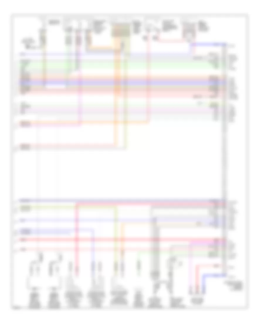
4.5L, Engine Performance Wiring Diagram (2 of 5) for Infiniti M45 2004
List of elements for 4.5L, Engine Performance Wiring Diagram (2 of 5) for Infiniti M45 2004:
- (behind upper right side of dash) j/c 19
- 22r
- Condenser
- Ecm relay
- F8 (left front of engine, near oil level gauge)
- F9 (left front of engine, near oil level gauge)
- Fuse 10a
- Fuse 15a
- Fuse 20a
- Fuse block (j/b) 1 (left end of dash)
- Fuse block (j/b) 2 (right kick panel)
- Fuse, fusible link & relay block (j/b) (in right front side of engine compt)
- Hot at all times
- Hot in on or start
- Hot in start
- Ignition coil 1 (w/ power transistor)
- Ignition coil 2 (w/ power transistor)
- Ignition coil 3 (w/ power transistor)
- Ignition coil 4 (w/ power transistor)
- Ignition coil 5 (w/ power transistor)
- Ignition coil 6 (w/ power transistor)
- Ignition coil 7 (w/ power transistor)
- Ignition coil 8 (w/ power transistor)
- Nca
- Plug spark
- Red
- Spark plug
- Throttle control motor relay
4.5L, Engine Performance Wiring Diagram (3 of 5) for Infiniti M45 2004
List of elements for 4.5L, Engine Performance Wiring Diagram (3 of 5) for Infiniti M45 2004:
- (behind upper right side of dash) j/c 30
- 33r
- 34r
- Camshaft position sensor (phase) (on front of left cyl head)
- F8 (left front of engine, near oil level gauge)
- Fuel pump relay
- Fuse 10a
- Fuse 15a
- Fuse block (j/b) 1 (left end of dash)
- Fuse block (j/b) 2 (right kick panel)
- Fuse, fusible link & relay block (j/b) (in right front side of engine compt)
- Heated oxygen sensor 1 (bank 1) (on inlet of left manifold twc)
- Heated oxygen sensor 1 (bank 2) (on inlet of right manifold twc)
- Heated oxygen sensor 2 (bank 1) (on outlet of left manifold twc)
- Heated oxygen sensor 2 (bank 2) (on outlet of right manifold twc)
- Hot at all times
- Hot in on or start
- Intake valve timing control position sensor (bank 1) (on front of left cyl head)
- Intake valve timing control position sensor (bank 2) (on front of right cyl head)
- J/c
- Nca
- Pnk
- Radiator coolant temperature sensor (bottom left side of radiator)
- Red
- Refrigerant pressure sensor (front right side of engine compt, near condenser)
4.5L, Engine Performance Wiring Diagram (4 of 5) for Infiniti M45 2004
List of elements for 4.5L, Engine Performance Wiring Diagram (4 of 5) for Infiniti M45 2004:
- (at right front door sill)
- Accelerator pedal position (app) sensor 1
- Accelerator pedal position (app) sensor 2
- Aps1
- Avcc2
- B217
- Batt
- Condenser
- Electric throttle control actuator
- Engine control module (ecm) (behind glove box)
- Engine coolant temperature sensor (on top rear of engine)
- Evap control system pressure sensor (under right rear side of vehicle)
- F8 (left front of engine, near oil level gauge)
- Fuel pump control module (fpcm) (on right side of luggage compt)
- Gnd a
- Gnd a2
- Ivcpusl
- Ivcpusr
- J/c
- J/c 28
- J/c 29 (behind upper right side of dash)
- Mass airflow (maf) sensor (between air duct & air cleaner housing)
- Nca
- Neut
- Pdpres
- Phase
- Pnk
- Power steering pressure (psp) sensor (lower right side of engine)
- Qa+
- Red
- Starting/ charging system
- Throttle control motor
- Throttle position (tp) sensor 1
- Throttle position (tp) sensor 2
- Tps2
4.5L, Engine Performance Wiring Diagram (5 of 5) for Infiniti M45 2004
List of elements for 4.5L, Engine Performance Wiring Diagram (5 of 5) for Infiniti M45 2004:
- (at left front door sill) b17
- Aps2
- Avcc
- Brksw
- Can h
- Can l
- Cdcv
- Computer data lines system
- Dropping resistor
- Engine control module (ecm) (behind glove box)
- Evap canister vent control valve (under rear of vehicle, on evap canister)
- F8 (left front of engine,
- F9 (left front of engine,
- Fgauge+
- Fgauge-
- Fpcmck
- Ftprs
- Fuel level sensor unit & fuel pump (in fuel tank)
- Gnd c
- Gnd e
- Gnd m
- Im lime
- Intake valve timing control solenoid valve (bank 1) (on top front of left cyl head)
- Intake valve timing control solenoid valve (bank 2) (on top front of right cyl head)
- Ivcl
- Ivcr
- J/c
- J/c 15 (behind upper right side of dash)
- J/c 7 (behind upper left side of dash)
- Kline
- Knk1
- Knk2
- Knock sensor (bank 1) (below left side of intake manifold)
- Knock sensor (bank 2) (below right side of intake manifold)
- Motor 1
- Motor 2
- Nats immu (behind dash, left of steering column)
- Nca
- Near oil level gauge)
- O2sfl
- O2sfr
- O2srl
- O2srr
- Pnk
- Pspres
- Qa-
- Red
- Stop lamp switch (on bracket, above brake pedal)
- Tps1
- Tvo0
- Twrf
- Vmot

 Čeština
 Dansk
Dansk Deutsch
 Ελληνικά
 English
 Español
 Suomi
Suomi Français
 Français
 עברית
עברית Hrvatski
 Magyar
 Italiano
 日本語
日本語 한국어
한국어 Nederlands
 Polski
 Português
 Português
 Română
 Русский
 Slovenčina
 Slovenščina
 Svenska
 Türkçe
 中文 (中国)