ENGINE PERFORMANCE
3.3L
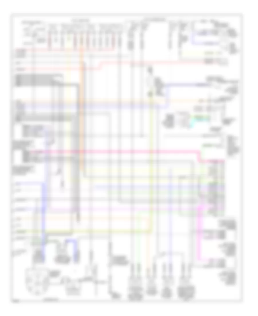
3.3L, Engine Performance Wiring Diagrams (1 of 2) for Infiniti QX4 1997
 https://portal-diagnostov.com/license.html
Automotive Electricians Portal FZCO
Automotive Electricians Portal FZCO
https://portal-diagnostov.com/license.html
https://portal-diagnostov.com/license.html
Automotive Electricians Portal FZCO
Automotive Electricians Portal FZCO
List of elements for 3.3L, Engine Performance Wiring Diagrams (1 of 2) for Infiniti QX4 1997:
- (for consult)
- (for gst)
- (left rear of cargo area)
- (lower left dash panel)
- (rear of engine) g115
- (right side of eng)
- A/c system
- Absolute pressure sensor (on left front fender well)
- All times
- Closed
- Crank- shaft position sensor (in distributor)
- Data link connector
- Eccs relay (right side of eng compt, in relay box 2)
- Egr temper- ature sensor (left rear of eng)
- Engine control module (ecm) (behind center of dash)
- Engine coolant temperature sensor (top front of eng)
- Evap canister purge volume control valve (rear of left front fender well)
- Evap control system pressure sensor (near fuel tank)
- Fuse 7.5a
- Fuse 10a
- Fuse 7.5a
- Fuse block (j/b)
- Fusible link & fuse box
- G120
- G200 (left kick panel)
- G404
- Hot at
- Hot at all times
- Hot in start
- Instrument cluster system
- Intake air temperature sensor (left front of engine compt)
- J/c (behind center of dash)
- Knock sensor (top rear of eng)
- Mass air flow sensor (on air intake assembly)
- Nca
- Pnk
- Power steering oil pressure switch (lower right front of eng compt)
- Tank fuel temperature sensor (in fuel tank)
- Throttle position sensor (on throttle body)
- Throttle position switch (on throttle body)
- Transmission system
- Transmissions system
- Wide open
3.3L, Engine Performance Wiring Diagrams (2 of 2) for Infiniti QX4 1997
List of elements for 3.3L, Engine Performance Wiring Diagrams (2 of 2) for Infiniti QX4 1997:
- (in relay box 2) inhibitor relay
- 13u
- 14u
- 19u
- 1o1
- 31u
- 43u
- Acc
- Camshaft position sensor
- Condenser (top right of eng, taped to harness)
- Distributor
- Egr solenoid valve (left front of eng)
- Electronic speedo- meter
- Engine control module (ecm) (behind center of dash)
- Evap canister purge control solenoid valve (rear of left front fender well)
- Evap canister vent control valve (left rear of vehicle, near fuel tank)
- Fuel injectors
- Fuel pump (in fuel tank)
- Fuel pump relay (in relay box 2)
- Fuse 10a
- Fuse block (j/b)
- Fuse fuse fuse 15a 15a 15a
- G101 (front of right front fender)
- G115 (rear of engine)
- G404 (left rear of cargo area)
- Hot at all times
- Hot in on or start
- Iacv-acc valve (right rear of eng)
- Ignition coil
- Ignition switch
- Instrument cluster
- Left front heated oxygen sensor (left side of exhaust manifold)
- Malfunction indicator
- Map/ baro switch solenoid valve (left front off eng)
- Nca
- Off
- Power transistor
- Resistor (top right side of eng, taped to harness)
- Right front heated oxygen sensor (right side of exhaust manifold)
- Right rear heated oxygen sensor (on right catalytic converter)
- Start
- Vacuum cut valve bypass valve (left rear of vehicle, near fuel tank)
- Vehicle speed sensor (right side of trans- mission)

 Čeština
 Dansk
Dansk Deutsch
 Ελληνικά
 English
 Español
 Suomi
Suomi Français
 Français
 עברית
עברית Hrvatski
 Magyar
 Italiano
 日本語
日本語 한국어
한국어 Nederlands
 Polski
 Português
 Português
 Română
 Русский
 Slovenčina
 Slovenščina
 Svenska
 Türkçe
 中文 (中国)