ENGINE PERFORMANCE
3.0L
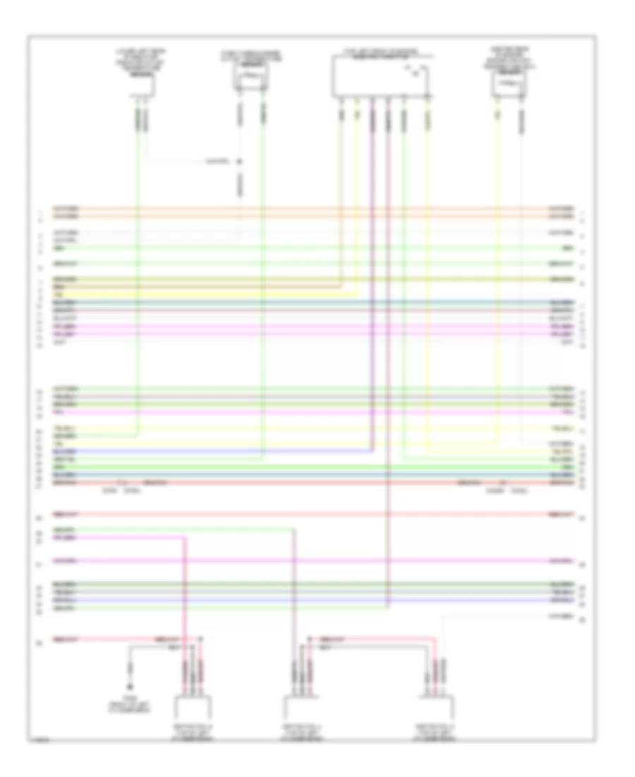
3.0L, Engine Performance Wiring Diagram (1 of 9) for Land Rover Discovery 4 HSE Lux 2014
 https://portal-diagnostov.com/license.html
Automotive Electricians Portal FZCO
Automotive Electricians Portal FZCO
https://portal-diagnostov.com/license.html
https://portal-diagnostov.com/license.html
Automotive Electricians Portal FZCO
Automotive Electricians Portal FZCO
List of elements for 3.0L, Engine Performance Wiring Diagram (1 of 9) for Land Rover Discovery 4 HSE Lux 2014:
- (top of left cylinder bank) fuel injector 4
- (top of left cylinder bank) fuel injector 5
- (top of right cylinder bank) fuel injector 1
- (top of right cylinder bank) fuel injector 3
- C0634
- Capacitor (top rear of engine)
- Engine control module (ecm) (right side of engine compt)
- G r railps
- G-r-cas1
- G-r-cas2
- G-r-sen
- G-r-tva
- I a radwts
- I f crash
- I-a-bts
- I-a-cacts
- I-a-engts
- I-a-fts
- I-a-imps
- I-a-tva1
- I-a-tva2
- I-p-caseb
- I-p-casia
- I-p-casib
- I-t-ocs
- Ign coil 1
- Ign coil 3
- Ign coil 4
- Ign coil 6
- Ignition coil 1 (top of right cylinder bank)
- Ignition coil 2 (top of right cylinder bank)
- Ignition coil 3 (top of right cylinder bank)
- Inj hs cyl 1a
- Inj hs cyl 1b
- Inj hs cyl 2b
- Inj hs cyl 3a
- Inj ls cyl 1a
- Inj ls cyl 1b
- Inj ls cyl 2b
- Inj ls cyl 3a
- O v 5vbps
- O v 5vrailps
- O-s-isf4
- O-s-lsfh1
- O-s-lsfh2
- O-t-caseca
- O-t-casecb
- O-t-casica
- O-t-casicb
- O-t-pcsv
- O-v-5vcasa
- O-v-5vcasb
- O-v-5vtva
- Oil level sensor (left side of oil pan)
- Pi080 (front of right cylinder bank)
- Pi081 (rear of right cylinder bank)
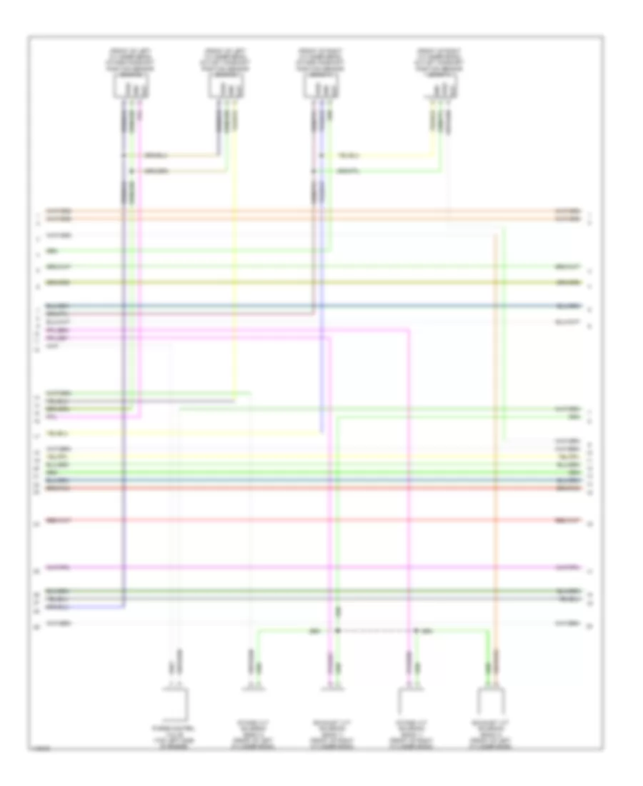
3.0L, Engine Performance Wiring Diagram (2 of 9) for Land Rover Discovery 4 HSE Lux 2014
List of elements for 3.0L, Engine Performance Wiring Diagram (2 of 9) for Land Rover Discovery 4 HSE Lux 2014:
- (center rear of engine) engine coolant temperature (ect) sensor
- (lower left rear of radiator) radiator outlet temperature sensor
- (top left front of engine) electric throttle
- C2763l c2764
- C3424l
- C3425m
- Fixed turbocharger outlet temperature sensor
- Ignition coil 4 (top of left cylinder bank)
- Ignition coil 5 (top of left cylinder bank)
- Ignition coil 6 (top of left cylinder bank)
- Pi082 (front of left cylinder bank)
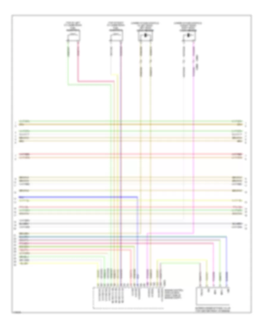
3.0L, Engine Performance Wiring Diagram (3 of 9) for Land Rover Discovery 4 HSE Lux 2014
List of elements for 3.0L, Engine Performance Wiring Diagram (3 of 9) for Land Rover Discovery 4 HSE Lux 2014:
- (front of left cylinder bank) intake camshaft position sensor (bank 2)
- (front of left cylinder bank) outlet camshaft position sensor (bank 2)
- (front of right cylinder bank) intake camshaft position sensor (bank 1)
- (front of right cylinder bank) outlet camshaft position sensor (bank 1)
- Exhaust vvt solenoid (bank 1) (front of right cylinder bank)
- Exhaust vvt solenoid (bank 2) (front of left cylinder bank)
- Gnd
- Intake vvt solenoid (bank 1) (front of right cylinder bank)
- Intake vvt solenoid (bank 2) (front of left cylinder bank)
- Out
- Purge control valve (top left side of engine)
- Vref
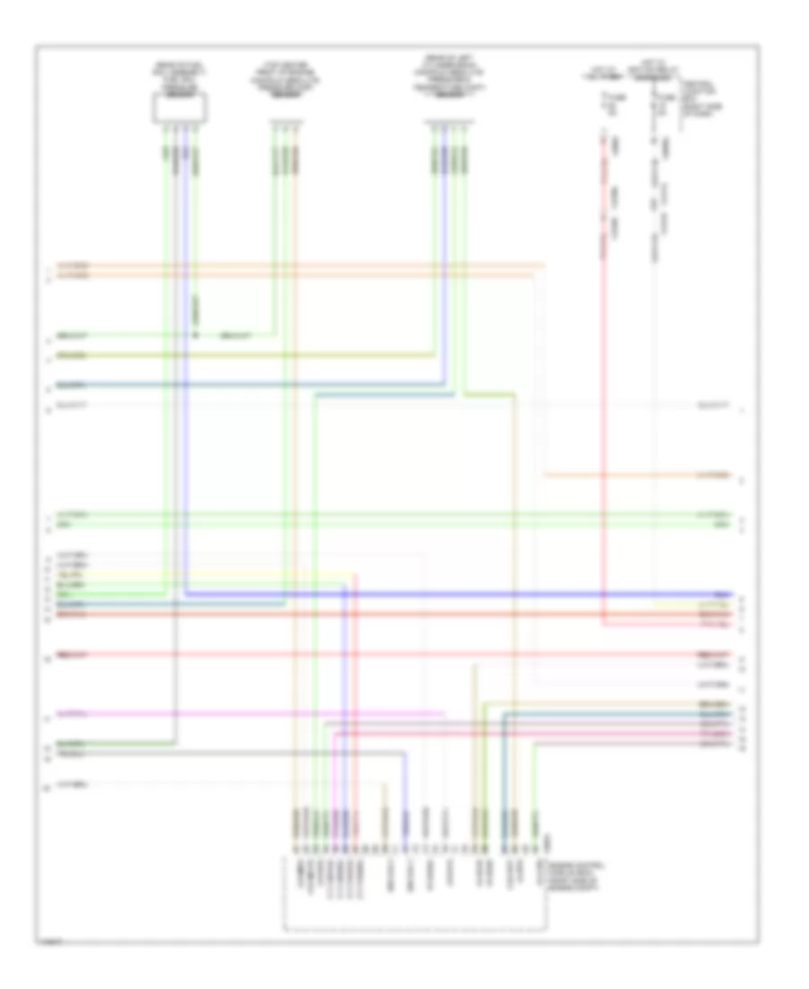
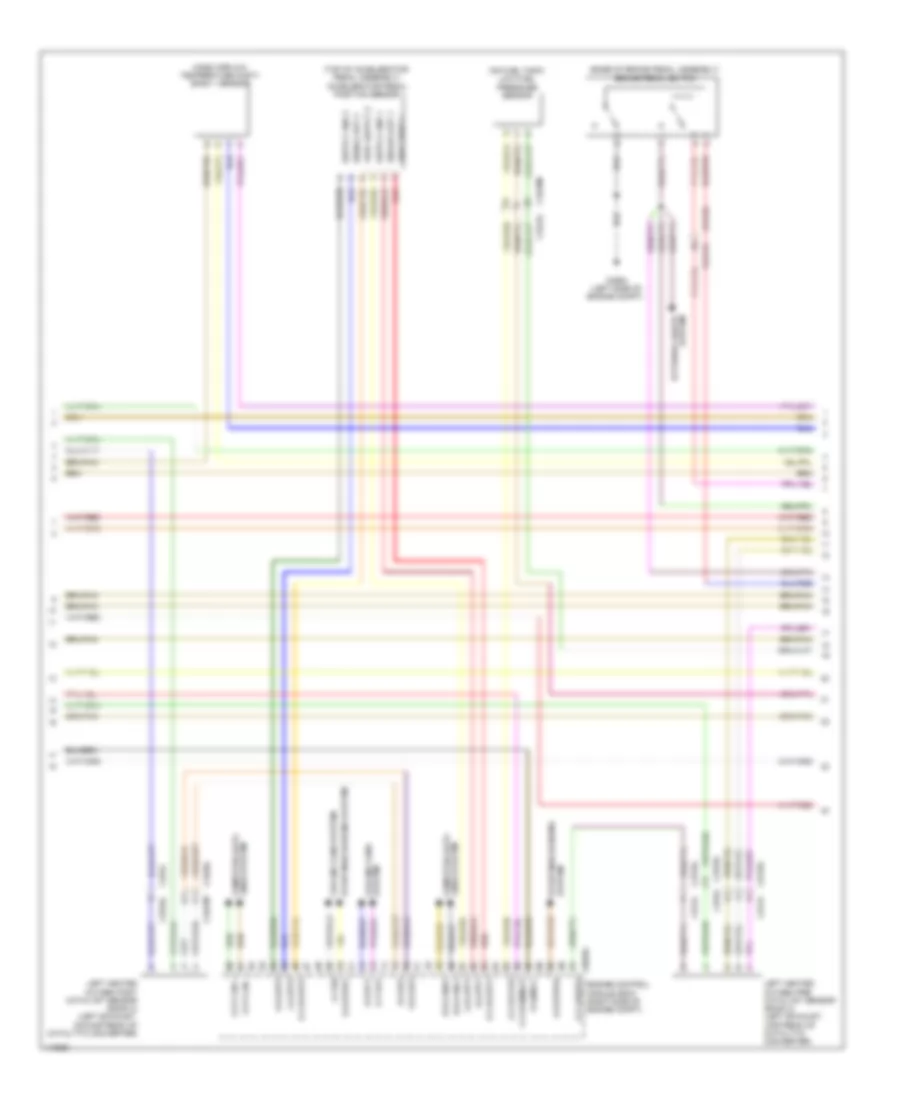
3.0L, Engine Performance Wiring Diagram (4 of 9) for Land Rover Discovery 4 HSE Lux 2014
List of elements for 3.0L, Engine Performance Wiring Diagram (4 of 9) for Land Rover Discovery 4 HSE Lux 2014:
- (rear of fuel rail assembly) fuel rail pressure sensor
- (rear of left cylinder bank) manifold absolute pressure & temperature (mapt) sensor
- (top center front of engine) manifold absolute pressure (map) sensor
- C0582
- C0585l
- C0634
- C2238l
- C2240l
- C2411l c2412l
- Central junction box (right side of dash)
- Engine control module (ecm) (right side of engine compt)
- Fuse 5a
- G-r-bps
- G-r-cbpp
- G-r-engts
- G-r-imps
- G-r-ocs
- Hot at all times
- Hot w/ ignition relay energized
- I-a-bps
- I-a-ks1b
- I-a-ks2b
- I-p-casea
- Ign coil 2
- Ign coil 5
- O t cbppos
- O-t-tvapos
- O-v-crs
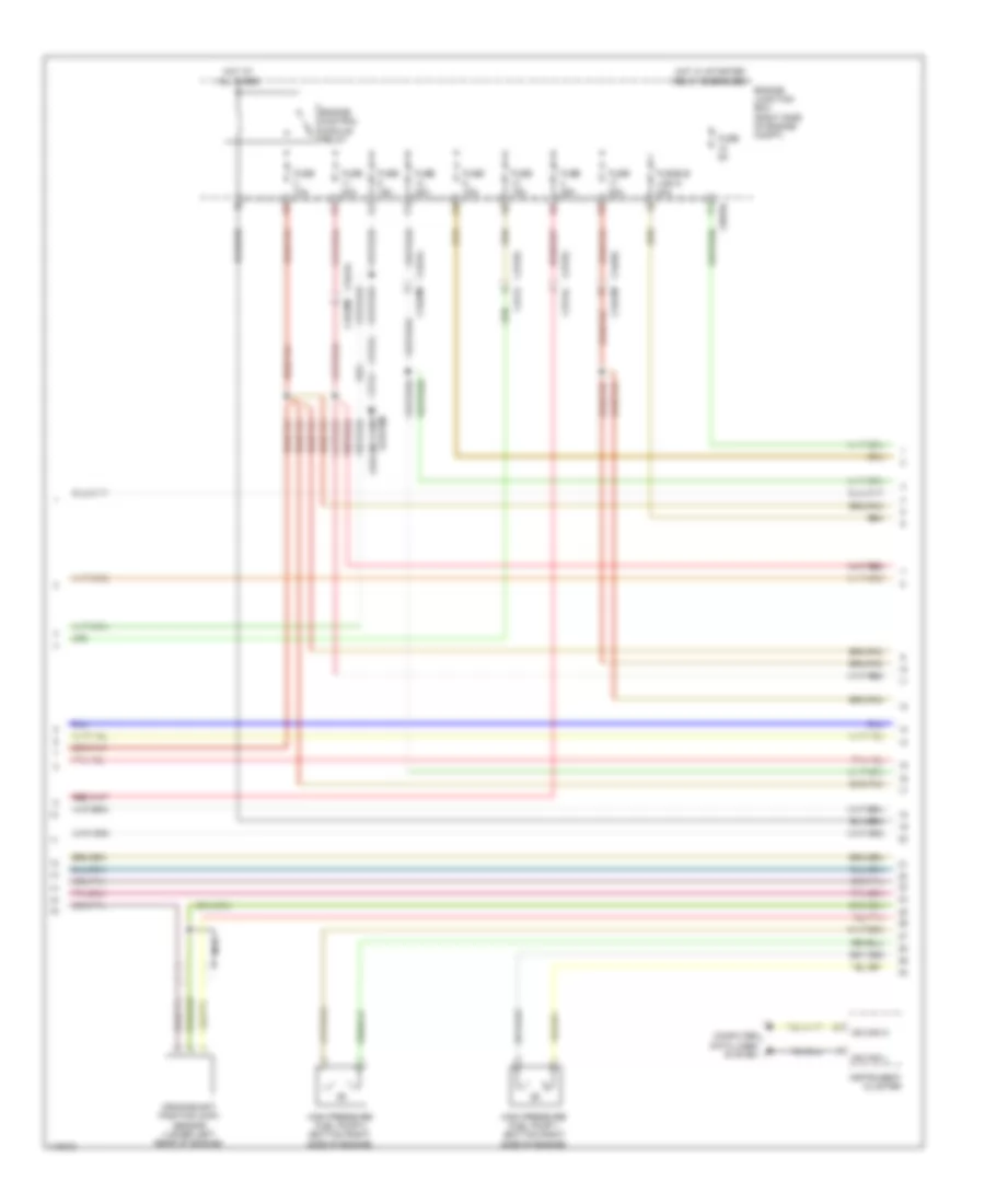
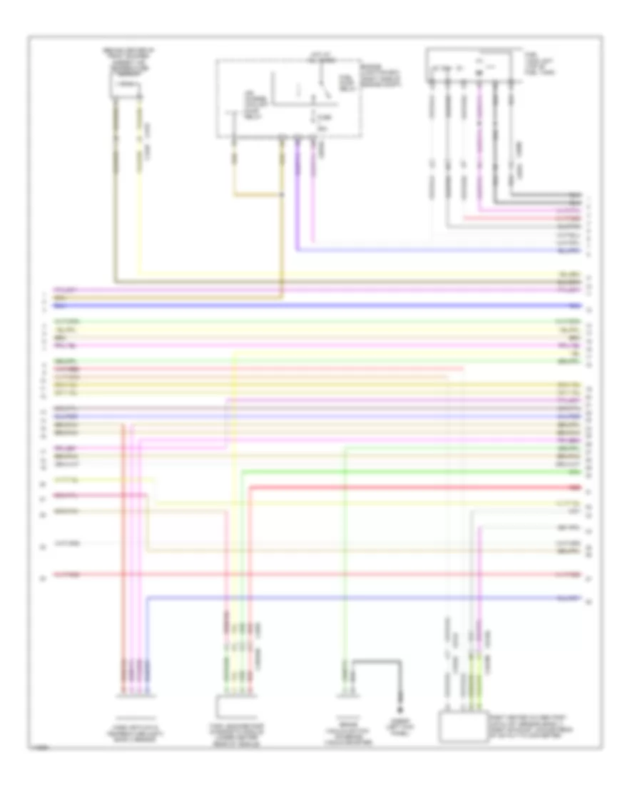
3.0L, Engine Performance Wiring Diagram (5 of 9) for Land Rover Discovery 4 HSE Lux 2014
List of elements for 3.0L, Engine Performance Wiring Diagram (5 of 9) for Land Rover Discovery 4 HSE Lux 2014:
- C0570l
- C2724
- C2724l
- C2725l
- C2725l c2724
- C3424l
- C3425m
- C3426l
- C3427m
- Computer data lines system
- Crankshaft position (ckp) sensor (lower left rear of engine)
- Engine control module relay
- Engine junction box (right side of engine compt)
- Fuse 10a
- Fuse 15a
- Fuse 20a
- Fuse 25a
- Fuse 5a
- Fusible link 5 40a
- High pressure fuel pump 1 (bottom right side of engine)
- High pressure fuel pump 2 (bottom right side of engine)
- Hot at all times
- Hot w/ starter relay energized
- Instrument cluster
- Ms can h
- Ms can l
- Nca
- System cooling fans
3.0L, Engine Performance Wiring Diagram (6 of 9) for Land Rover Discovery 4 HSE Lux 2014
List of elements for 3.0L, Engine Performance Wiring Diagram (6 of 9) for Land Rover Discovery 4 HSE Lux 2014:
- (top of left cylinder bank) fuel injector 6
- (top of right cylinder bank) fuel injector 2
- (under intake manifold, in left bank) left bank knock sensor
- (under intake manifold, in right bank) right bank knock sensor
- C0634
- C0904 c0909
- Engine control module (ecm) (right side of engine compt)
- G-r-crs
- Gnd
- I-a-cbpp
- I-a-ks1a
- I-a-ks2a
- I-a-railps
- I-f-crs
- Inj hs cyl 2a
- Inj hs cyl 3b
- Inj ls cyl 2a
- Inj ls cyl 3b
- Mtr +
- Mtr -
- O-p-fscvh1
- O-p-fscvh2
- O-p-fscvl1
- O-p-fscvl2
- O-v-5vcbpp
- Sig
- Supercharger bypass valve (top center front of engine)
- Tps 5v
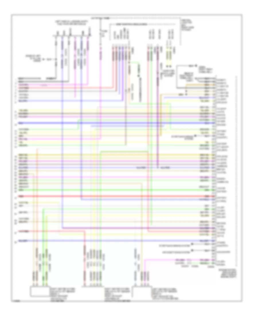
3.0L, Engine Performance Wiring Diagram (7 of 9) for Land Rover Discovery 4 HSE Lux 2014
List of elements for 3.0L, Engine Performance Wiring Diagram (7 of 9) for Land Rover Discovery 4 HSE Lux 2014:
- (base of brake pedal assembly) brake pedal switch
- (on fuel tank) low fuel pressure sensor
- (top of accelerator pedal assembly) accelerator pedal position sensor
- Analog out 1
- B-d-canh1
- B-d-canl1
- C0635l
- C2411l
- C2412l
- C2564 (left side of engine compt)
- C2724
- C2725l
- C2763l
- C2764
- C3424l
- C3425m
- C3426l
- C3427m
- Ccp can +
- Ccp can -
- Cooling fans system
- Engine control module (ecm) (right side of engine compt)
- G-r-app1
- G-r-app2
- G-r-lsf2
- I--a-app2
- I-a-app1
- I-a-lsf2
- I-f-fss
- Left heated oxygen post catalyst sensor (bank 2) (left exhaust, downstream of catalytic converter)
- Left heated oxygen pre catalyst sensor (bank 2) (left exhaust, upstream of catalytic converter)
- Lines system computer data
- Mass airflow temperature (maft) bank 1 sensor
- O-s-mrly
- O-s-pcf
- O-s-strph
- O-s-strpl
- O-t-evf
- O-t-lshup2
- O-v-5vapp1
- O-v-5vapp2
- O-v-5vflps
- Red
- Signal out 2
- Starting/charging system
- System cooling fans
- System exterior lights
- System starting/charging
- V-v-permbat
- Vref supp 1
3.0L, Engine Performance Wiring Diagram (8 of 9) for Land Rover Discovery 4 HSE Lux 2014
List of elements for 3.0L, Engine Performance Wiring Diagram (8 of 9) for Land Rover Discovery 4 HSE Lux 2014:
- (behind center of front bumper) ambient air temperature sensor
- Air charge coolant pump relay
- Brake vacuum switch (on brake vacuum booster)
- C0376
- C0390
- C0563p (left kick panel)
- C0570l
- C2293
- C2294sb
- C2763l
- C2764
- C3126
- C3127
- C3426l
- C3427m
- Engine junction box (right side of engine compt)
- Fuel pump relay
- Fuel tank unit (top of fuel tank)
- Fuse 25a
- Hot at all times
- Mass air flow & temperature (maft) bank 2 sensor
- Red
- Right heated oxygen post catalyst sensor (bank 1) (right exhaust, downstream of catalytic converter)
- Tank leakage pump diagnostic module (under center rear of vehicle)
3.0L, Engine Performance Wiring Diagram (9 of 9) for Land Rover Discovery 4 HSE Lux 2014
List of elements for 3.0L, Engine Performance Wiring Diagram (9 of 9) for Land Rover Discovery 4 HSE Lux 2014:
- (base of left "d" pillar) c2928s
- (left side of luggage compt) fuel pump driver module
- (rear of right front wheelwell) c3557l
- Active
- Air conditioning system
- Body control module (bcm)
- Brk diag
- Brk sw
- Brk sw 1
- C0580
- C0584l
- C0586l
- C0635l
- C2238l c2240l
- C2242l
- C2243l
- C2244l
- C2245l
- C2411l
- C2411l c2412l
- C2412l
- C2650l (right front wheelwell)
- C2724
- C2725l
- C2763l
- C2764
- C3424l
- C3425m
- C3426l
- C3427m
- Central junction box (right side of dash)
- Computer data lines system
- Diag
- Dnm
- Engine control module (ecm) (right side of engine compt)
- Fuel pump
- Fuse 5a
- G-g-bat1
- G-g-bat2
- G-g-bat3
- G-r-ams1
- G-r-ats
- G-r-df01
- G-r-isf4
- G-r-lsf1
- G-r-lsf3
- Gnd
- Gr fcps
- Hot at all times
- Hs can h
- Hs can l
- I t fpmd
- I-a-ats
- I-a-flps
- I-a-iats1
- I-a-iats2
- I-a-lscp1
- I-a-lscp2
- I-a-lsf1
- I-a-lsf3
- I-a-lsf4
- I-a-lsvn1
- I-a-lsvn2
- I-f-ams1
- I-f-ams2
- I-s-brkos
- I-s-brkvac
- I-s-t15
- I-s-t50
- I-s-t50r
- I-s-tnsw
- I-s-wak
- Left heated oxygen mid catalyst sensor (bank 2) (left exhaust mid catalytic converter)
- Motor +
- Motor -
- Nca
- O-r-lsvg1
- O-r-lsvg2
- O-s-cacwpr
- O-s-lsfh3
- O-s-strth
- O-s-strtl
- O-s-tdmh
- O-s-tdmp
- O-s-tdmv
- O-t-fpmc
- O-t-lshup1
- Passive
- Red
- Right heated oxygen mid catalyst sensor (bank 1) (right exhaust mid catalytic converter)
- Right heated oxygen pre catalyst sensor (bank 1) (right exhaust, upstream of catalytic converter)
- Starting/charging system
- Transmission system
- V-v-bat-1r
- V-v-bat-2r
- V-v-bat-3r

 Čeština
 Dansk
Dansk Deutsch
 Ελληνικά
 English
 Español
 Suomi
Suomi Français
 Français
 עברית
עברית Hrvatski
 Magyar
 Italiano
 日本語
日本語 한국어
한국어 Nederlands
 Polski
 Português
 Português
 Română
 Русский
 Slovenčina
 Slovenščina
 Svenska
 Türkçe
 中文 (中国)