ENGINE PERFORMANCE
3.0L
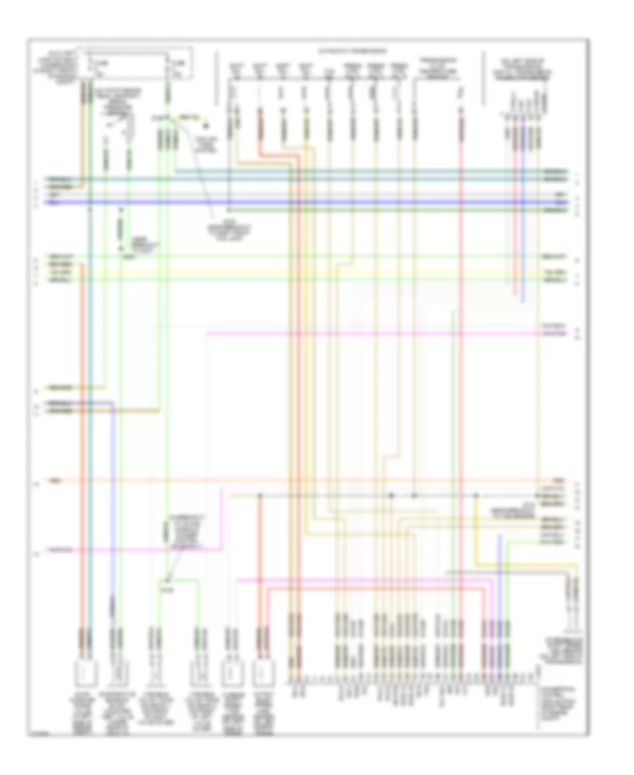
3.0L, Engine Performance Wiring Diagram (1 of 4) for Lincoln LS 2005
 https://portal-diagnostov.com/license.html
Automotive Electricians Portal FZCO
Automotive Electricians Portal FZCO
https://portal-diagnostov.com/license.html
https://portal-diagnostov.com/license.html
Automotive Electricians Portal FZCO
Automotive Electricians Portal FZCO
List of elements for 3.0L, Engine Performance Wiring Diagram (1 of 4) for Lincoln LS 2005:
- (in body main harness, near breakout to c291)
- (in breakout to battery junction box) s403
- (near breakout to ambient air temperature sensor)
- (near breakout to right front wheel speed
- (near breakout to right front wheel speed sensor)
- (near breakout to underhood auxiliary junction box)
- (on right front fender) g102
- (on right radiator support) g101
- 15s-re21
- 15s-re25
- 15s-re8
- 29-re8
- 29s-re13
- 31-re21
- 31-re25
- 31-re26
- 31-re8
- 31s-pg24
- 4-ec7
- 4-re8
- 5-ec7
- 5-re8
- 7-pg24
- 7-re14
- 7-re8
- 7-rj30
- 7-rj35
- 8-fa88
- 8-pa47
- 8-re32
- 8-rj10
- 8-rj13
- 8-rj17
- 8-rj22
- 8-rj30
- 8-rj35
- 8-rj36
- 8-ta21
- 8-ta67
- 8-ta68
- 9-re8
- 9-rj22
- 9-rj30
- 91-re27
- 91s-fa79
- 91s-rl25
- 91s-rl3
- A/c pressure transducer sensor (in left front of engine compt)
- Ac clutch
- Ac press
- Air conditioning system
- Auxiliary junction box (underhood) (in right front of engine compt)
- Battery junction box (bjb) (in luggage compt, near battery)
- Brake in
- C175b
- C270b
- C270c
- C270d
- Can +
- Can -
- Central junction box (cjb) (behind right kick panel)
- Cooling fans system
- Cops & heated oxygen sensor relay
- Cruise control system
- Data link connector (under left side of dash)
- Electronic throttle control module (behind left side of dash)
- Etc ref
- Etc sig
- Etc sig rtn
- Etc signal
- Evap ctrl
- Evap purge
- Fan ctrl
- Fuel pump motor diode
- Fuel tank pressure transducer sensor (under rear of vehicle)
- Fuse 30a
- Fuse 5a
- G102 (on right front fender)
- Ground
- Hot at all times
- Hot in run
- Hot in run or start
- Iat sens
- Inertia fuel shut-off (ifs) switch (inside left kick panel)
- Maf rtn
- Maf sig
- Man mode (+)
- Man mode (-)
- Mass air flow (maf) sensor (on air intake assembly)
- Mt sw +
- Mt sw -
- O/d cancel sw
- Od off
- Pcm power diode
- Pcm power relay
- Power
- Powertrain control module (pcm) (right rear of engine compt)
- Prg sig
- Red
- Ref volt
- Rem sig
- Rest mod
- S102
- S103
- S111
- S112
- S113
- S138 (near breakout to underhood auxiliary junction box)
- S211
- S220
- S328 (near breakout to yaw velocity sensor)
- Scp +
- Scp -
- Sensor)
- Signal rtn
- Spd sw
- Tank press
- Transmission shift selector (a/t) (on center of floor pan)
- Voltage
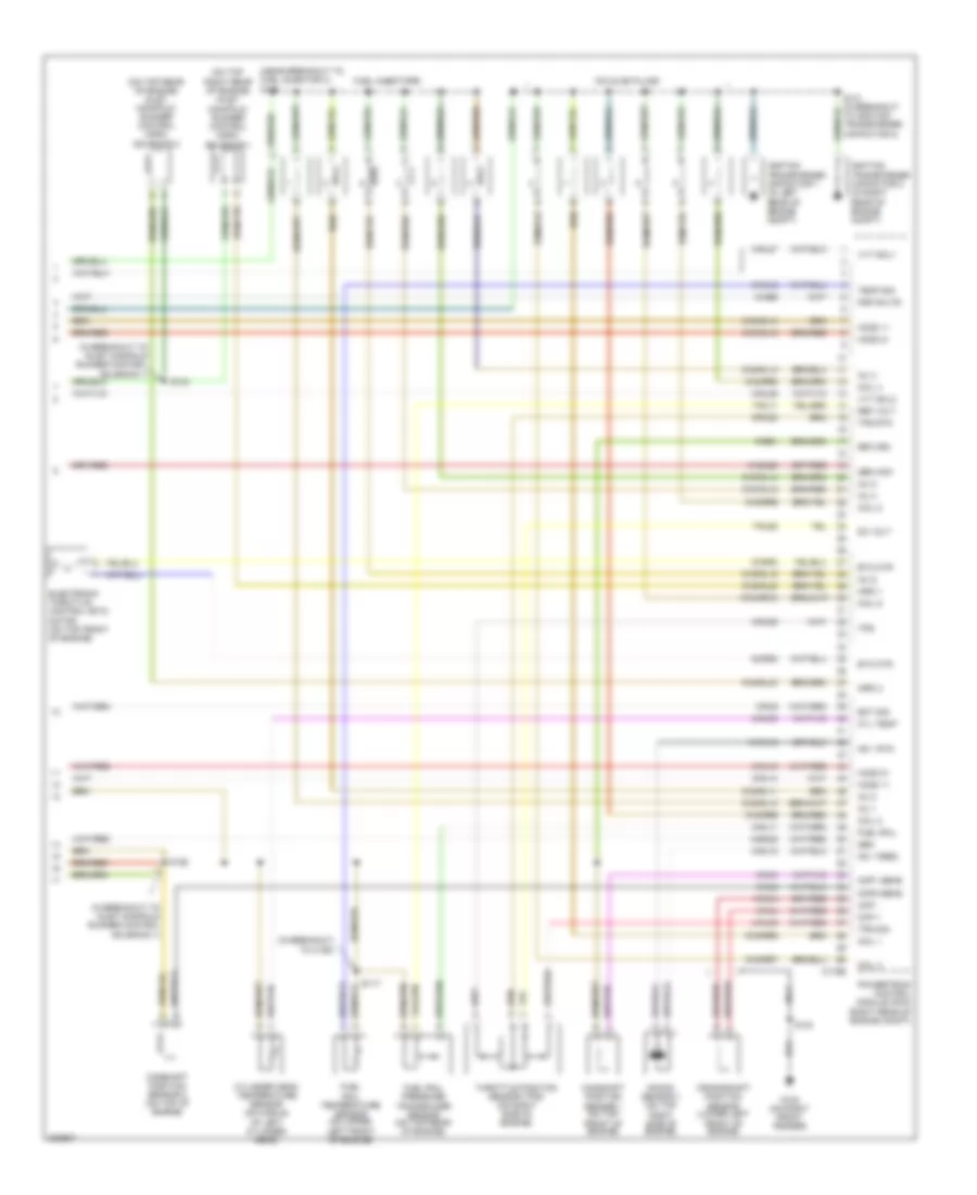
3.0L, Engine Performance Wiring Diagram (2 of 4) for Lincoln LS 2005
List of elements for 3.0L, Engine Performance Wiring Diagram (2 of 4) for Lincoln LS 2005:
- (in breakout to intake manifold runner control solenoid 1)
- (near breakout to c237)
- (on left side of transmission) digital transmission range (dtr) sensor
- (on top of brake pedal support) brake pressure switch
- 8-rj25
- 8-rj26
- 8-ta26
- 8-ta27
- 8-ta37
- 8-ta38
- 8-ta39
- 8-ta40
- 8-ta51
- 8-ta74
- 9-ta1
- 91s-rj25
- 91s-rj26
- 91s-ta23
- 91s-ta24
- 91s-ta47
- 91s-ta63
- 91s-ta64
- 91s-ta65
- 91s-ta69
- 91s-ta70
- Automatic transmission
- Auxiliary junction box (underhood) (in right front of engine compt)
- C175t
- Cooling fans system
- Evap canister purge valve (in left side of engine compt)
- Evaporative emission (evap) canister vent valve (under rear of vehicle)
- Fuse 15a
- Ho2s 12
- Ho2s 22
- Intermediate shaft speed (iss) sensor (on left side of transmission)
- Iss
- Oss
- Output shaft speed (oss) sensor (on left side of trans)
- P,3/4,2,1
- P,n,1
- P,r,2
- P,r,n,3/4
- Pcs a
- Pcs b
- Pcs c
- Power
- Powertrain control module (pcm) (right rear of engine compt)
- Press ctrl sol a
- Press ctrl sol b
- Press ctrl sol c
- S104
- S105 (near breakout to right front fog lamp)
- S110 (near breakout to tss sensor)
- S125
- S204
- Shift sol a
- Shift sol b
- Shift sol c
- Shift sol d
- Sig rtn
- Ss a
- Ss b
- Ss c
- Ss d
- Tcc sol
- Tft
- Tr1
- Tr2
- Tr3a
- Tr4
- Transmission fluid temperature sensor
- Tss
- Turbine shaft speed (tss) sensor (on left side of trans)
- Variable valve timing solenoid 1 (on front of right valve cover)
- Variable valve timing solenoid 2 (on front of left valve cover)
3.0L, Engine Performance Wiring Diagram (3 of 4) for Lincoln LS 2005
List of elements for 3.0L, Engine Performance Wiring Diagram (3 of 4) for Lincoln LS 2005:
- "c" pillar)
- (in breakout to c432)
- (in breakout to luggage compt lamp) s434
- (in breakout to rear electronic module)
- (in right side of luggage compt) rear electronic module (rem)
- (near breakout heated oxygen sensor 12)
- (near breakout to fuel tank pressure transducer sensor)
- (near breakout to imrc solenoid 2)
- (near breakout to right front fog lamp) s106
- (near breakout to right front wheel speed sensor)
- (near breakout to underhood auxiliary junction box)
- (right front side of engine compt) (w/ stability) abs control module
- (under left side of dash) auxiliary junction box (interior)
- 15-rp12b
- 15s-dk32
- 15s-rg2a
- 29s-cf1
- 29s-cf2
- 29s-cf58
- 29s-dk30
- 31s-rg2a
- 4-eg12
- 5-eg12
- 8-ga25
- 8-ga7
- 8-re32
- 9-ga1
- Abs control module (w/o stability) (right front side of engine compt)
- Air conditioning system
- Auxiliary junction box (underhood) (in right front of engine compt)
- Battery junction box (bjb) (in luggage compt, near battery)
- Brake pedal position switch (on top of brake pedal support)
- C102a
- C220b
- C270d
- C283b
- C283c
- C283d
- C420a
- C420b
- C420c
- C420d
- Central junction box (cjb) (behind right kick panel)
- Data link connector (dlc) (under left side of dash)
- Engine oil temperature sensor (on left front side of engine)
- Fuel pump relay
- Fuel sender (at left side of luggage compt)
- Fuel tank unit (at left side of luggage compt)
- Fuse 15a
- Fuse 5a
- G300 (at right
- G401 (at right rear of luggage compt)
- Generator
- Heated oxygen sensor (ho2s) 11 (lower right rear of engine, in exhaust manifold)
- Heated oxygen sensor (ho2s) 12 (in exhaust, rear of catalyst)
- Heated oxygen sensor (ho2s) 21 (lower left rear of engine, in exhaust manifold)
- Heated oxygen sensor (ho2s) 22 (in exhaust, rear of catalyst)
- Hot at all times
- Instrument cluster
- J/c 4 (behind left side of dash)
- Nca
- Power steering pressure switch (in left side of engine compt)
- S101
- S109
- S132
- S135
- S402
- S435
- S436 (in breakout to luggage compt lamp)
- S437
- S438
- S439
- W/ stability
- W/o stability
3.0L, Engine Performance Wiring Diagram (4 of 4) for Lincoln LS 2005
List of elements for 3.0L, Engine Performance Wiring Diagram (4 of 4) for Lincoln LS 2005:
- (in breakout to c192)
- (in breakout to inlet manifold runner control solenoid 1)
- (near breakout to fuel injector 3) s128
- (on top rear of engine) inlet manifold runner control (imrc) solenoid 2
- (on top right rear of engine) inlet manifold runner control (imrc) solenoid 1
- 10-ba25
- 10-rj18
- 10-rj4
- 32-rg3
- 33-rg3
- 7-rj11
- 7-rj28
- 8-ba25
- 8-ce6
- 8-rj11
- 8-rj12
- 8-rj14
- 8-rj15
- 8-rj18
- 8-rj2
- 8-rj28
- 8-rj3
- 8-rj33
- 8-rj39
- 8-rj4
- 8-rj6
- 8-rl26
- 8-rl27
- 9-re1
- 9-rj28
- 91s-rj14
- 91s-rj15
- 91s-rl10
- 91s-rl11
- 91s-rl12
- 91s-rl13
- 91s-rl14
- 91s-rl15
- 91s-rl20
- 91s-rl40
- 91s-rr10
- 91s-rr5
- 91s-rr6
- 91s-rr7
- 91s-rr8
- 91s-rr9
- C175e
- Camshaft position sensor 1 (on top front of engine)
- Camshaft position sensor 2 (on top of engine)
- Ckp +
- Ckp -
- Cmp1 sens
- Cmp2 sens
- Coil 1
- Coil 2
- Coil 3
- Coil 4
- Coil 5
- Coil 6
- Coils on plugs
- Crankshaft position sensor (lower left front of engine)
- Cyl temp
- Cylinder head temperature sensor (on middle of left cylinder head)
- Dc volt
- Electronic throttle control (etc) motor (on top front of engine)
- Eot sig
- Etc mtr
- Fuel injectors
- Fuel rail
- Fuel rail pressure transducer sensor (on top rear of engine)
- Fuel rail temperature sensor (on upper left front of engine)
- G102 (on right front fender)
- Gen
- Gen com
- Ho2s 11
- Ho2s 21
- Ignition transformer capacitor 1 (in left rear of engine compt)
- Ignition transformer capacitor 2 (in right rear of engine compt)
- Imrc 1
- Imrc 2
- Inj 1
- Inj 2
- Inj 3
- Inj 4
- Inj 5
- Inj 6
- Knock sensor 1 (on top right side of engine)
- Ks 1 feed
- Ks 1 rtn
- Nca
- Powertrain control module (pcm) (right rear of engine compt)
- Psp sw fd
- Ref volt
- Return
- S117
- S124
- S126
- S131 (in breakout to ignition transformer capacitor 2)
- S134
- Temp sig
- Throttle position sensor (tps) (on right side of engine)
- Tps
- Tps rtn
- Tps sig
- Vvt sol1
- Vvt sol2
3.9L
3.9L, Engine Performance Wiring Diagram (1 of 4) for Lincoln LS 2005
List of elements for 3.9L, Engine Performance Wiring Diagram (1 of 4) for Lincoln LS 2005:
- (in body main harness, near breakout to c291)
- (in breakout to battery junction box) s403
- (near breakout to ambient air temperature sensor)
- (near breakout to right front wheel speed
- (near breakout to right front wheel speed sensor)
- (near breakout to underhood auxiliary junction box)
- (on right front fender)
- (on right front fender) g102
- (on right radiator support)
- 15s-re21
- 15s-re25
- 15s-re8
- 29-re8
- 29s-re13
- 31-re21
- 31-re25
- 31-re26
- 31-re8
- 31s-pg24
- 4-ec7
- 4-re8
- 5-ec7
- 5-re8
- 7-pg24
- 7-re14
- 7-re8
- 7-rj30
- 7-rj35
- 8-fa88
- 8-pa47
- 8-re32
- 8-rj10
- 8-rj13
- 8-rj17
- 8-rj22
- 8-rj30
- 8-rj35
- 8-rj36
- 8-ta21
- 8-ta67
- 8-ta68
- 9-re8
- 9-rj22
- 9-rj30
- 91-re27
- 91s-fa79
- 91s-rl25
- 91s-rl3
- A/c pressure transducer sensor (on left front of engine compt)
- Ac clutch
- Ac press
- Air conditioning system
- Auxiliary junction box (underhood) (in right front of engine compt)
- Battery junction box (in luggage compt, near battery)
- Brake in
- C175b
- C270b
- C270c
- C270d
- Can +
- Can -
- Central junction box (cjb) (behind right kick panel)
- Cooling fans system
- Cops & heated oxygen sensor relay
- Cruise control system
- Data link connector (under left side of dash)
- Electronic throttle control module (behind left side of dash)
- Etc ref
- Etc sig
- Etc sig rtn
- Etc signal
- Evap ctrl
- Evap purge
- Fan ctrl
- Fuel pump motor diode
- Fuel tank pressure transducer sensor (under rear of vehicle)
- Fuse 30a
- Fuse 5a
- G101
- G102
- Ground
- Hot at all times
- Hot in run
- Hot in run or start
- Iat sens
- Inertia fuel shut-off (ifs) switch (inside left kick panel)
- Maf rtn
- Maf sig
- Man mode (+)
- Man mode (-)
- Mass air flow (maf) sensor (on air intake assembly)
- Mt sw +
- Mt sw -
- O/d cancel sw
- Od off
- Pcm power diode
- Pcm power relay
- Power
- Powertrain control module (pcm) (right rear of engine compt)
- Prg sig
- Red
- Ref volt
- Rem sig
- Rest mod
- S102
- S103
- S111
- S112
- S113
- S138 (near breakout to underhood auxiliary junction box)
- S211
- S220
- S328 (near breakout to yaw velocity sensor)
- Scp +
- Scp -
- Sensor)
- Signal rtn
- Spd sw
- Tank press
- Transmission shift selector (a/t) (on center of floor pan)
- Voltage
3.9L, Engine Performance Wiring Diagram (2 of 4) for Lincoln LS 2005
List of elements for 3.9L, Engine Performance Wiring Diagram (2 of 4) for Lincoln LS 2005:
- (in breakout to intake manifold runner control solenoid 1)
- (near breakout to c237)
- (near breakout to turbine shaft speed sensor)
- (on left side of transmission) digital transmission range (dtr) sensor
- (top of brake pedal support) brake pressure switch
- 8-rj25
- 8-rj26
- 8-ta26
- 8-ta27
- 8-ta37
- 8-ta38
- 8-ta39
- 8-ta40
- 8-ta51
- 8-ta74
- 9-ta1
- 91s-rj25
- 91s-rj26
- 91s-ta23
- 91s-ta24
- 91s-ta47
- 91s-ta63
- 91s-ta64
- 91s-ta65
- 91s-ta69
- 91s-ta70
- Automatic transmission
- Auxiliary junction box (underhood) (right front of engine compt)
- C175t
- Cooling fans system
- Evap canister purge valve (left side of engine compt)
- Evaporative emission (evap) canister vent valve (under rear of vehicle)
- Fuse 15a
- Ho2s 12
- Ho2s 22
- Intermediate shaft speed (iss) sensor (on left side of trans)
- Iss
- Oss
- Output shaft speed sensor (left side of trans)
- P,3/4,2,1
- P,n,1
- P,r,2
- P,r,n,3/4
- Pcs a
- Pcs b
- Pcs c
- Power
- Powertrain control module (pcm) (right rear of engine compt)
- Press ctrl sol a
- Press ctrl sol b
- Press ctrl sol c
- S104
- S105 (near breakout to right front fog lamp)
- S110
- S125
- S204
- Shift sol a
- Shift sol b
- Shift sol c
- Shift sol d
- Sig rtn
- Ss a
- Ss b
- Ss c
- Ss d
- Tcc sol
- Tft
- Tr1
- Tr2
- Tr3a
- Tr4
- Transmission fluid temperature sensor
- Tss
- Turbine shaft speed (tss) sensor (left side of trans)
- Variable valve timing solenoid 1 (on front of right valve cover)
- Variable valve timing solenoid 2 (on front of left valve cover)
3.9L, Engine Performance Wiring Diagram (3 of 4) for Lincoln LS 2005
List of elements for 3.9L, Engine Performance Wiring Diagram (3 of 4) for Lincoln LS 2005:
- "c" pillar)
- (in breakout to c432)
- (in breakout to luggage compt lamp) s434
- (in breakout to rear electronic module)
- (in engine control sensor & fuel charge harness, in breakout to c140)
- (in right side of luggage compt) rear electronic module (rem)
- (near breakout to fuel tank pressure transducer sensor)
- (near breakout to heated oxygen sensor
- (near breakout to right front fog lamp) s106
- (near breakout to right front wheel speed
- (right front side of engine compt) (w/ stability) abs control module
- (under left side of dash) auxiliary junction box (interior)
- 12)
- 15-rp12b
- 15s-dk32
- 15s-rg2a
- 29s-cf1
- 29s-cf2
- 29s-dk30
- 31s-rg2a
- 4-eg12
- 5-eg12
- 8-ga25
- 8-ga7
- 8-re32
- 9-ga1
- Abs control module (w/o stability) (right front side of engine compt)
- Air conditioning system
- Auxiliary junction box (underhood) (in right front of engine compt)
- Battery junction box (bjb) (in luggage compt, near battery)
- C220b
- C251
- C283b
- C283c
- C283d
- C420a
- C420b
- C420c
- C420d
- Camshaft position sensor 2 (top left rear of engine)
- Data link connector (dlc) (under left side of dash)
- Engine oil temperature sensor (on lower front of engine)
- Fuel pump relay
- Fuel rail temperature sensor (top right rear of engine)
- Fuel sender (left side of luggage compt)
- Fuel tank unit (left side of luggage compt)
- Fuse 15a
- G300 (right
- G401 (at right rear of luggage compt)
- Generator
- Heated oxygen sensor (ho2s) 11 (right exhaust manifold)
- Heated oxygen sensor (ho2s) 12 (in exhaust, rear of catalyst)
- Heated oxygen sensor (ho2s) 21 (left exhaust manifold)
- Heated oxygen sensor (ho2s) 22 (in exhaust, rear of catalyst)
- Hot at all times
- Instrument cluster
- J/c 4 (behind left side of dash)
- Nca
- Power steering pressure switch (left side of engine compt)
- S101
- S109
- S132
- S135 (near breakout to underhood auxiliary junction box)
- S402
- S435
- S436 (in breakout to luggage compt lamp)
- S437
- S438
- S439
- Sensor)
- W/ stability
- W/o stability
3.9L, Engine Performance Wiring Diagram (4 of 4) for Lincoln LS 2005
List of elements for 3.9L, Engine Performance Wiring Diagram (4 of 4) for Lincoln LS 2005:
- (in breakout to coil on plug 8) s129
- (in breakout to fuel injector 8) s130
- (in breakout to ignition transformer
- 10-ba25
- 10-rj18
- 10-rj19
- 10-rj4
- 32-rg3
- 33-rg3
- 7-rj28
- 7-rn11
- 8-ba25
- 8-ce6
- 8-rj11
- 8-rj12
- 8-rj14
- 8-rj15
- 8-rj18
- 8-rj19
- 8-rj2
- 8-rj20
- 8-rj28
- 8-rj3
- 8-rj33
- 8-rj39
- 8-rj4
- 8-rj6
- 8-rj7
- 8-rl26
- 8-rl27
- 9-re1
- 9-rj28
- 91s-rj14
- 91s-rj15
- 91s-rl10
- 91s-rl11
- 91s-rl12
- 91s-rl13
- 91s-rl14
- 91s-rl15
- 91s-rl16
- 91s-rl17
- 91s-rl7
- 91s-rr10
- 91s-rr11
- 91s-rr12
- 91s-rr5
- 91s-rr6
- 91s-rr7
- 91s-rr8
- 91s-rr9
- Brake pedal position switch (on top of brake pedal support)
- C175e
- C270d
- Camshaft position sensor 1 (right rear of cylinder head)
- Capacitor 1)
- Central junction box (cjb) (behind right kick panel)
- Ckp +
- Ckp -
- Cmp1 sens
- Cmp2 sens
- Coil 1
- Coil 2
- Coil 3
- Coil 4
- Coil 5
- Coil 6
- Coil 7
- Coil 8
- Coils on plugs
- Crankshaft position sensor (lower left side of engine)
- Cyl temp
- Cylinder head temperature sensor (left cylinder head)
- Dc volt
- Egr system module (upper right front of engine)
- Electronic throttle control motor (on top front of engine)
- Eot sig
- Ept ctrl
- Ept sens
- Ept sig
- Etc mtr
- Fuel injectors
- Fuel rail
- Fuel rail pressure transducer sensor (top right side of engine)
- Fuse 5a
- G102 (right front fender)
- Gen
- Gen com
- Ho2s 11
- Ho2s 21
- Hot at all times
- Ignition trans- former capacitor 1 (left rear engine compt)
- Ignition trans- former capacitor 2 (right rear engine compt)
- Inj 1
- Inj 2
- Inj 3
- Inj 4
- Inj 5
- Inj 6
- Inj 7
- Inj 8
- Knock sensor 1 (top right side of engine)
- Knock sensor 2 (top left side of engine)
- Ks 1 feed
- Ks 1 rtn
- Ks 2 feed
- Ks 2 rtn
- Nca
- Powertrain control module (pcm) (right rear of engine compt)
- Psp sw fd
- Ref volt
- Return
- S124
- S126
- S127
- S131 (in breakout to coil on plug 3)
- S150 (near breakout to cmp 1)
- Temp sig
- Throttle position sensor (top front of engine)
- Tps
- Tps rtn
- Tps sig
- Vvt sol1
- Vvt sol2

 Čeština
 Dansk
Dansk Deutsch
 Ελληνικά
 English
 Español
 Suomi
Suomi Français
 Français
 עברית
עברית Hrvatski
 Magyar
 Italiano
 日本語
日本語 한국어
한국어 Nederlands
 Polski
 Português
 Português
 Română
 Русский
 Slovenčina
 Slovenščina
 Svenska
 Türkçe
 中文 (中国)