ENGINE PERFORMANCE
4.6L
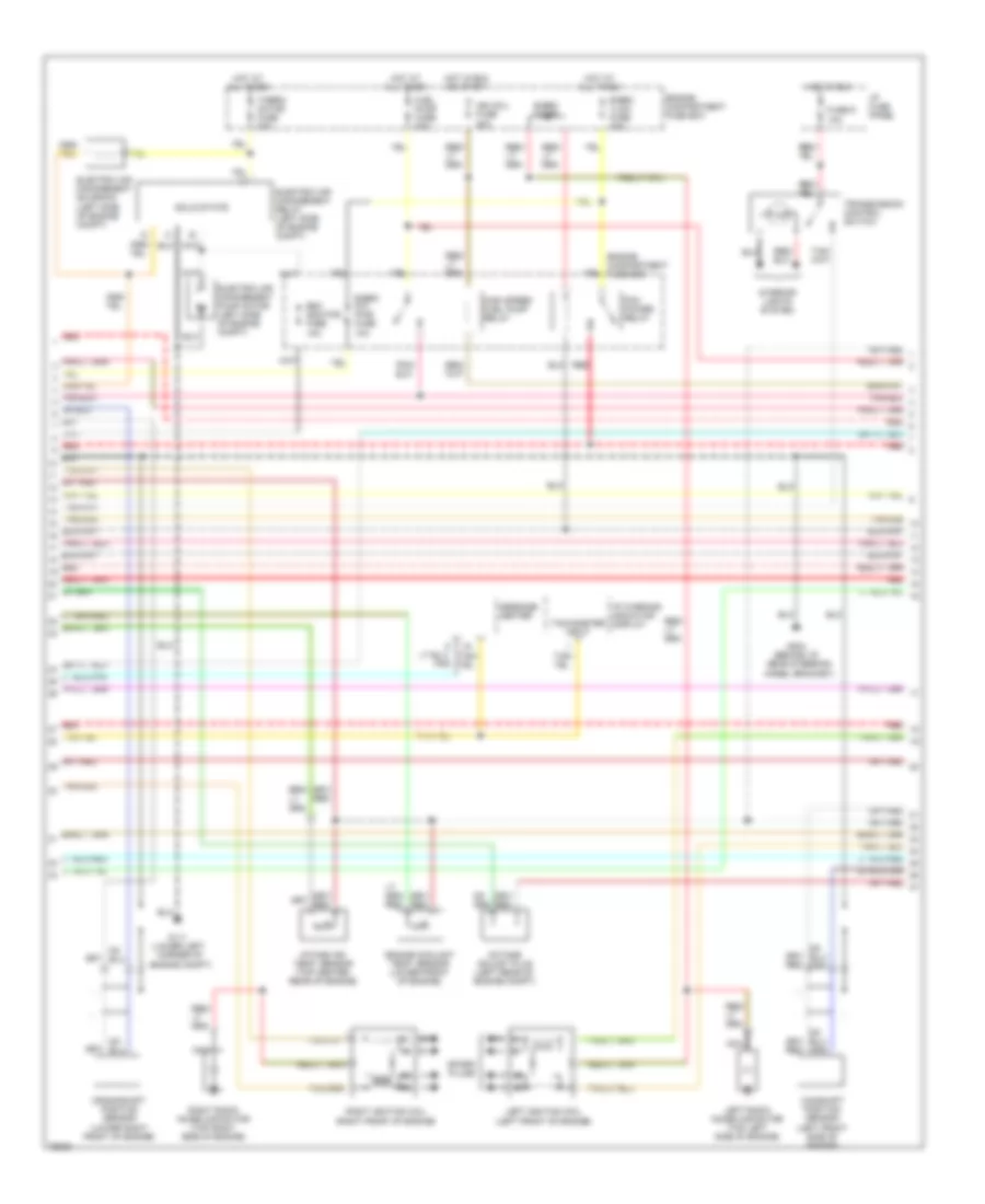
4.6L, Engine Performance Wiring Diagrams (1 of 3) for Lincoln Mark VIII LSC 1996
 https://portal-diagnostov.com/license.html
Automotive Electricians Portal FZCO
Automotive Electricians Portal FZCO
https://portal-diagnostov.com/license.html
https://portal-diagnostov.com/license.html
Automotive Electricians Portal FZCO
Automotive Electricians Portal FZCO
List of elements for 4.6L, Engine Performance Wiring Diagrams (1 of 3) for Lincoln Mark VIII LSC 1996:
- (left front floor pan)
- 4r70w transmission
- A/c cycling switch
- Data link connector (top of left
- Egr vacuum regulator solenoid (left rear of engine compt)
- Electronic pressure control solenoid
- Evaporative emission canister purge solenoid (right front of engine compt, top vapor canister)
- Front wheelwell)
- Fuel pump module (top of fuel tank)
- G108 (left front of engine compt)
- G200
- G203 (right front floor pan)
- G206 (center i/p, left of radio)
- Inertia fuel shut-off switch (left rear side of trunk)
- Intake manifold runner control monitors (top center rear of engine)
- Intake manifold runner control solenoid (top center rear of engine)
- Left knock sensor (left rear of engine compt)
- Mass air flow sensor (right front of engine compt)
- Nca
- Powertrain control module (behind i/p, left side of safety wall)
- Red
- Right knock sensor (left rear of engine compt)
- Shift solenoid
- Torque converter clutch solenoid
- Trans. fluid temp. sensor
- Vehicle speed sensor (left rear of transmission)
4.6L, Engine Performance Wiring Diagrams (2 of 3) for Lincoln Mark VIII LSC 1996
List of elements for 4.6L, Engine Performance Wiring Diagrams (2 of 3) for Lincoln Mark VIII LSC 1996:
- Camshaft position sensor (left front side of engine)
- Crankshaft position sensor (lower right front of engine)
- E-eec diode
- E-eec k/a pwr fuse 10a
- E-eec vlcm fuse 30a
- Eam monitor fuse 10a
- Electric air management pump motor (left side of engine compt)
- Electric air management relay (left side of engine compt)
- Electric air management solenoid (left side of engine compt)
- Engine compartment fuse box
- Engine coolant temp. sensor (lower front of engine)
- Fuel pump fuse 20a
- Fuse 9 10a
- G111 (lower left corner of engine compt)
- G204 (behind i/p, near steering wheel bracket)
- High speed fuel pump relay
- Hot at all times
- Hot in run
- Hot in run or start
- I/p fuse panel
- I/p warning indicator display
- Ign coil fuse 20a
- Intake air temp. sensor (top center rear of engine)
- Interior lights system
- Left ignition coil (left front of engine)
- Left radio noise capacitor (top left side of engine)
- Message center
- Nca
- Octane adjust plug (left rear of engine compt)
- Pcm power relay
- Pnk
- Red
- Right ignition coil (right front of engine)
- Right radio noise capacitor (top right side of engine)
- Solid state
- Spark plugs
- Tachometer input
- Therm- actor fuse 30a
- Transmission control switch
4.6L, Engine Performance Wiring Diagrams (3 of 3) for Lincoln Mark VIII LSC 1996
List of elements for 4.6L, Engine Performance Wiring Diagrams (3 of 3) for Lincoln Mark VIII LSC 1996:
- (on brake pedal support)
- A/c clutch coil
- A/c refrigerant pressure sensor (right front of engine compt)
- Brake on/off switch
- Cool fan fuse 40a
- Differential pressure feed- back egr sensor (left rear of engine)
- Electric cooling fan
- Engine compartment fuse box
- Fuel injectors
- Fuse 11 15a
- G101 (right front fender apron)
- Hot at all times
- Hot in run or start
- I/p fuse panel
- I/p warning indicator display
- Idle air control valve (center rear of engine)
- Left front heated oxygen sensor #21 (in exhaust manifold)
- Left rear heated oxygen sensor #12 (rear of catalytic converter)
- Malfunction indicator lamp (mil) (check engine)
- N r
- Nca
- Output shaft speed sensor (left side of transmission)
- Powertrain control module (behind i/p, left side of safety wall)
- Red
- Right front heated oxygen sensor #11 (in exhaust manifold)
- Right rear heated oxygen sensor #22 (rear of catalytic converter)
- Tan
- Tan/red
- Throttle position sensor (top center rear of engine)
- Transmission control indicator (o/d off)
- Transmission range sensor (left side of transmission)
- Variable load control module (lower front center of engine compt)

 Čeština
 Dansk
Dansk Deutsch
 Ελληνικά
 English
 Español
 Suomi
Suomi Français
 Français
 עברית
עברית Hrvatski
 Magyar
 Italiano
 日本語
日本語 한국어
한국어 Nederlands
 Polski
 Português
 Português
 Română
 Русский
 Slovenčina
 Slovenščina
 Svenska
 Türkçe
 中文 (中国)