ENGINE PERFORMANCE
Engine Performance Wiring Diagram (1 of 5) for Lincoln Navigator 2006
 https://portal-diagnostov.com/license.html
Automotive Electricians Portal FZCO
Automotive Electricians Portal FZCO
https://portal-diagnostov.com/license.html
https://portal-diagnostov.com/license.html
Automotive Electricians Portal FZCO
Automotive Electricians Portal FZCO
List of elements for Engine Performance Wiring Diagram (1 of 5) for Lincoln Navigator 2006:
- (in engine control sensor harness, near breakout to g102) s109
- 4wd sw pos sns
- 4wd sw sig rtn
- A/c clu rly ctrl
- Air bag sig
- Air conditioning system
- Air suspension module (under left side of dash)
- Alternator
- Alternator monitor
- Anti-theft ind
- Anti-theft system
- App sensor power
- App sensor return
- App sensor sig 1
- App sensor sig 2
- App sensor sig 3
- Bpp sw signal
- C175b
- C2131a
- C240a
- C270a
- C270b
- C270d
- C270f
- C270g
- C270k
- C4014b
- Canister vent
- Central junction box (cjb) (behind right kick panel)
- Cruise control system
- Deactivator sw sig
- Exterior lights system
- Fpm monitor
- Fuel pump ctrl
- Fuel pump relay
- Fuel tank sensor
- Fuse
- Fuse 15a
- Fuse 25a
- Fuse 7.5a
- G101 (near right side of radiator)
- G102 (on right rear of engine compartment)
- G102 (on right rear of engine compt)
- Ground
- Heated positive crankcase ventilation (pcv) valve relay
- High speed can +
- High speed can -
- Hot at all times
- Hot in run or start
- Iat sensor sig
- Inertia fuel shut-off switch (at left rear corner of cargo area, behind trim)
- Kick panel) g200
- Maf sensor sig
- Maf sns sig rtn
- Mass air flow/intake air temperature (maf/iat) sensor (in intake system)
- Module program
- Parking aid module (pam) (at left side of cargo area, behind trim)
- Pcm power diode
- Pcm power relay
- Powertrain control module (pcm) (on right side of firewall)
- Pressure switch
- Radio
- Red
- Red/pnk
- Reference volt
- Rx signal
- S107 (in engine control sensor harness, near breakout to g102)
- S108
- S116
- S133
- S152 (w/ four wheel drive)
- S153
- S203
- Sig return
- Solenoid ctrl
- Speed ctrl sw
- Starter rly ctrl
- Starting/charging system
- Steering wheel
- Tan
- Trans case rly
- Transmissions system
- Tx signal
- Vbatt
- Vpwr
- Vss
- Vss +
- Windshield wiper motor (on left side of firewall)
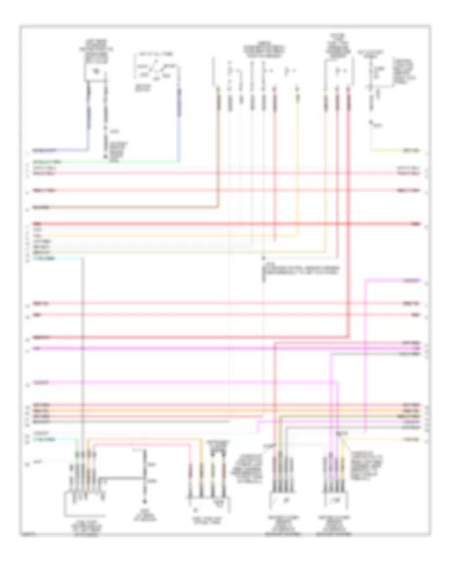
Engine Performance Wiring Diagram (2 of 5) for Lincoln Navigator 2006
List of elements for Engine Performance Wiring Diagram (2 of 5) for Lincoln Navigator 2006:
- (above accelerator pedal) accelerator pedal position sensor
- (in back-up lamp switch to rear lamp feed harness, near breakout to right side of firewall)
- (in fuel tank) fuel tank pressure transducer sensor
- (left rear of engine) heated positive crankcase ventilation (pcv) valve
- (on right rear of engine compt) g102
- Acc
- C270j
- Central junction box (cjb) (behind right kick panel)
- Fuel pump driver module (at left rear of chassis)
- Fuel tank unit (in fuel tank)
- Fuse 5a
- G403 (at rear of vehicle)
- Gnd
- Heated oxygen sensor (ho2s) 12 (on rear of exhaust system)
- Heated oxygen sensor (ho2s) 22 (on rear of exhaust system)
- Hot at all times
- Hot in start or run
- Ignition switch
- Instrument cluster system
- Lock
- Nca
- Off
- Red
- Red/pnk
- Run
- S138
- S140
- S148 (in engine control sensor harness, near breakout to left kick panel)
- S153
- S318
- S459
- S461
- Start
- Tan
Engine Performance Wiring Diagram (3 of 5) for Lincoln Navigator 2006
List of elements for Engine Performance Wiring Diagram (3 of 5) for Lincoln Navigator 2006:
- (in back-up lamp switch to rear lamp feed harness, near breakout to rear of exhaust system)
- 6hp26 automatic transmission
- C175t
- D4/d6
- Data link connector (dlc) (under left side of dash)
- Diff lock sol
- Exterior lights system
- Floor shifter
- G102 (on right rear of engine compartment)
- Ground
- Ho2s 12 htr
- Ho2s 12 sig
- Ho2s 22 htr
- Ho2s 22 sig
- Hs can +
- Hs can -
- Mtr pos rtn
- P/n pos sig
- Park neutral sig
- Position 1
- Position 2
- Position 3
- Position 4
- Powertrain control module (pcm) (on right side of firewall)
- Red
- Reversing lamps high coil rly
- Reversing lamps low coil rly
- S141
- S142
- S143
- Sig return
- Tan/red
- Transmission control switch
- Transmissions system
- Vbatt
- Vpwr
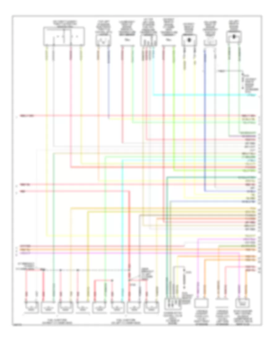
Engine Performance Wiring Diagram (4 of 5) for Lincoln Navigator 2006
List of elements for Engine Performance Wiring Diagram (4 of 5) for Lincoln Navigator 2006:
- (at breakout to right cylinder head)
- (at top left side of engine) fuel rail pressure/ temperature sensor
- (lower right front of engine) engine oil temperature (eot) sensor
- (near breakout to left cylinder head)
- (on left rear of engine) knock sensor 2
- (on lower front of engine) crankshaft position sensor
- (on right rear of engine) cylinder head temperature sensor
- (on right rear of engine) knock sensor 1
- (on right side of engine compt, on fender) g103
- (on throttle body) throttle position sensor (tps)
- (top left of engine) electronic throttle control (etc) motor
- Charge motion control valve (cmcv) (at rear of engine)
- Cmcvc
- Cmcvm
- Evap canister vent control solenoid (under rear of vehicle, above rear axle)
- Frp
- Fuel injectors (on left cylinder head)
- Fuel injectors (on right cylinder head)
- G102 (on right rear of engine compt)
- Gnd
- Nca
- Prt
- Red
- Red/pnk
- S126
- S131
- S153
- Sig rtn
- Tan
- Tan/red
- Variable camshaft timing (vct) valve 1 (right front of engine)
- Variable camshaft timing (vct) valve 2 (left side of engine)
- Vpwr
- Vref
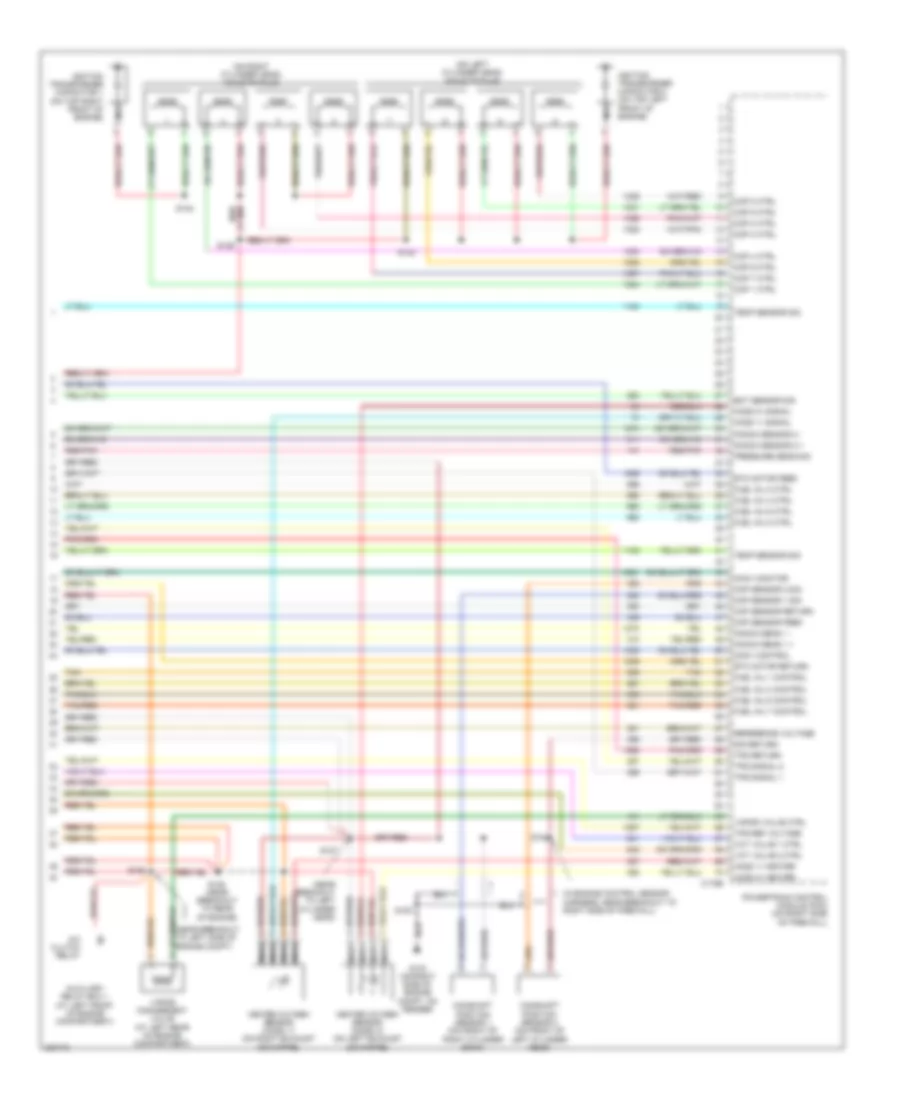
Engine Performance Wiring Diagram (5 of 5) for Lincoln Navigator 2006
List of elements for Engine Performance Wiring Diagram (5 of 5) for Lincoln Navigator 2006:
- (in engine control sensor harness, near breakout to right side of firewall)
- (near breakout to left cylinder head)
- (on left cylinder head) coils on plug
- (on right cylinder head) coils on plug
- A/c clutch relay
- Auxiliary relay box 1 (at left front of engine compartment)
- C175e
- Camshaft position sensor 1 (on front of right cylinder bank)
- Camshaft position sensor 2 (on front of left cylinder head)
- Ckp sensor feed
- Ckp sensor return
- Cmcv control
- Cmcv monitor
- Cmp sensor 1 sig
- Cmp sensor 2 sig
- Cop 1 ctrl
- Cop 2 ctrl
- Cop 3 ctrl
- Cop 4 ctrl
- Cop 5 ctrl
- Cop 6 ctrl
- Cop 7 ctrl
- Cop 8 ctrl
- Eot sensor sig
- Etc motor feed
- Etc motor return
- Fuel inj 1 control
- Fuel inj 2 ctrl
- Fuel inj 3 control
- Fuel inj 4 ctrl
- Fuel inj 5 control
- Fuel inj 6 ctrl
- Fuel inj 7 control
- Fuel inj 8 ctrl
- G103 (on right side of engine compt, on fender)
- Heated oxygen sensor (ho2s) 11 (on right exhaust downpipe)
- Heated oxygen sensor (ho2s) 21 (on left exhaust downpipe)
- Ho2s 11 heater
- Ho2s 11 signal
- Ho2s 21 heater
- Ho2s 21 signal
- Ignition transformer capacitor 1 (on top right front of engine)
- Ignition transformer capacitor 2 (on top left front of engine)
- Knock sens 1 +
- Knock sens 1 -
- Knock sensor 2 +
- Knock sensor 2 -
- Nca
- Powertrain control module (pcm) (on right side of firewall)
- Pressure sens sig
- Red/pnk
- Reference voltage
- S105
- S124
- S127
- S128 (near breakout to rear of engine)
- S129
- S132
- S153
- S154
- Sig return
- Tan
- Tan/red
- Temp sensor sig
- Tps ref voltage
- Tps return
- Tps signal 1
- Tps signal 2
- Vapor management valve (at left rear of engine compartment)
- Vapor valve ctrl
- Vct valve 1 ctrl
- Vct valve 2 ctrl

 Čeština
 Dansk
Dansk Deutsch
 Ελληνικά
 English
 Español
 Suomi
Suomi Français
 Français
 עברית
עברית Hrvatski
 Magyar
 Italiano
 日本語
日本語 한국어
한국어 Nederlands
 Polski
 Português
 Português
 Română
 Русский
 Slovenčina
 Slovenščina
 Svenska
 Türkçe
 中文 (中国)