ENGINE PERFORMANCE
4.6L
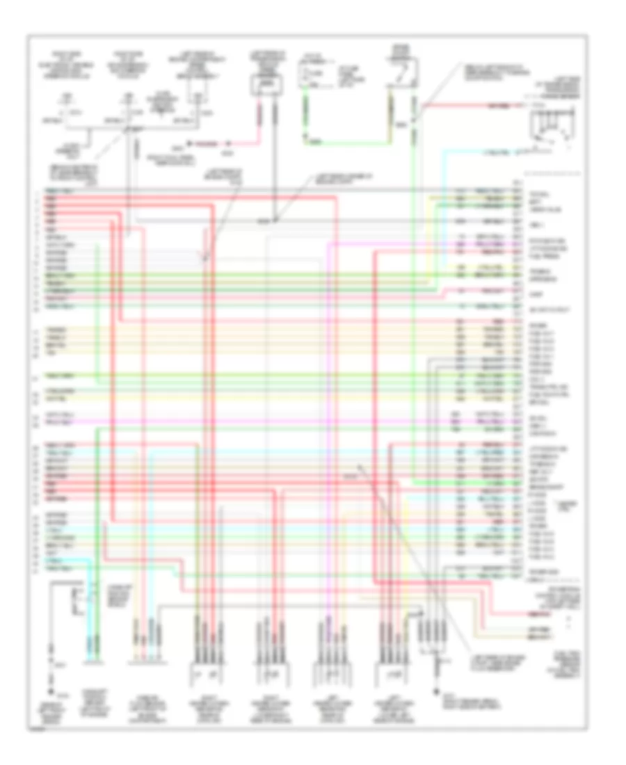
4.6L, Engine Performance Wiring Diagrams (1 of 4) for Mercury Grand Marquis LS 1997
 https://portal-diagnostov.com/license.html
Automotive Electricians Portal FZCO
Automotive Electricians Portal FZCO
https://portal-diagnostov.com/license.html
https://portal-diagnostov.com/license.html
Automotive Electricians Portal FZCO
Automotive Electricians Portal FZCO
List of elements for 4.6L, Engine Performance Wiring Diagrams (1 of 4) for Mercury Grand Marquis LS 1997:
- (front of right fender apron) g101
- (front of right fender apron)
- (inside front of right front fender)
- (left front of engine in breakout to cam- shaft position sensor)
- (left rear corner of engine compt)
- (left side of i/p, near breakout to dlc)
- (rear of left fender apron)
- (right cowl panel, near door sill)
- (top right front of engine, in breakout to right ignition coil)
- A/c clutch sig
- C2021
- Canister vent solenoid (right front of engine compt, lower side of eng compt fuse box)
- Case gnd
- Ckp (+)
- Ckp (-)
- Coil
- Coil 1
- Coil 2
- Cool fan ctrl
- Cooling fans system (cooling fan relay)
- Data link (+)
- Data link (-)
- Data link connector (left side of i/p)
- Ect sens
- Eec fuse 30a
- Egr vac reg
- Engine compartment fuse box (right front of engine compartment)
- Feps (eprom)
- Fuel flow rate
- Fuel level
- Fuel pump mon
- Fuse 15a
- Fuse 25a
- G101
- G104
- G203
- Hot at all times
- Hot in run or start
- I/p fuse panel (below left side of i/p)
- Iat sens
- Instrument cluster system (fuel gauge)
- Left ignition coil
- Left radio noise capacitor
- Maf sig rtn
- Mil
- Nca
- Octane adjust
- Pcm power diode
- Pcm power relay
- Powertrain control module (top left side of safety wall)
- Pwr gnd
- Red
- Relay center (left side of engine compartment)
- Right ignition coil
- Right radio noise capacitor
- Rt ho2s #2 sig
- S100
- S101
- S102
- S103
- S105
- S106
- S116
- S117
- S118
- S129
- S276
- Shift sol 1
- Shift sol 2
- To spark plugs 1 & 6
- To spark plugs 2 & 8
- To spark plugs 3 & 5
- To spark plugs 4 & 7
- Trans ctrl sw
- Trans temp
- Transmission control switch
- Vss (-)
4.6L, Engine Performance Wiring Diagrams (2 of 4) for Mercury Grand Marquis LS 1997
List of elements for 4.6L, Engine Performance Wiring Diagrams (2 of 4) for Mercury Grand Marquis LS 1997:
- (a/c high pressure cut out switch) air conditioning system
- (left rear of engine compt)
- (left side of engine compt)
- (left side of engine compt, near breakout to fuel pump prime connector)
- (speedometer/ odometer) vehicle speed input
- C255
- Crankshaft position (ckp) sensor (lower right front of engine)
- Crankshaft position sensor shield
- Differential pressure feedback egr sensor (near right side of intake manifold)
- Digital only
- Engine compartment fuse box (right front of engine compartment)
- Engine coolant temperature sensor (top left front of engine)
- Fuel flow rate input
- Fuel pmp fuse 20a
- Fuel pump prime connector (left side of engine compartment)
- Fuel pump relay
- G104 (rear of left front fender apron)
- Hot at all times
- Instrument cluster
- Intake air temperature sensor (rear of air cleaner assembly)
- Malfunction indicator input
- Octane adjust plug (left side of engine compartment)
- Red
- Relay center (left side of engine compartment)
- S101
- S110
- S124
- S125
- S126 (lower right rear of engine, near breakout to right heated oxygen sensor 1)
- S130
- S147
- Throttle position sensor (left side of throttle body)
- Transmission control indicator input
- Wot cutout relay
4.6L, Engine Performance Wiring Diagrams (3 of 4) for Mercury Grand Marquis LS 1997
List of elements for 4.6L, Engine Performance Wiring Diagrams (3 of 4) for Mercury Grand Marquis LS 1997:
- (center rear of engine, in breakout to dpfe sensor)
- (left front of trunk) inertia fuel shutoff switch
- (on engine, near breakout to fuel injector 8) s131
- (rear center of of engine) compartment)
- (right cowl panel, near door sill)
- 4r70w transmission
- Egr vacuum regulator solenoid (top center rear of engine)
- Electronic pressure control solenoid
- Evaporative emission (evap) canister purge valve
- Fuel injectors
- Fuel pump/ fuel gauge sender
- Fuel tank assembly
- G203
- Idle air control valve (left side of intake manifold)
- Nca
- Output shaft speed sensor (left rear of transmission)
- Red
- S143
- S148 (left side of engine compt)
- S402
- Shift solenoids
- Ss1
- Ss2
- Tan
- Tan/ red
- Tan/red
- Torque converter clutch solenoid
- Transmission fluid temperature sensor
4.6L, Engine Performance Wiring Diagrams (4 of 4) for Mercury Grand Marquis LS 1997
List of elements for 4.6L, Engine Performance Wiring Diagrams (4 of 4) for Mercury Grand Marquis LS 1997:
- (behind center of i/p, near breakout to front control unit)
- (below left side of i/p, near breakout to brake on/off switch)
- (left rear corner of engine compt)
- (left rear of engine compartment) speed control servo assembly
- (left rear of engine compt) s147
- (left rear of engine compt, near brake fluid reservoir)
- (left rear of transmission) vehicle speed sensor
- (left side of transmission) transmission range sensor
- (rear of left front fender apron)
- (right cowl panel, near door sill)
- (right side of i/p) air suspension/ evo steering module
- (right side of i/p) electronic variable orifice (evo) steering module
- A/c wot cutout
- Batt
- Brake on/off
- Brake on/off switch
- C214
- C216
- C234
- Cam pos in
- Camshaft position sensor (left front of engine)
- Camshaft position sensor shield
- Canp
- Coil 3
- Coil 4
- Dpfe sens
- Epc sol
- Fuel inj 1
- Fuel inj 2
- Fuel inj 3
- Fuel inj 4
- Fuel inj 5
- Fuel inj 6
- Fuel inj 7
- Fuel inj 8
- Fuel press
- Fuel pump ctrl
- Fuel tank pressure sensor (in fuel tank assembly)
- Fuse 15a
- G101 (right fender apron, right side of battery)
- G104
- G203
- Heater ctrl
- Hot at all times
- I/p fuse panel (left side of i/p)
- Iac sol
- L ho2s
- Left heated oxygen sensor #1 (lower left rear of engine)
- Left heated oxygen sensor #2 (rear of catalyst)
- Lft ho2s #1 sig
- Lft ho2s #2 sig
- Maf sens in
- Mass air flow sensor (left front of engine compartment)
- Nca
- Oss (+)
- Power
- Power gnd
- Powertrain control module (top left side of safety wall)
- Pwr gnd
- R ho2s
- Red
- Red/pnk
- Ref volt
- Right heated oxygen sensor #1 (lower right rear of engine)
- Right heated oxygen sensor #2 (rear of catalyst)
- Rt ho2s #1 sig
- S101
- S105
- S106
- S109
- S114
- S115
- S247
- S258
- S263
- Sig rtn
- Tan
- Tan/red
- Tcc sol
- Tp sens in
- Tr sens
- Trans ctrl ind
- Vapor valve
- Vss (+)
- Vss (-)
- W/ air suspension and evo steering
- W/ evo steering only

 Čeština
 Dansk
Dansk Deutsch
 Ελληνικά
 English
 Español
 Suomi
Suomi Français
 Français
 עברית
עברית Hrvatski
 Magyar
 Italiano
 日本語
日本語 한국어
한국어 Nederlands
 Polski
 Português
 Português
 Română
 Русский
 Slovenčina
 Slovenščina
 Svenska
 Türkçe
 中文 (中国)