ENGINE PERFORMANCE
3.0L
3.0L, Engine Performance Wiring Diagrams (1 of 3) for Mercury Villager Nautica 1997
 https://portal-diagnostov.com/license.html
Automotive Electricians Portal FZCO
Automotive Electricians Portal FZCO
https://portal-diagnostov.com/license.html
https://portal-diagnostov.com/license.html
Automotive Electricians Portal FZCO
Automotive Electricians Portal FZCO
List of elements for 3.0L, Engine Performance Wiring Diagrams (1 of 3) for Mercury Villager Nautica 1997:
- mil
- (electronic) (analog)
- (engine control harness, breakout to center rear of engine compt.)
- (engine control harness, breakout to pcm)
- (engine control harness, near breakout to center rear of eng compt)
- (engine control harness, near breakout to pcm)
- (engine control harness, near breakout to right rear of engine)
- (engine control sub harness, near breakout to center rear of eng compt)
- (top of engine)
- A/c high pressure switch
- A/c relay
- Achps
- Acr
- Av01
- Av02
- Av04
- Av12
- Av20
- Av22
- Av23
- Av28
- Av30
- Av31
- Av32
- Av33
- Av34
- Av36
- Av40
- Av53
- Av56
- Av57
- Av58
- Av61
- Av73
- Av91
- Avo5
- C272 c268
- Ckp
- Ckpref
- Cluster
- Cooling fan relays
- Crankshaft position (ckp) sensor (below
- Data link connector (dlc) (left side of engine compartment, near battery)
- Distributor)
- Dlc
- Egr temperature (egrt) sensor (on underside of throttle body, air intake)
- Eng cont fuse 10a
- Engine compartment fuse/relay panel
- Engine compartment)
- Engine coolant temperature (ect) sensor (top right rear
- Engine, on throttle body)
- Ep06
- Ep13
- Es39
- Es48
- Fa06
- Fa12
- Ffs
- Fuse 10a
- Fuse 7.5a
- G134
- G134 (top of engine)
- Gnd
- Ha41
- Hfan1/hfan2 ry
- Hot at all times
- Hot in start
- Hot in start or run
- Hps
- Hx01
- I/p fuse/ relay panel
- Iat
- Ign
- Ings
- Inj3
- Instrument
- Instrument cluster
- Intake air temperature (iat) sensor (left front corner of
- Isi
- Lo fan ry
- Nca
- Nr01
- Of engine)
- Pcm
- Pcm in
- Pcmr
- Pnk
- Pnps
- Powertrain control module (pcm) (behind top right side of i/p, behind glove box)
- Powertrain control module (pcm) relay (behind right side of i/p)
- Psg
- Psp
- Red
- Res input
- Rpm
- S108
- S110
- S112
- S131
- S134
- S135
- S136
- S154
- S218
- S222
- S238
- S241
- S242
- S254 (main harness, near breakout behind center of i/p)
- S265
- S266
- S269
- S277 (eng. control harness, near breakout to center rear of eng compt)
- S278
- S278 (transmission harness, near breakout to top right side of i/p)
- Speed control module
- Speed signal output
- St sig
- Tcm
- Tcm (tp)
- Throttle position (tp) sensor (top left rear of
- Throttle position (tp) switch (top left rear of
- Tp in
- Tp ref
- Tp sw
- Transaxle control module
- Transaxle control module (tcm) (behind top right side of i/p, behind glove box)
- Transmissions system
- Vss
- W/ electronic cluster
- Wot in
- Zy13
- Zy14
- Zy21
- Zy31
- Zy34
- Zy35
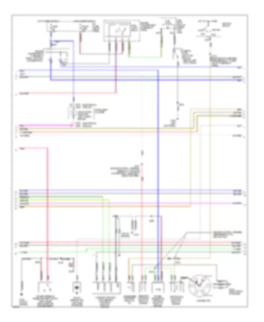
3.0L, Engine Performance Wiring Diagrams (2 of 3) for Mercury Villager Nautica 1997
 https://portal-diagnostov.com/license.html
Automotive Electricians Portal FZCO
Automotive Electricians Portal FZCO
https://portal-diagnostov.com/license.html
https://portal-diagnostov.com/license.html
Automotive Electricians Portal FZCO
Automotive Electricians Portal FZCOList of elements for 3.0L, Engine Performance Wiring Diagrams (2 of 3) for Mercury Villager Nautica 1997:
- (analog)
- (electronic)
- (engine control harness, near breakout to ignition coil)
- (left kick panel)
- (top of engine)
- (top right front of engine)
- Acc
- C268
- C276
- Camshaft position (cmp) sensor
- Ckp out
- Ckp ref
- Condenser (top right front of i/p)
- Distributor
- Engine compartment fuse/relay panel
- Engine compartment fuse/relay panel junction connector #1
- F pump fuse 15a
- Fuel pump
- Fuel pump module (inside fuel tank)
- Fuel pump relay
- Fuse 10a
- G119 (right front of engine)
- G134
- G134 (top of engine)
- G200
- Gnd
- Hot at all times
- Hot in start or run
- I/p fuse/ relay panel
- Ignitiion switch
- Ignition coil (top right front of engine)
- Inertia fuel shut-off switch (behind left cowl panel)
- Instrument cluster
- Knock sensor (ks) (left side of engine)
- Lock
- Malfunction indicator lamp "check engine"
- Nca
- Pnk
- Power steering pressure (psp) switch (right rear side of engine compartment)
- Power transistor (top right front of engine)
- Pwr in
- Red
- Resistor (top right front of engine)
- Run
- S109
- S119 (engine room harness, near breakout to eng compt fuse/relay panel)
- S120
- S121 (engine control harness, breakout to engine compartment, near right side of battery)
- S128
- S222
- S299
- S300
- Start
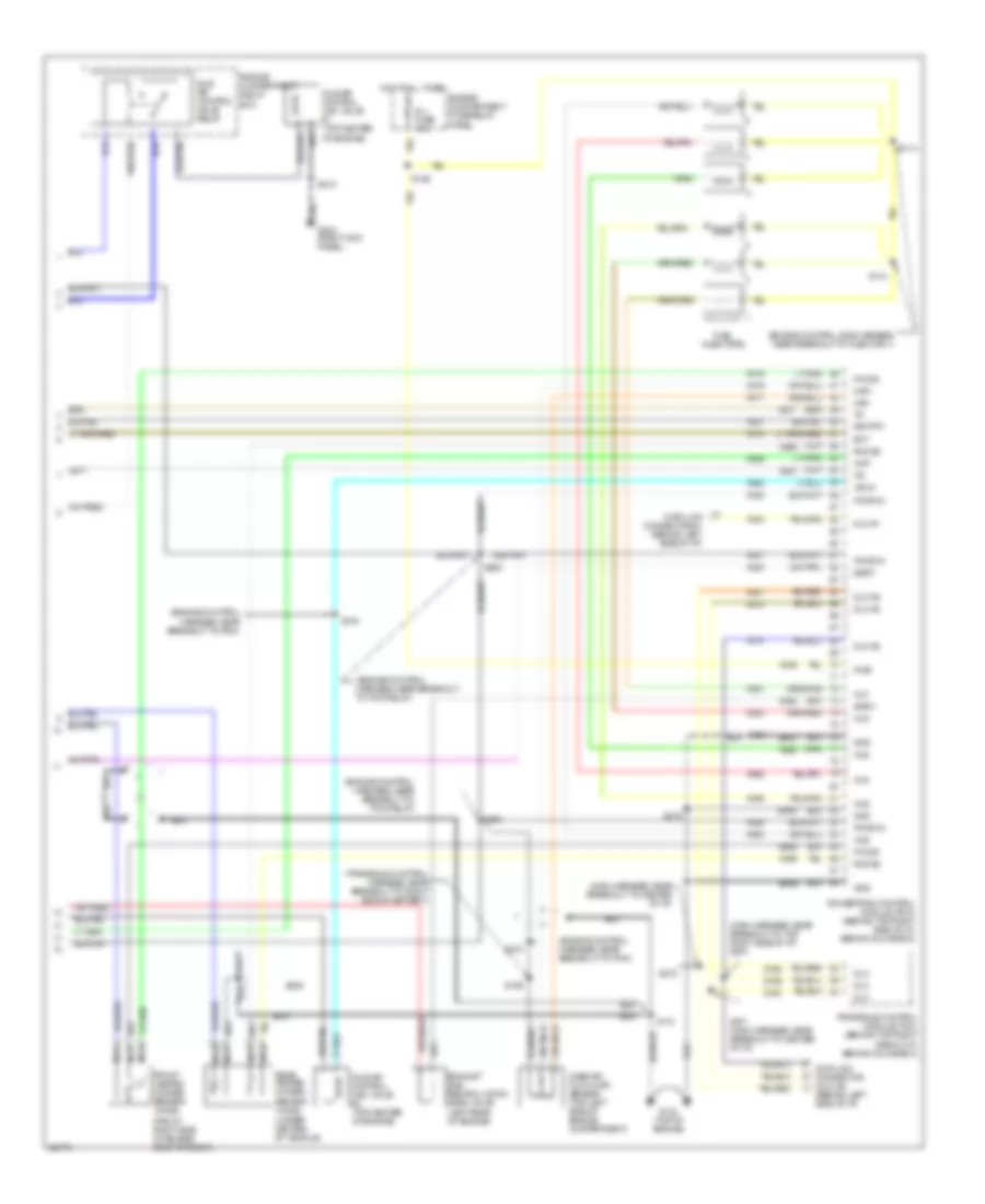
3.0L, Engine Performance Wiring Diagrams (3 of 3) for Mercury Villager Nautica 1997
 https://portal-diagnostov.com/license.html
Automotive Electricians Portal FZCO
Automotive Electricians Portal FZCO
https://portal-diagnostov.com/license.html
https://portal-diagnostov.com/license.html
Automotive Electricians Portal FZCO
Automotive Electricians Portal FZCOList of elements for 3.0L, Engine Performance Wiring Diagrams (3 of 3) for Mercury Villager Nautica 1997:
- (behind left side of i/p)
- (engine control harness, near breakout to pcm relay)
- (engine control harness, near breakout to pcm)
- (engine control sub harness, near breakout to injector 1)
- (front right side of engine compartment)
- (main harness, near breakout to center of i/p)
- (main harness, near breakout to top right side of i/p) s273
- (transaxle control harness, near breakout to right side of battery)
- (under center of vehicle)
- Av07
- Av08
- Av09
- Av14
- Av15
- Av16
- Av17
- Av18
- Av19
- Av21
- Av27
- Av37
- Av38
- Av42
- Av46
- Av47
- Av51
- Av52
- Av53
- Av55
- Av59
- Av60
- Av62
- Av63
- Av64
- Av66
- Av99
- Cmp
- Data link connector #1 (behind left side of i/p)
- Data link connector (dlc) #2
- Dlc
- Dlc #1
- Dlc #2
- Ect
- Egrt
- Egrv
- Engine compartment fuse/relay panel
- Engine compartment relay box
- Ep57
- Ep58
- Ep66
- Es90
- Exhaust gas recirculation (egr) valve (left rear of engine)
- Fho2s
- Front heated oxygen sensor (ho2s)
- Fuel injectors
- G134 (top of engine)
- G203 (right kick panel)
- Gnd
- Hot at all times
- Iacv2
- Idle air control (iac) valve #1 (top center of engine)
- Idle air control (iac) valve #2 (top center of engine)
- Idle air control valve relay
- Inj fuse 10a
- Inj1
- Inj2
- Inj3
- Inj4
- Inj5
- Inj6
- Maf+
- Maf-
- Mass air flow (maf) sensor (top left side of engine compartment)
- Nca
- Pcmr in
- Powertrain control module (pcm) (behind top right side of i/p, behind glove box)
- Pwr
- Rear heated oxygen sensor (ho2s)
- Rho2s
- S110
- S114
- S118
- S129
- S130
- S156
- S210
- S218
- S219
- S263
- S264
- S270
- S271 (main harness, near breakout to center of i/p)
- S272
- S308
- Sig rtn
- Transaxle control module (tcm) (behind top right side of i/p, behind glove box)
- Zy28
- Zy29
- Zy30

 Čeština
 Dansk
Dansk Deutsch
 Ελληνικά
 English
 English
 Español
 Suomi
Suomi Français
 Français
 עברית
עברית Hrvatski
 Magyar
 Italiano
 日本語
日本語 한국어
한국어 Nederlands
 Polski
 Português
 Português
 Română
 Русский
 Slovenčina
 Slovenščina
 Svenska
 中文 (中国)
