ENGINE PERFORMANCE
2.4L
2.4L, Engine Performance Wiring Diagrams (1 of 3) for Nissan Altima GLE 2000
 https://portal-diagnostov.com/license.html
Automotive Electricians Portal FZCO
Automotive Electricians Portal FZCO
https://portal-diagnostov.com/license.html
https://portal-diagnostov.com/license.html
Automotive Electricians Portal FZCO
Automotive Electricians Portal FZCO
List of elements for 2.4L, Engine Performance Wiring Diagrams (1 of 3) for Nissan Altima GLE 2000:
- (behind left side of dash) data link connector
- (on intake manifold)
- Abs control module (at left kick panel)
- Absolute pressure sensor (behind left instrument lower cover)
- Air conditioning system
- Cooling fans system
- Defogger system
- Eccs control module (ecm) (behind instrument panel lower cover)
- Eccs relay (behind instrument panel lower cover)
- Egr temper- ature sensor (near base of egr valve)
- Engine coolant temperature sensor (left side of eng, near fuel inj 1)
- Evap canister purge volume control solenoid valve (top right side of eng)
- Evap control system pressure sensor (under left rear corner of vehicle)
- Fuel level
- Fuel level sensing unit (in fuel tank)
- Fuel temp
- Fuse & fusible link box (left side of engine compt)
- Fuse 10a
- G131
- G904 (left "c" pillar)
- Headlight system
- Hot at all times
- Instrument cluster system (tach)
- Knock sensor (on right side of eng)
- Mass airflow sensor (left side of eng compt, in air intake)
- Nca
- Red
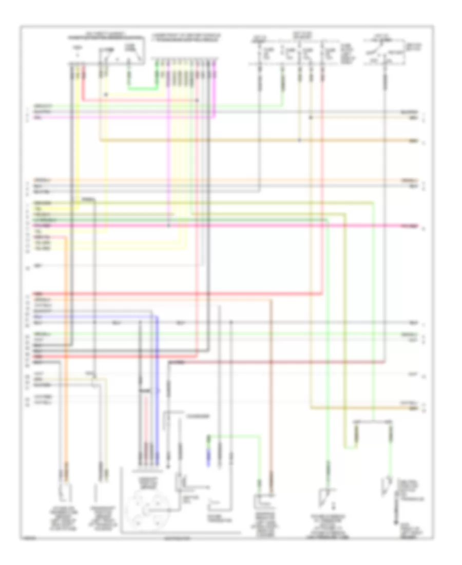
2.4L, Engine Performance Wiring Diagrams (2 of 3) for Nissan Altima GLE 2000
List of elements for 2.4L, Engine Performance Wiring Diagrams (2 of 3) for Nissan Altima GLE 2000:
- (on throttle body) throttle position sensor & switch
- (under front of center console) transmission control module
- A/t
- Acc
- Camshaft position sensor
- Closed
- Condenser
- Crankshaft position sensor (left front of transaxle housing)
- Distributor
- Dropping resistor (left side of eng compt, near air cleaner)
- Fuse 10a
- Fuse block (left side of dash)
- G100 (front of left front fender)
- Hot at all times
- Hot in on or start
- Hot in start
- Ignition coil
- Ignition switch
- Intake air temperature sensor (left side of eng compt, in air intake)
- M/t
- Nca
- Neutral position switch (on transaxle)
- Off
- Power steering oil pressure switch (attached to power steering high pressure tube)
- Power transistor
- Red
- Start
- Wide open
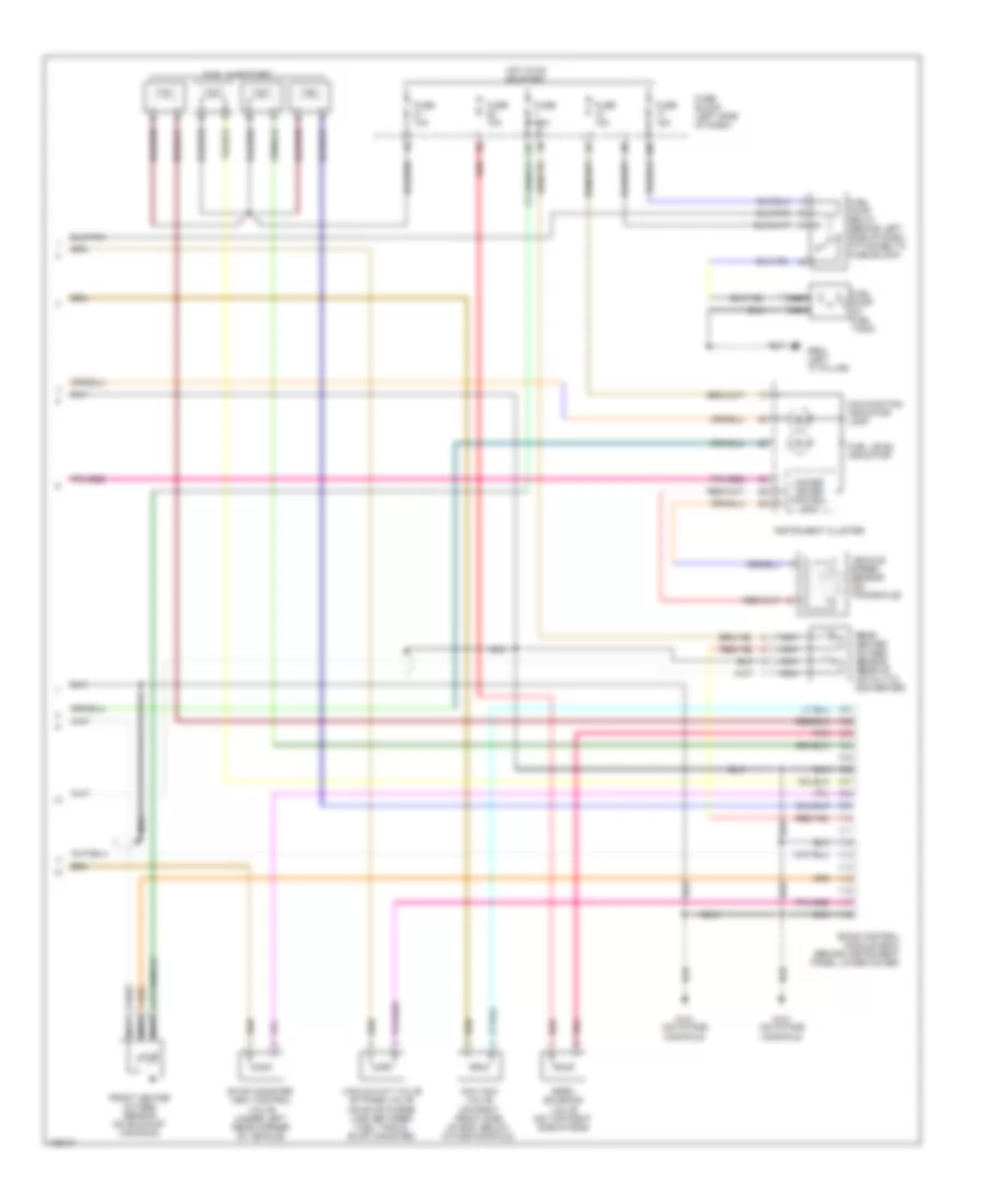
2.4L, Engine Performance Wiring Diagrams (3 of 3) for Nissan Altima GLE 2000
List of elements for 2.4L, Engine Performance Wiring Diagrams (3 of 3) for Nissan Altima GLE 2000:
- 10n
- 13k
- 1o1
- Eccs control module (ecm) (behind instrument panel lower cover)
- Egrc solenoid valve (on top right side of eng)
- Evap canister vent control valve (under left rear corner of vehicle)
- Front heated oxygen sensor (on exhaust manifold)
- Fuel injectors
- Fuel level indicator
- Fuel pump (in fuel tank)
- Fuel pump relay (behind left side of dash, attached to fuse block)
- Fuse 10a
- Fuse 15a
- Fuse block (left side of dash)
- G131 (on intake manifold)
- G904 (left "c" pillar)
- Hot in on or start
- Iacv-aac valve (on right front side of eng, below intake manifold)
- Instrument cluster
- Malfunction indicator lamp
- Nca
- Pnk
- Rear heated oxygen sensor (rear of catalytic converter)
- Red
- Unified meter control unit
- Vacuum cut valve by-pass valve (on evap purge line, between fuel tank & evap canister)
- Vehicle speed sensor (on transaxle)

 Čeština
 Dansk
Dansk Deutsch
 Ελληνικά
 English
 Español
 Suomi
Suomi Français
 Français
 עברית
עברית Hrvatski
 Magyar
 Italiano
 日本語
日本語 한국어
한국어 Nederlands
 Polski
 Português
 Português
 Română
 Русский
 Slovenčina
 Slovenščina
 Svenska
 Türkçe
 中文 (中国)