ENGINE PERFORMANCE
2.5L
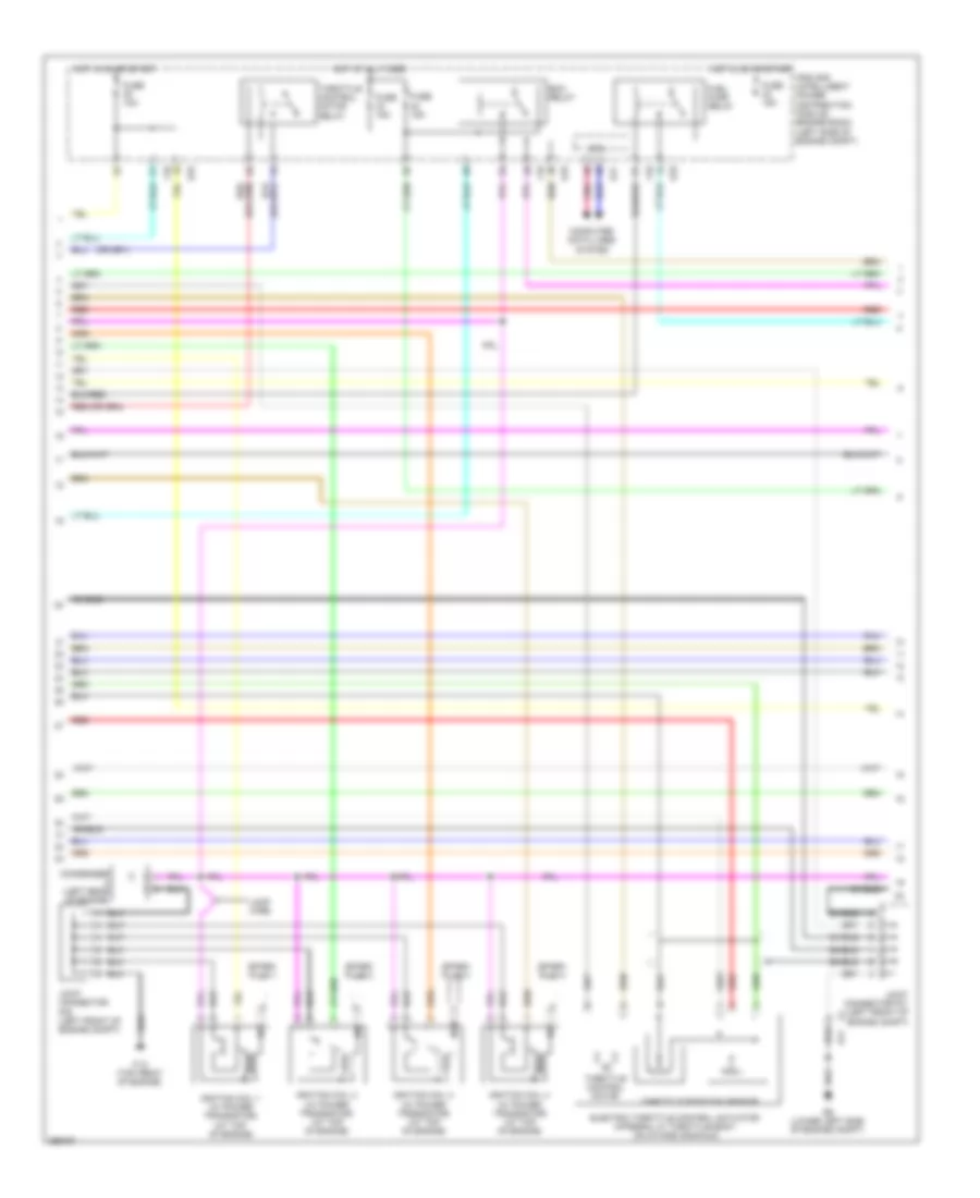
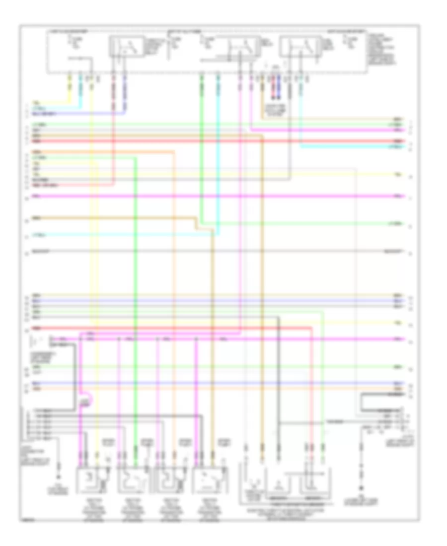
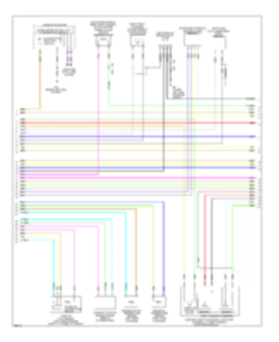
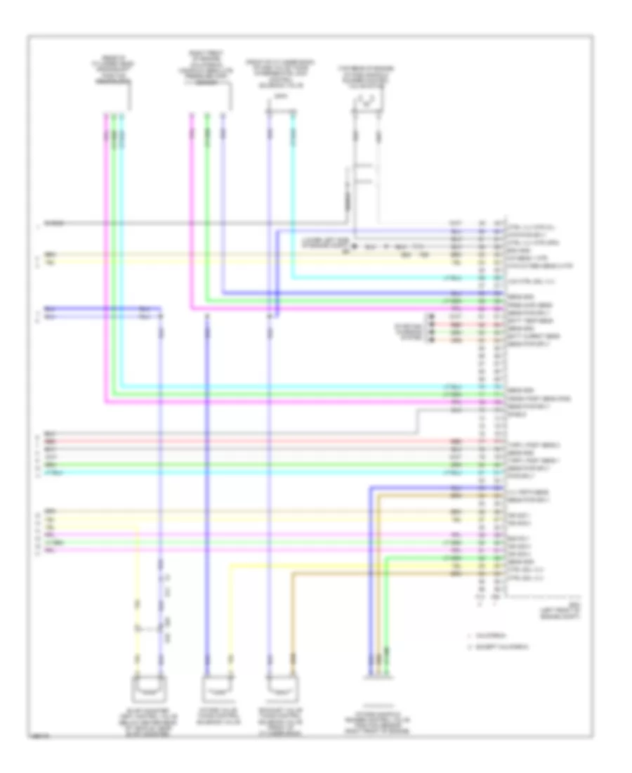
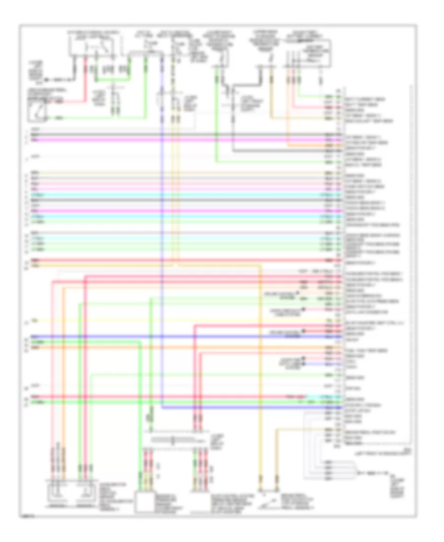
2.5L, Engine Performance Wiring Diagram, Coupe California (1 of 4) for Nissan Altima S 2013
 https://portal-diagnostov.com/license.html
Automotive Electricians Portal FZCO
Automotive Electricians Portal FZCO
https://portal-diagnostov.com/license.html
https://portal-diagnostov.com/license.html
Automotive Electricians Portal FZCO
Automotive Electricians Portal FZCO
List of elements for 2.5L, Engine Performance Wiring Diagram, Coupe California (1 of 4) for Nissan Altima S 2013:
- (behind left end of dash)
- 12m
- 3rdo2h
- 3rdo2s
- Af+1
- Af-1
- Afh1
- Avcc1-cursen
- Avcc1-pspres
- Avcc1-tps-b1
- Battery current sensor (on battery)
- Combination meter
- Computer data lines system
- Cursen
- E11
- E18
- E44
- E9 (lower left side of engine compt)
- Ecm (left front of engine compt)
- Engine coolant temperature sensor (left rear of engine)
- Evap
- Evap canister purge volume control solenoid valve (on intake manifold, near throttle body)
- F1 e3
- F90
- F91
- Fpr
- Fuel injectors (top of engine)
- Fuse 10a
- Fuse block (j/b)
- Gnd
- Gnda-cursen
- Gnda-o2sr2
- Gnda-pdres
- Gnda-pspres
- Gnda-ta1
- Gnda-tps-b1
- Gnda-tw
- Hot in on or start
- Ign 1
- Ign 2
- Ign 3
- Ign 4
- Inj 1
- Inj 2
- Inj 3
- Inj 4
- Ipdm e/r (intelligent power distribution e201
- Joint connector f04 (left front of engine compt)
- Joint connector f06 (left front of engine compt)
- Joint connector f07 (left side of engine compt)
- Junction block (left end of dash)
- M57 (behind left end of dash)
- Malfunction indicator lamp
- Module engine room) (left side of engine compt)
- Motor1-b1
- Motor2-b1
- Motrly-b1
- O2hr1
- Osr1
- Pdpres
- Pnk
- Power steering pressure sensor
- Pspres
- Red
- Refrigerant pressure sensor (left front of engine compt)
- Scv1
- Scv2
- Scvpos
- Shield
- Ssof
- Ta1
- Tps1-b1
- Tps2-b1
- Tumble control valve actuator
- Tumble control valve motor
- Tumble control valve position sensor
- Unified meter (w/ information display)
- Vmot-b1
- Vscv
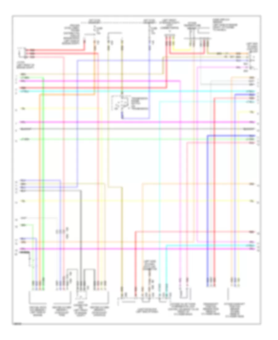
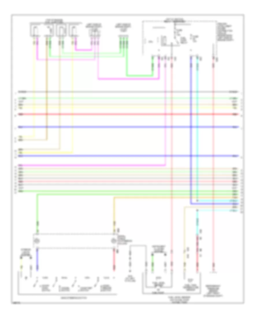
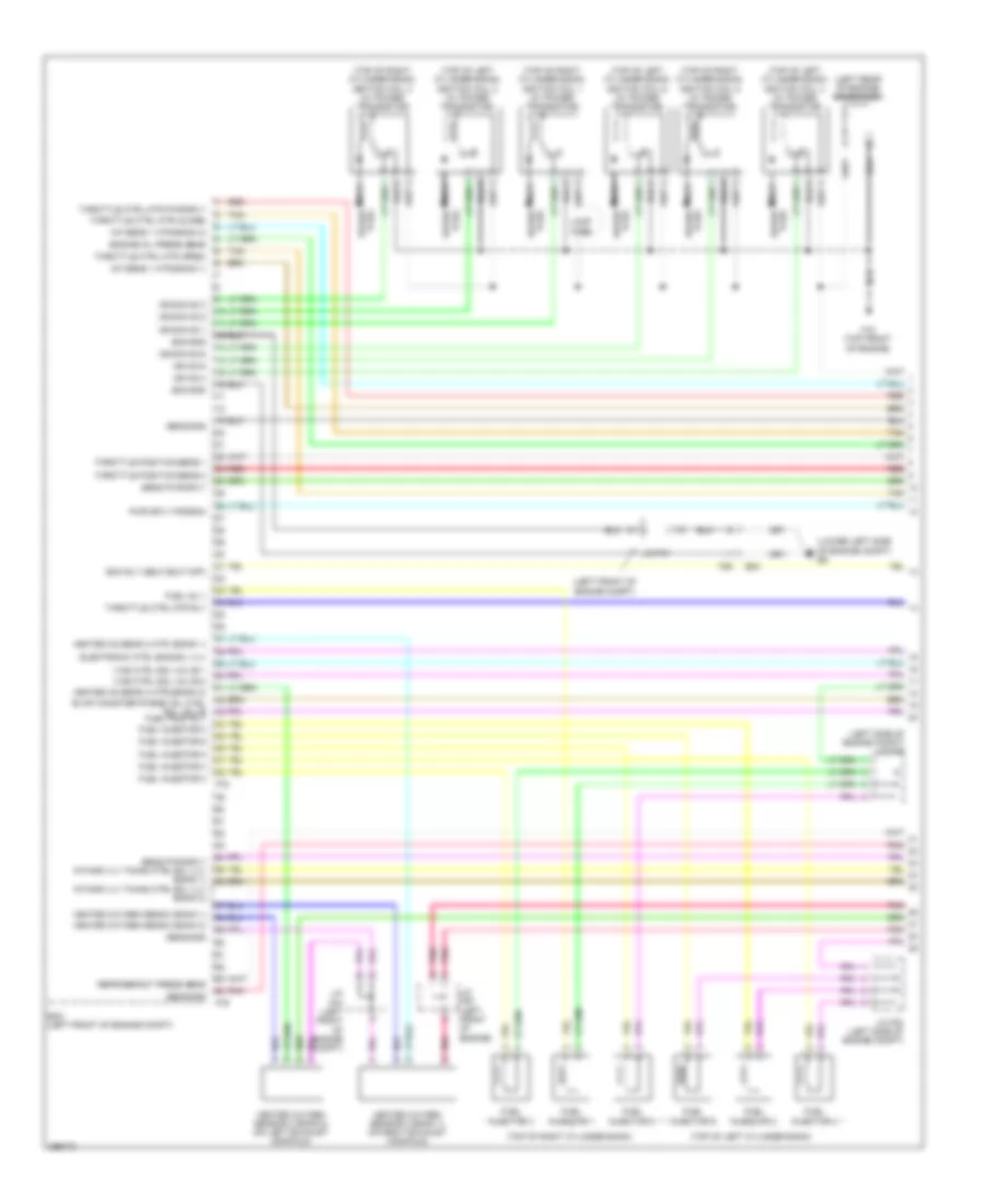
2.5L, Engine Performance Wiring Diagram, Coupe California (2 of 4) for Nissan Altima S 2013
List of elements for 2.5L, Engine Performance Wiring Diagram, Coupe California (2 of 4) for Nissan Altima S 2013:
- Computer data lines system
- Condenser (left rear of engine)
- Cpu
- E11
- E17
- E18
- E9 (lower left side of engine compt)
- Ecm relay
- Electric throttle control actuator (integral w/ throttle body, on intake manifold)
- F10
- F15 (top front of engine)
- Fuel pump relay
- Fuse 10a
- Fuse 15a
- Hot at all times
- Hot in on or start
- Ignition coil 1 (w/ power transistor) (at top of engine)
- Ignition coil 2 (w/ power transistor) (at top of engine)
- Ignition coil 3 (w/ power transistor) (at top of engine)
- Ignition coil 4 (w/ power transistor) (at top of engine)
- Ipdm e/r (intelligent power distribution module engine room) (left side of engine compt)
- Joint connector f01 (left front of engine compt)
- Joint connector f05 (left front of engine compt)
- Loop wire
- Pnk
- Red
- Shield
- Spark plug 1
- Spark plug 2
- Spark plug 3
- Spark plug 4
- Throttle control motor
- Throttle control motor relay
- Throttle position sensor
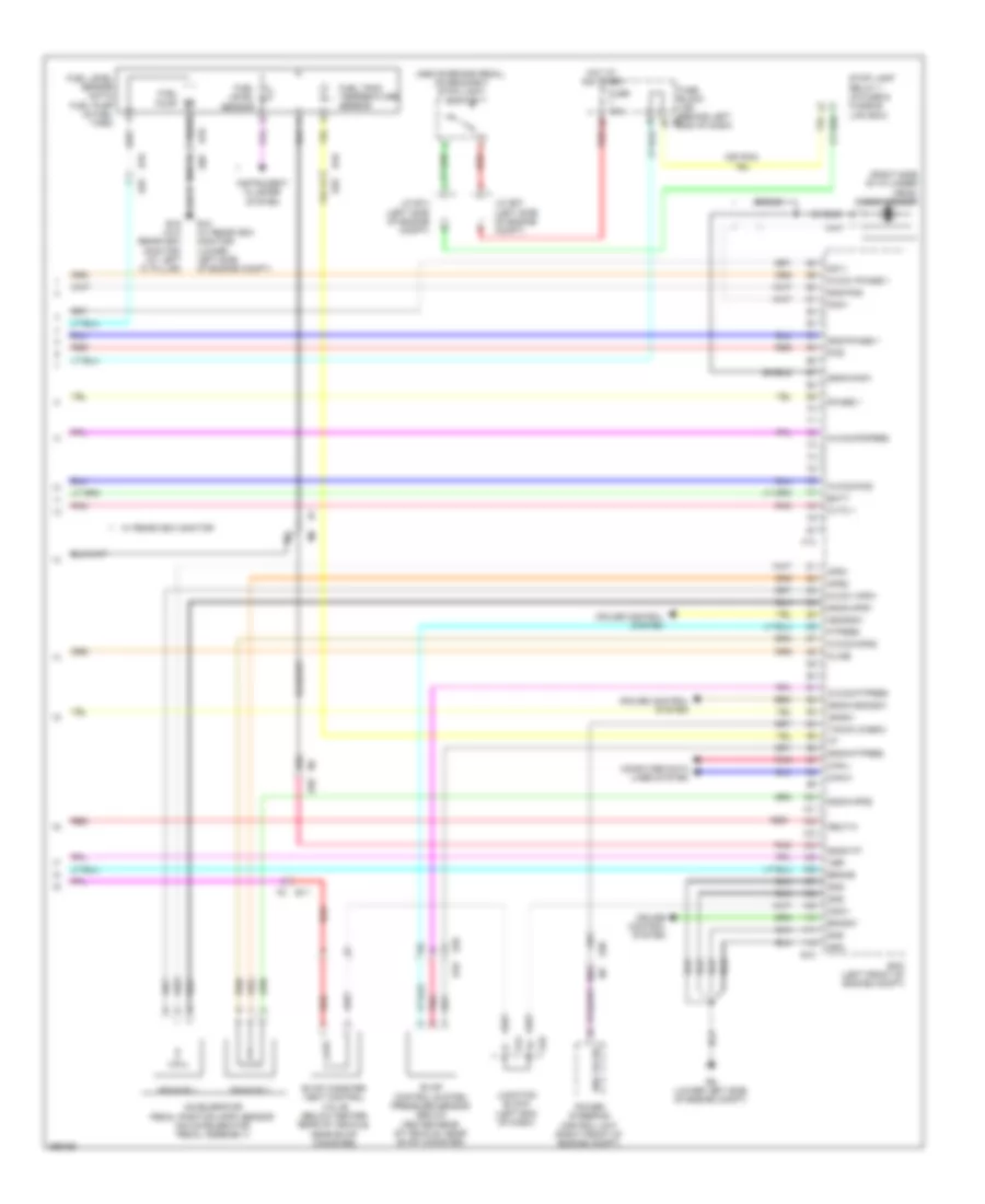
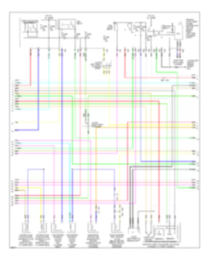
2.5L, Engine Performance Wiring Diagram, Coupe California (3 of 4) for Nissan Altima S 2013
List of elements for 2.5L, Engine Performance Wiring Diagram, Coupe California (3 of 4) for Nissan Altima S 2013:
- (left end of dash) junction block
- (left front of engine compt) joint connector f06
- (left side of dash) data link connector
- 34g
- Air fuel ratio (a/f) sensor 1 (left side of engine)
- Crankshaft position sensor (pos) (rear of cylinder head)
- E11
- E18
- E44
- E45
- E46
- E50
- F10
- F52
- F58 f204
- Fuse 10a
- Fuse 15a
- Heated oxygen sensor 2 (on exhaust (manifold)
- Heated oxygen sensor 3 (in exhaust pipe)
- Hot in on or start
- Intake camshaft position sensor (phase) (rear of cylinder head)
- Intake temperature sensor
- Intake valve timing intermediate lock control solenoid valve (front of cylinder bank)
- Ipdm e/r (intelligent power distribution module engine room) (left side of engine compt)
- J/c f04 (left front of engine compt)
- Joint connector f06 (left front of engine compt)
- Junction block (left end of dash)
- M1 e30
- Mass airflow sensor (left side of engine compt, attached to air box)
- N r
- Pnk
- Red
- Shield
- Transmission range switch (on transmission)
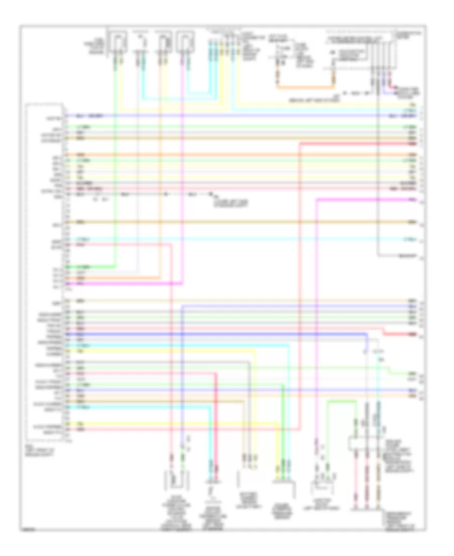
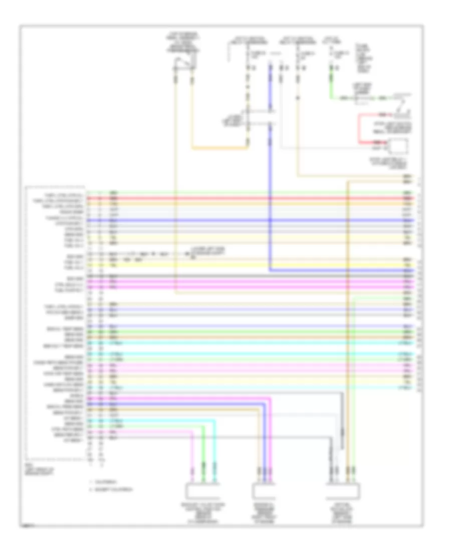
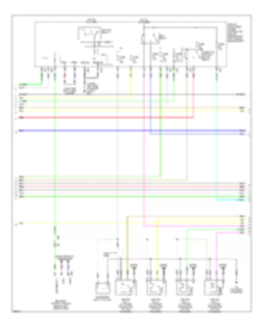
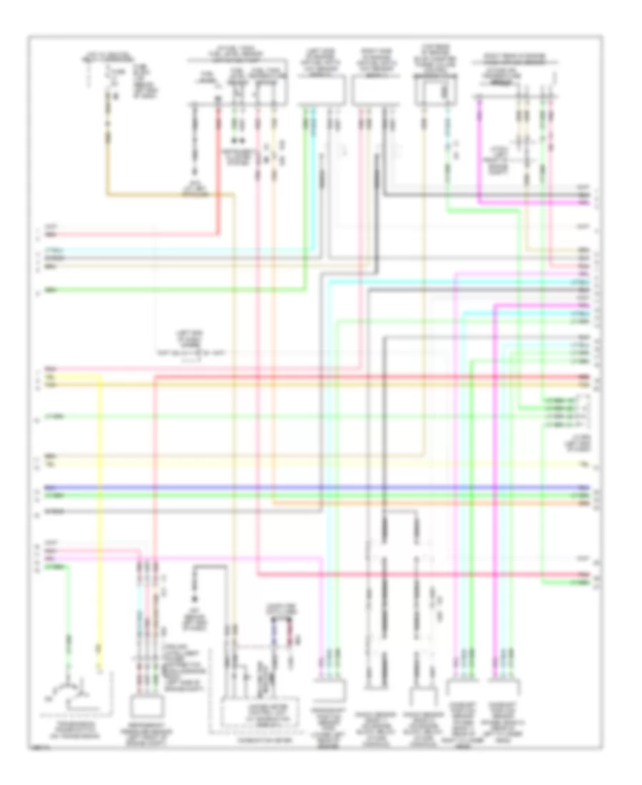
2.5L, Engine Performance Wiring Diagram, Coupe California (4 of 4) for Nissan Altima S 2013
List of elements for 2.5L, Engine Performance Wiring Diagram, Coupe California (4 of 4) for Nissan Altima S 2013:
- (above brake pedal, on bracket) stop light switch
- (or pnk)
- (right side of cylinder head) knock sensor
- 30j
- 60g
- 63g
- Accelerator pedal position (app) sensor (on accelerator pedal assembly)
- Aps1
- Aps2
- Ascdsw
- Avcc1-aps1
- Avcc1-phase 1
- Avcc2-aps2
- Avcc2-ftpres
- Avcc2-pdpres
- Avcc2-pos
- B10
- B10 e29
- B19 (w/o rearview monitor) (at left "c" pillar)
- Batt
- Bncsw
- Brake
- Can-h
- Can-l
- Cdcv
- Computer data lines system
- Cruise control system
- Cvtc 1
- E15 (w/ rearview monitor) (lower left side of engine compt)
- E29
- E29 b10
- E30 m1
- E31
- E44
- E45
- E9 (lower left side of engine compt)
- Ecm (left front of engine compt)
- Eng tach
- Evap canister vent control valve (below center rear of vehicle, near evap canister)
- Evap control system pressure sensor (below center rear of vehicle, near evap canister)
- F2 e11
- F90
- Ftpres
- Fuel level sensor
- Fuel level sensor unit & fuel pump (in fuel tank)
- Fuel pump
- Fuel tank temperature sensor
- Fuse 10a
- Fuse block (j/b) (behind left e6 end of dash)
- Gnd
- Gnd-phase 1
- Gnd-pos
- Gnda-aps1
- Gnda-aps2
- Gnda-ascdsw
- Gnda-ftpres
- Gnda-knk1
- Gnda-tf
- Hot at all times
- Ignsw
- Instrument cluster system
- J/c e07 (left side of engine compt)
- J/c e14 (left side of engine compt)
- Junction block (left end of dash)
- Kline
- Knk1
- M1 e30
- Neut-h
- Phase 1
- Pnk
- Pos
- Power steering control unit (right front of engine compt)
- Qa1+
- Red
- Sensor 1
- Sensor 2
- Shield
- Stop lamp relay 1 (in fuse & fusible link box)
- Tacho (cabin)
- Vbr
- W/ rearview monitor
2.5L, Engine Performance Wiring Diagram, Coupe Except California (1 of 4) for Nissan Altima S 2013
List of elements for 2.5L, Engine Performance Wiring Diagram, Coupe Except California (1 of 4) for Nissan Altima S 2013:
- (or red)
- 12m
- Af+1
- Af-1
- Afh1
- Avcc1-cursen
- Avcc1-pspres
- Avcc1-tps-b1
- Battery current sensor (on battery)
- Combination meter
- Computer data lines system
- Cursen
- E11
- E18
- E44
- E45
- E9 (lower left side of engine compt)
- Ecm (left front of engine compt)
- Engine coolant temperature sensor (left rear of engine)
- Evap
- Evap canister purge volume control solenoid valve (on intake manifold, near throttle body)
- F13
- F14
- Fpr
- Fuel injectors (top of engine)
- Fuse 10a
- Fuse block (j/b) (behind left end of dash)
- Gnd
- Gnda-cursen
- Gnda-o2sr2
- Gnda-pdres
- Gnda-pspres
- Gnda-ta1
- Gnda-tps-b1
- Gnda-tw
- Hot in on or start
- Ign 1
- Ign 2
- Ign 3
- Ign 4
- Inj 1
- Inj 2
- Inj 3
- Inj 4
- Ipdm e/r power (intelligent distribution e201
- Joint connector f04 (left front of engine compt)
- Junction block (left end of dash)
- M57 (behind left end of dash)
- Malfunction indicator lamp (mil)
- Module engine room) (left side of engine compt)
- Motor1-b1
- Motor2-b1
- Motrly-b1
- O2hr1
- Osr1
- Pdpres
- Pnk
- Power steering pressure sensor
- Pspres
- Red
- Refrigerant pressure sensor (left front of engine compt)
- Ssof
- Ta1
- Tps1-b1
- Tps2-b1
- Unified meter control unit w/ information display
- Vmot-b1
2.5L, Engine Performance Wiring Diagram, Coupe Except California (2 of 4) for Nissan Altima S 2013
List of elements for 2.5L, Engine Performance Wiring Diagram, Coupe Except California (2 of 4) for Nissan Altima S 2013:
- Computer data lines system
- Condenser 2 (left rear of engine)
- Cpu
- E11
- E17
- E18
- E9 (lower left side of engine compt)
- Ecm relay
- Electric throttle control actuator (integral w/ throttle body, on intake manifold)
- F10
- F15 (top front of engine)
- Fuel pump relay
- Fuse 10a
- Fuse 15a
- Hot at all times
- Hot in on or start
- Ignition coil 1 (w/ power transistor) (at top of engine)
- Ignition coil 2 (w/ power transistor) (at top of engine)
- Ignition coil 3 (w/ power transistor) (at top of engine)
- Ignition coil 4 (w/ power transistor) (at top of engine)
- Ipdm e/r (intelligent power distribution module engine room) (left side of engine compt)
- J/c f01 (left front of engine compt)
- Joint connector f05 (left front of engine compt)
- Loop wire
- Pnk
- Red
- Sensor 1
- Sensor 2
- Shield
- Spark plug 1
- Spark plug 2
- Spark plug 3
- Spark plug 4
- Throttle control motor
- Throttle control motor relay
- Throttle position sensor
2.5L, Engine Performance Wiring Diagram, Coupe Except California (3 of 4) for Nissan Altima S 2013
List of elements for 2.5L, Engine Performance Wiring Diagram, Coupe Except California (3 of 4) for Nissan Altima S 2013:
- (left end of dash) junction block
- (left front of engine compt) joint connector f06
- (left side of dash) data link connector
- 34g
- Air fuel ratio (a/f) sensor 1 (left side of engine)
- Crankshaft position sensor (pos) (rear of cylinder head)
- E11
- E18
- E30
- E44
- E45
- E46
- E50
- F10
- Fuse 10a
- Fuse 15a
- Heated oxygen sensor 2 (on exhaust manifold)
- Hot in on or start
- Intake air temperature sensor
- Intake camshaft position sensor (phase) (rear of cylinder head)
- Intake valve timing intermediate lock control solenoid valve (front of cylinder bank)
- Ipdm e/r (intelligent power distribution module engine room) (left side of engine compt)
- Junction block (left end of dash)
- Mass airflow sensor (left side of engine compt, attached to air box)
- Pnk
- Red
- Shield
- Transmission range switch (on transmission)
2.5L, Engine Performance Wiring Diagram, Coupe Except California (4 of 4) for Nissan Altima S 2013
List of elements for 2.5L, Engine Performance Wiring Diagram, Coupe Except California (4 of 4) for Nissan Altima S 2013:
- (above brake pedal, on bracket) stop light switch
- (right side of cylinder head) knock sensor
- 30j
- 60g
- 63g
- Accelerator pedal position (app) sensor (on accelerator pedal assembly)
- Aps1
- Aps2
- Ascdsw
- Avcc1-aps1
- Avcc1-phase 1
- Avcc2-aps2
- Avcc2-ftpres
- Avcc2-pdpres
- Avcc2-pos
- B10
- B19 (w/o rearview monitor) (at left "c" pillar)
- Batt
- Bncsw
- Brake
- Can-h
- Can-l
- Cdcv
- Computer data lines system
- Cruise control system
- Cvtc 1
- E10
- E11
- E15 (w/ rearview monitor) (lower left side of engine compt)
- E29
- E30
- E44
- E45
- E9 (lower left side of engine compt)
- Ecm (left front of engine compt)
- Eng tacho
- Evap canister vent control valve (below center rear of vehicle, near evap canister)
- Evap control system pressure sensor (below center rear of vehicle, near evap canister)
- F13
- Ftpres
- Fuel level sensor
- Fuel level sensor unit & fuel pump (in fuel tank)
- Fuel pump
- Fuel tank temperature sensor
- Fuse 10a
- Fuse block (j/b) (behind left e6 end of dash)
- Gnd
- Gnd-phase 1
- Gnd-pos
- Gnda-aps1
- Gnda-aps2
- Gnda-ascdsw
- Gnda-ftpres
- Gnda-knk1
- Gnda-tf
- Hot at all times
- Ignsw
- Instrument cluster system
- J/c e07 (left side of engine compt)
- J/c e14 (left side of engine compt)
- Junction block (left end of dash)
- Kline
- Knk1
- Neut-h
- Phase 1
- Pnk
- Pos
- Power steering control unit (right front of engine compt)
- Qa1+
- Red
- Sensor 1
- Sensor 2
- Shield
- Stop lamp relay 1 (in fuse & fusible link box)
- Tacho (cabin)
- Vbr
- W/ rearview monitor
2.5L, Engine Performance Wiring Diagram, Sedan (1 of 6) for Nissan Altima S 2013
List of elements for 2.5L, Engine Performance Wiring Diagram, Sedan (1 of 6) for Nissan Altima S 2013:
- (left end of dash) j/c e10
- (lower left side of engine compt) e9
- (top of brake pedal assembly) (w/ ascd) brake pedal position switch
- A/f sens 1
- Air fuel ration (a/f) sensor 1 (left side of engine)
- California
- Camsh pstn sens (phase)
- Ctrl pstn sens
- Ctrl sold vlv
- E23
- Ecm (left front of engine compt)
- Ecm gnd
- Eng colt temp sens
- Eng oil prss sens
- Eng oil temp sens
- Engine oil pressure sensor (right front of engine)
- Except california
- Exhaust valve timing control position sensor (rear of cylinder bank)
- F14
- F25
- F91
- Fuel inj 1
- Fuel inj 2
- Fuel inj 3
- Fuel inj 4
- Fuel pump rly
- Fuse 10 10a
- Fuse 30 10a
- Fuse 31 5a
- Fuse block (j/b) (behind left end of dash)
- Hot at all times
- Hot w/ ignition relay 2 energized
- Htd oxygen sens 2
- Intak air temp sens
- J/c e08 (left end of dash)
- Knock snsr
- Mass air flow sens
- Mtr (opn)
- Mtr pwr sply
- Red
- Sens gnd
- Sens per sply
- Sens pwr sply
- Shield
- Snsr gnd
- Stop lamp relay 1 (in fuse & fusible link box)
- Stop light switch (above brake pedal, on bracket)
- Tan
- Thrtl ctrl mtr (cl)
- Thrtl ctrl mtr (opn)
- Thrtl ctrl mtr pwr sply
- Thrtl ctrl mtr rly
- Tuning vlv mtr (cl)
2.5L, Engine Performance Wiring Diagram, Sedan (2 of 6) for Nissan Altima S 2013
List of elements for 2.5L, Engine Performance Wiring Diagram, Sedan (2 of 6) for Nissan Altima S 2013:
- (left front of engine compt) j/c f01
- (on exhaust manifold) heated oxygen sensor 2
- (on intake manifold, near throttle body) evap canister purge volume control solenoid valve
- (right front of engine) intake manifold tuning control valve motor
- (right side of cylinder head) knock sensor
- Camshaft position sensor (phase) (rear of cylinder head)
- Combination meter
- Computer data lines system
- E23
- E9 (lower left side of engine compt)
- Electric throttle control actuator (integral w/ throttle body,
- Engine coolant temperature sensor (left rear of engine)
- Engine oil temperature sensor (right side of engine)
- F25
- Intake air temperature sensor
- M57 (behind left end of dash)
- Malfunction indicator lamp (mil)
- Mass air flow sensor (left side of engine compt, attached to air box)
- On intake manifold)
- Pnk
- Red
- Sensor 1
- Sensor 2
- Shield
- Tan
- Throttle control motor
- Throttle position sensor
- Unified meter control unit w/ information display
2.5L, Engine Performance Wiring Diagram, Sedan (3 of 6) for Nissan Altima S 2013
List of elements for 2.5L, Engine Performance Wiring Diagram, Sedan (3 of 6) for Nissan Altima S 2013:
- (left side of engine compt) j/c f07
- (left side of engine compt) j/c f08
- (top of engine) fuel injectors
- 44g
- 81j
- Accel/ resume switch
- Ascd steering switch
- B10
- B19 (at left "c" pillar)
- Cancel switch
- Coast/set switch
- Cpu
- E18
- E201
- E29
- E30
- E63
- F83
- F84
- Fuel level sensor
- Fuel level sensor unit & fuel pump (in fuel tank)
- Fuel pump
- Fuel pump relay
- Fuel tank temperature sensor
- Fuse 10a
- Fuse 15a
- Hot w/ ignition relay 1 energized
- Instrument cluster system
- Interior lights system
- Ipdm e/r (intelligent power distribution module engine room) (left side of engine compt)
- M30
- M88
- On/off (main) switch
- Pnk
- Red
- Refrigerant pressure sensor (left front of engine compt)
- Shield
- Spiral cable (in steering column)
- Tan
2.5L, Engine Performance Wiring Diagram, Sedan (4 of 6) for Nissan Altima S 2013
List of elements for 2.5L, Engine Performance Wiring Diagram, Sedan (4 of 6) for Nissan Altima S 2013:
- (below center rear of vehicle, near evap canister) evap control system pressure sensor
- (left end of dash) j/c e08
- (left front of engine compt) j/c f02
- (lower left side of engine compt)
- (on transmission) transmission range switch
- 42g
- 43g
- Acc pedal post sens 1
- Accelerator pedal position (app) sensor (on accelerator pedal assembly)
- Accl pdl sens 2
- Air conditioning system
- Ascd strg sw
- B10
- Brk pdl post sens
- California
- Can-h
- Can-l
- Computer data lines system
- E10
- E29
- E30
- E31
- Ecm (left front of engine compt)
- Ecm gnd
- Except california
- Fuel tank temp sens
- Ign sw
- Pnk
- Pnp sig
- Press sens
- Pwr sply
- Red
- Refrg prss sens
- Sens gnd
- Sens pwr sply
- Sensor 1
- Sensor 2
- Shield
- Snsr gnd
- Stp lp sw
- Tan
- Vent ctrl vlv
2.5L, Engine Performance Wiring Diagram, Sedan (5 of 6) for Nissan Altima S 2013
List of elements for 2.5L, Engine Performance Wiring Diagram, Sedan (5 of 6) for Nissan Altima S 2013:
- (lower left side of engine compt) e15
- 36g
- Bcm (body control module) (behind left side of dash)
- Can-h
- Can-l
- Computer data lines system
- Condenser (left "c" pillar)
- Cpu
- E18
- E30
- E63
- Ecm relay
- F15 (top front of engine)
- F83
- F84
- Fuse 10a
- Fuse 15a
- Gnd-pwr
- Gnd-sig
- Hot at all times
- Ig+
- Ign usm out 1
- Ignition coil 1 (w/ power transistor) (at top of engine)
- Ignition coil 2 (w/ power transistor) (at top of engine)
- Ignition coil 3 (w/ power transistor) (at top of engine)
- Ignition coil 4 (w/ power transistor) (at top of engine)
- Ignition relay 1
- Ipdm e/r (intelligent power distribution module engine room) (left side of engine compt)
- Loop wire
- M18
- Nca
- Pnk
- Red
- Shield
- Spark plug
- Throttle control motor relay
2.5L, Engine Performance Wiring Diagram, Sedan (6 of 6) for Nissan Altima S 2013
List of elements for 2.5L, Engine Performance Wiring Diagram, Sedan (6 of 6) for Nissan Altima S 2013:
- (front of cylinder bank) intake valve timing intermediate lock control solenoid valve
- (lower left side of engine compt) e9
- (rear of cylinder head) crankshaft position sensor (pos)
- (right front of engine) (california) manifold absolute pressure (map) sensor
- (top rear of engine) intake manifold runner control valve motor
- A/f sens 1 htr
- B10
- Batt currnt sens
- Batt temp sens
- California
- Crksh post sens (pos)
- Ctrl sol vlv
- Ctrl vlv mtr (cl)
- Ctrl vlv mtr (opn)
- E11
- E23
- E29
- Ecm (left front of engine compt)
- Ecm gnd
- Ecm rly
- Evap canister vent control valve (below center rear of vehicle, near evap canister)
- Except california
- Exhaust valve timing control solenoid valve (front of cylinder bank)
- F13
- F25
- F90
- Htd oxygen sens 2 htr
- Ign sig 1
- Ign sig 2
- Ign sig 3
- Ign sig 4
- Intake manifold runner control valve position sensor (right front of engine)
- Intake valve timing control solenoid valve
- Lck ctrl sol vlv
- Mtr pwr sply
- Prss (map) sens
- Pwr sply
- Red
- Sens gnd
- Sens pwr sply
- Shield
- Starting/ charging system
- Thrtl post sens 1
- Thrtl post sens 2
- Vlv pstn sens
3.5L
3.5L, Engine Performance Wiring Diagram (1 of 4) for Nissan Altima S 2013
List of elements for 3.5L, Engine Performance Wiring Diagram (1 of 4) for Nissan Altima S 2013:
- (left front of engine compt)
- (left rear of engine) condenser
- (left side of engine compt) j/c f07
- (lower left side of engine compt) e9
- (top of left cylinder bank)
- (top of left cylinder bank) ignition coil 2 (w/ power transistor)
- (top of left cylinder bank) ignition coil 4 (w/ power transistor)
- (top of left cylinder bank) ignition coil 6 (w/ power transistor)
- (top of right cylinder bank)
- (top of right cylinder bank) ignition coil 1 (w/ power transistor)
- (top of right cylinder bank) ignition coil 3 (w/ power transistor)
- (top of right cylinder bank) ignition coil 5 (w/ power transistor)
- A/f sens 1 htr (bank 1)
- A/f sens 1 htr (bank 2)
- E23
- Ecm (left front of engine compt)
- Ecm gnd
- Ecm rly (self shut-off)
- Electronic ctrl eng sol vlv
- Engine oil press sens
- Evap canister purge vol ctrl sol valve fuel pump rly
- F15 (top front of engine)
- F25
- F78
- F79
- Fuel inj 1
- Fuel injector 1
- Fuel injector 2
- Fuel injector 3
- Fuel injector 4
- Fuel injector 5
- Fuel injector 6
- Heated o2 sens 2 htr 1(bank 1)
- Heated o2 sens 2 htr 2(bank 2)
- Heated oxygen sens 2 (bank 1)
- Heated oxygen sens 2 (bank 2)
- Heated oxygen sensor 2 (bank 1) (on right exhaust manifold)
- Heated oxygen sensor 2 (bank 2) (on left exhaust manifold)
- Ign no.4
- Ign no.5
- Ign sig no.1
- Ign sig no.2
- Ign sig no.3
- Ign sig no.6
- Intake vlv timing ctrl sol vlv (bank 2)
- J/c f01
- J/c f04 (left front of engine compt)
- J/c f08 (left side of engine compt)
- J/c f09 (left front of engine)
- Loop wire
- Nca
- Plug spark
- Pnk
- Pwr sply for ecm
- Red
- Refrigerant press sens
- Sens gnd
- Sens pwr sply
- Sens pwr sply intake vlv timing ctrl sol vlv (bank 1)
- Spark plug
- Tan
- Throttle ctrl mtr (close)
- Throttle ctrl mtr (open)
- Throttle ctrl mtr pwr sply
- Throttle ctrl mtr rly
- Throttle position sens 1
- Throttle position sens 2
- Vias ctrl sol valve 1
- Vias ctrl sol valve 2
3.5L, Engine Performance Wiring Diagram (2 of 4) for Nissan Altima S 2013
List of elements for 3.5L, Engine Performance Wiring Diagram (2 of 4) for Nissan Altima S 2013:
- (lower left side of engine compt) e15
- Can-h
- Can-l
- Computer data lines system
- Cpu
- E11 f2
- E18
- E29 b10
- E63
- Ecm relay
- Electric throttle control actuator (integral w/ throttle body)
- Electronic controlled engine mount control solenoid valve (top front of engine)
- Evap canister vent control valve (below center rear of vehicle, near evap canister)
- F2 e11
- F83
- F84
- Fuel pump relay
- Fuse 10a
- Fuse 15a
- Hot at all times
- Ignition relay 1
- Intake valve timing control solenoid valve (bank 1) (front of right cylinder head)
- Intake valve timing control solenoid valve (bank 2) (front of left cylinder head)
- Ipdm e/r (intelligent power distribution module engine room) (left side of engine compt)
- J/c f01 (left front of engine compt)
- J/c f02 (left front of engine compt)
- J/c f09 (right front of engine)
- Pnk
- Red
- Sensor 1
- Sensor 2
- Shield
- Tan
- Throttle control motor
- Throttle control motor relay
- Throttle position sensor
- Vias control solenoid valve 1 (top of left cylinder bank)
- Vias control solenoid valve 2 (top of left cylinder bank)
3.5L, Engine Performance Wiring Diagram (3 of 4) for Nissan Altima S 2013
List of elements for 3.5L, Engine Performance Wiring Diagram (3 of 4) for Nissan Altima S 2013:
- (in fuel tank) fuel level sensor unit & fuel pump
- (left end of dash) j/c e08
- (left side of engine) air fuel ratio (a/f) sensor (bank 2)
- (or tan)
- (right rear of engine) mass airflow sensor
- (right side of engine) air fuel ratio (a/f) sensor (bank 1)
- (top rear of engine) evap canister purge volume control solenoid valve
- 81j
- B1 m6
- B10 e29
- B19 (at left "c" pillar)
- Camshaft position sensor (phase) (bank 1) (rear of right cylinder head)
- Camshaft position sensor (phase) (bank 2) (rear of left cylinder head)
- Can-h
- Can-l
- Combination meter
- Computer data lines system
- Crankshaft position sensor (pos) (lower left rear of engine)
- E63
- F1 e3
- F2 e11
- F76 f201
- Fuel level sensor
- Fuel pump
- Fuel tank temperature sensor
- Fuse 5a
- Fuse block (j/b) (behind left end of dash)
- Gnd1
- Hot w/ ignition relay 2 energized
- Ign
- Instrument cluster system
- Intake air temperature sensor
- Ipdm e/r (intelligent power distribution e201 module engine room) (left side of engine compt)
- J/c e08 (left end of dash)
- J/c f04 (left front of engine compt)
- Knock sensor (bank 1) (on engine block, below intake manifold)
- Knock sensor (bank 2) (on engine block, below intake manifold)
- M24
- M57 (behind left end of dash)
- Malfunction indicator lamp
- Pnk
- Red
- Refrigerant pressure sensor (left front of engine compt)
- Shield
- Tan
- Transmission range switch (on transmission)
- Unified meter control unit (w/ information display)
3.5L, Engine Performance Wiring Diagram (4 of 4) for Nissan Altima S 2013
List of elements for 3.5L, Engine Performance Wiring Diagram (4 of 4) for Nissan Altima S 2013:
- (above brake pedal, on bracket) stop lamp switch
- (in fuse & fusible link box) stop lamp relay
- (lower left side of engine compt) e15
- (lower right front of engine) engine oil temperature sensor
- (on battery) battery current sensor
- (upper rear of engine) engine coolant temperature sensor
- 44g
- A/f sens 1 (bank 1)
- A/f sens 1 (bank 2)
- Accelerator pdl pos sens 1
- Accelerator pdl pos sens 2
- Accelerator pedal position sensor (on accelerator pedal assembly)
- Ascd steering sw
- Batt current sens
- Batt temp sens
- Battery temperature sensor
- Brake pedal position sw
- Brake pedal position switch (top of brake pedal assembly)
- Can-h
- Can-l
- Computer data lines system
- Crankshaft pos sens (pos)
- Cruise control system
- Data link connector
- E11
- E29 b10
- E30
- E32
- E9 (lower left side of engine compt)
- Ecm (left front of engine compt)
- Ecm gnd
- Eng coolant temp sens
- Eng oil temp sens
- Engine oil pressure sensor (lower front of engine)
- Evap canister vent ctrl vlv
- Evap control system pressure sensor (below center rear of vehicle, near evap canister)
- Evap ctrl sys press sens
- F79
- Fuel tank temp sens
- Fuse 10a
- Fuse block (j/b) (behind left end of dash)
- Hot at all times
- Hot w/ ignition relay 2 energized
- Ign sw
- Intake air temp sens
- J/c e08 (left end of dash)
- J/c e10 (left end of dash)
- J/c f04 (left front of engine compt)
- Knock sens (bank 1)
- Knock sens (bank 2)
- Knock sens (bank1 & bank2)
- Mass air flow sens
- Pnk
- Pnp sig
- Pwr sply for ecm
- Red
- Sens gnd
- Sens gnd camshaft pos sens (phase) (bank 2) camshaft pos sens (phase) (bank 1)
- Sens pwr sply
- Sensor 1
- Sensor 2
- Stop lmp sw
- Tan

 Čeština
 Dansk
Dansk Deutsch
 Ελληνικά
 English
 English
 Español
 Suomi
Suomi Français
 Français
 עברית
עברית Hrvatski
 Magyar
 Italiano
 日本語
日本語 한국어
한국어 Nederlands
 Polski
 Português
 Português
 Русский
 Slovenčina
 Slovenščina
 Svenska
 Türkçe
 中文 (中国)