ENGINE PERFORMANCE
2.4L VIN B
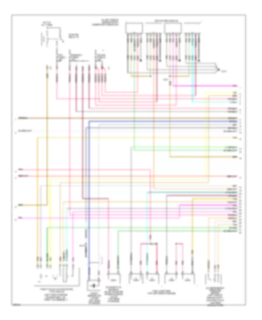
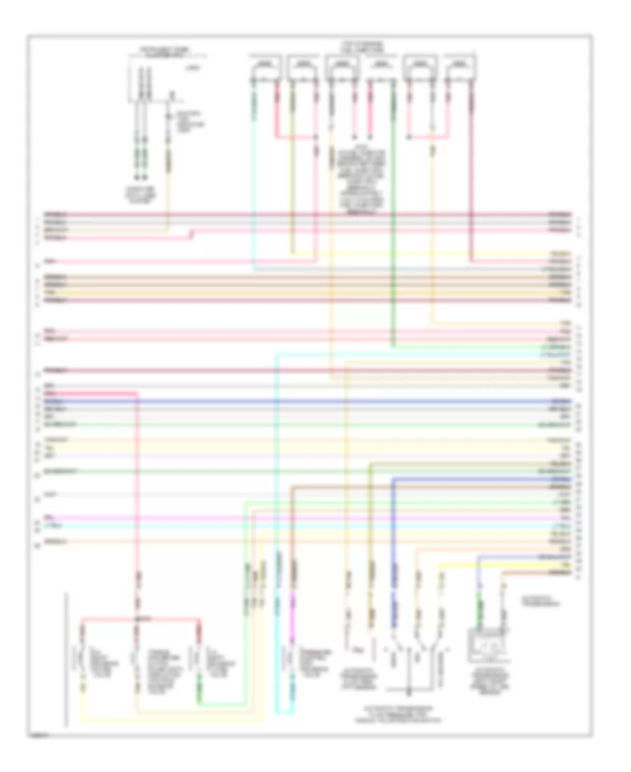
2.4L VIN B, Engine Performance Wiring Diagram (1 of 4) for Pontiac G6 GTP 2006
 https://portal-diagnostov.com/license.html
Automotive Electricians Portal FZCO
Automotive Electricians Portal FZCO
https://portal-diagnostov.com/license.html
https://portal-diagnostov.com/license.html
Automotive Electricians Portal FZCO
Automotive Electricians Portal FZCO
List of elements for 2.4L VIN B, Engine Performance Wiring Diagram (1 of 4) for Pontiac G6 GTP 2006:
- (in left side of engine compt) underhood fuse block
- 5v ref a
- 5v ref b
- A10
- Acc voltage
- Accelerator pedal position (app) sensor (attached to accelerator pedal)
- Accy
- Air conditioning system
- App sensor 1
- App sensor 2
- Bat
- Body control module (bcm) (under right side of center console, near dash)
- C10
- Cl rly ctrl
- Computer data lines system
- Cooling fans system
- Crank voltage
- Engine control module (ecm) (left rear of engine compt)
- Evap sol ctrl
- Evaporative emission (evap) canister vent solenoid valve (behind left side of rear fascia splash shield)
- Exterior lights system
- F pmp rly ctrl
- Fan rly ctrl
- Fuel level sens
- Fuel tank pressure (ftp) sensor (on top of fuel pump & sender assembly, part of fuel pump & sender assembly)
- G109 (left front of engine compt, on left rear side of core support, between g101 & g104)
- Gmlan data
- Hot at all times
- Ign
- Ign 1
- Inj fuse 44 10a
- Instrument panel cluster (ipc)
- Logic
- Low ref
- Malfunc- tion indicator lamp
- Mil ctrl
- Pcm fuse 13 10a
- Pcm ign 1 fuse 16 10a
- Pnk
- Press sens sig
- Rly coil ctrl
- Rly ctrl
- Run/ crank relay 32
- Starting/ charging system
- Starting/charging system
- Stop lp
- Tan
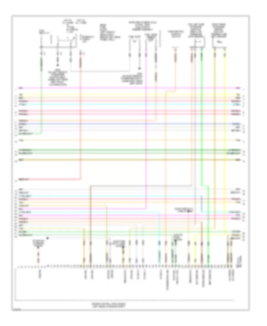
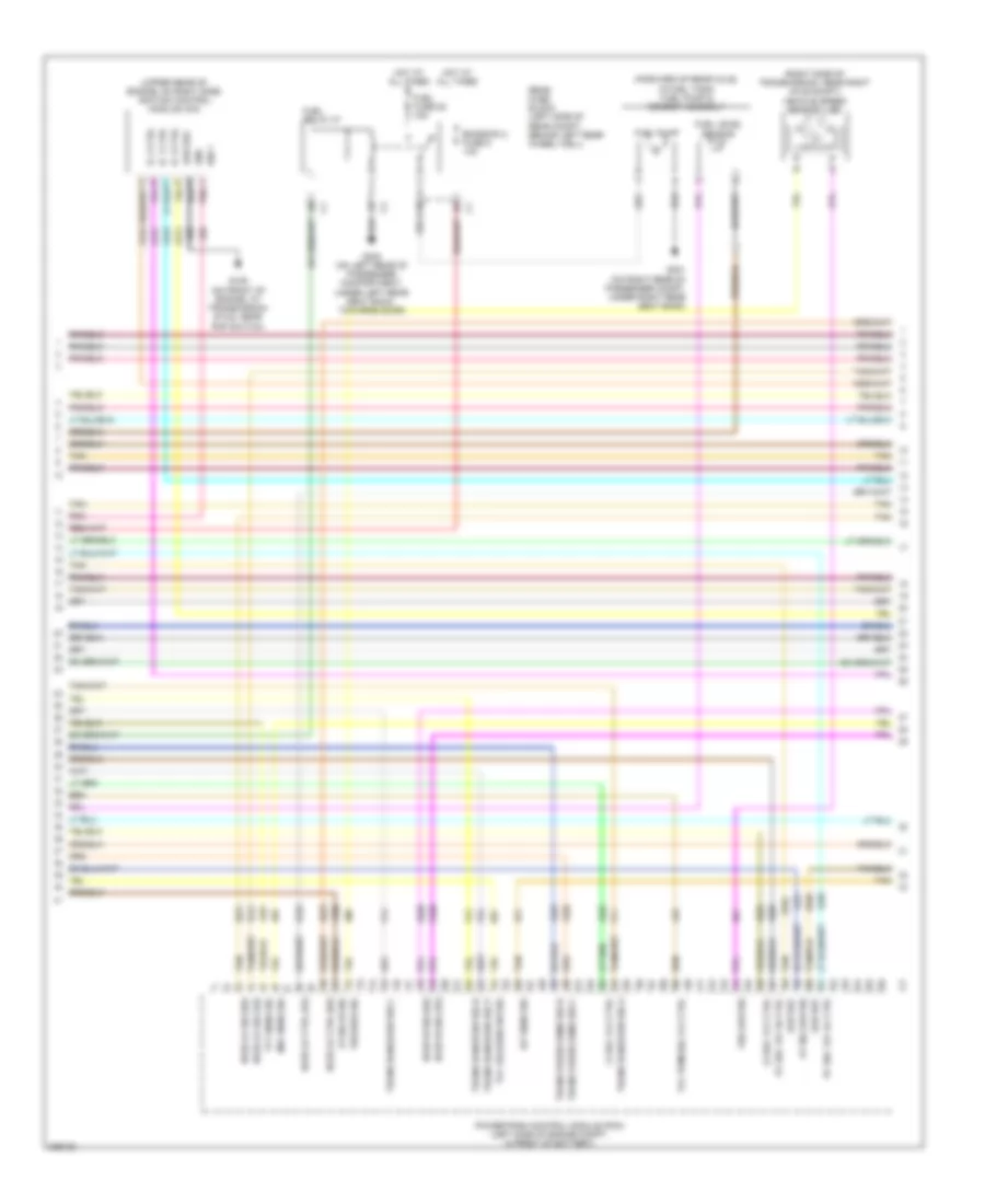
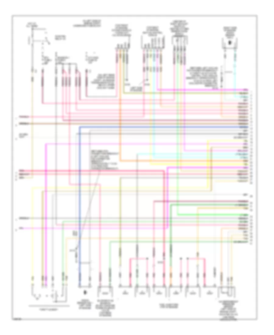
2.4L VIN B, Engine Performance Wiring Diagram (2 of 4) for Pontiac G6 GTP 2006
List of elements for 2.4L VIN B, Engine Performance Wiring Diagram (2 of 4) for Pontiac G6 GTP 2006:
- (in left side of engine compt) underhood fuse block
- (left side of engine compartment, on throttle assembly)
- A/c refrigerant pressure sensor (left side of engine compt,
- B11
- C11
- D11
- E11
- Emission 1 fuse 6 10a
- Etc fuse 2 15a
- Evaporative emission (evap) canister purge solenoid valve (top rear of engine)
- Fuel injectors (top left side of engine)
- G110
- Hot at all times
- Ign mod fuse 43 15a
- Ignition coil/module
- Knock sensor (ks) (lower left rear of engine)
- Mounted on a/c line near accumulator)
- Nca
- Pnk
- Pwr/trn relay 33
- S101
- S118
- S130
- Tan
- Throttle actuator control (tac) module
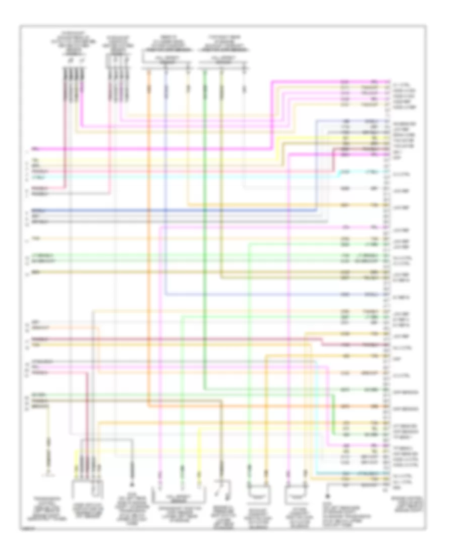
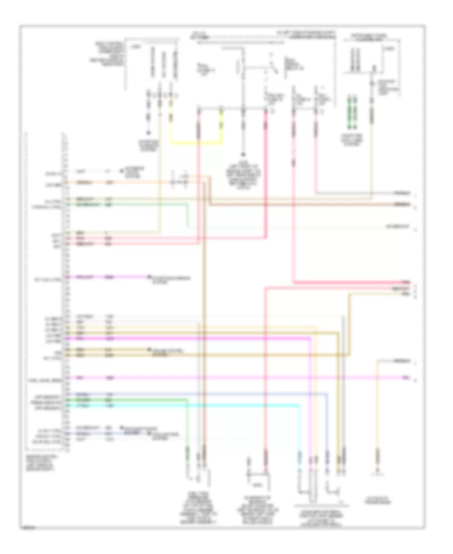
2.4L VIN B, Engine Performance Wiring Diagram (3 of 4) for Pontiac G6 GTP 2006
List of elements for 2.4L VIN B, Engine Performance Wiring Diagram (3 of 4) for Pontiac G6 GTP 2006:
- (forward of rear axle, in fuel tank) fuel pump & sender assembly
- (right rear of engine) engine coolant temperature (ect) sensor
- (top left side of engine) manifold absolute pressure (map) sensor
- 5v ref a
- 5v ref b
- A10
- C3 oil press
- Computer data lines system
- Cooling fans system
- Ect sens sig
- Emission 2 fuse 5 10a
- Engine control module (ecm) (left rear of engine compt)
- Evap sol
- Fan rly ctrl
- Fuel fuse 25 15a
- Fuel level sensor
- Fuel pump
- Fuel relay 37
- G301 (on right rear of passenger compt, under right rear seat back)
- G302 (on left rear of passenger compartment, under left rear seat back, towards door)
- Gen sig
- Gmlan data
- Hot at all times
- Low ref
- Map sens sig
- Not used) (67 to 73
- Oil press
- Park/neutral position switch
- Park/neutral sig
- Press sens sig
- Rear fuse block (left side of rear compt, behind left rear wheel well)
- Starting/ charging system
- Tan
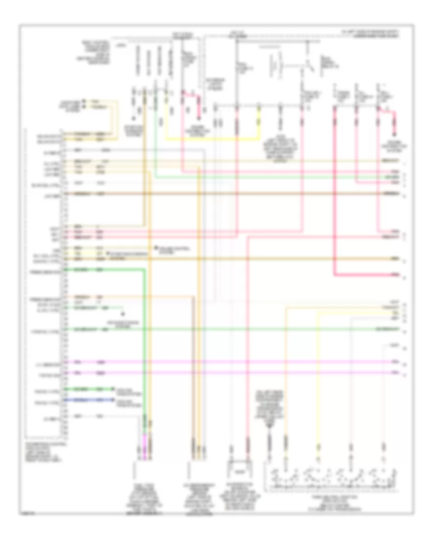
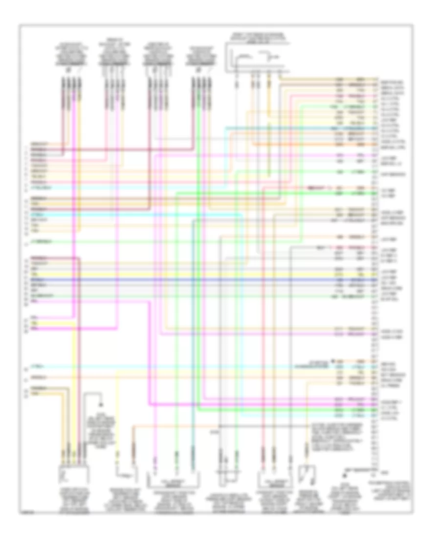
2.4L VIN B, Engine Performance Wiring Diagram (4 of 4) for Pontiac G6 GTP 2006
List of elements for 2.4L VIN B, Engine Performance Wiring Diagram (4 of 4) for Pontiac G6 GTP 2006:
- (in exhaust manifold) heated oxygen sensor (ho2s) 1
- (in exhaust, downstream of catalytic converter) heated oxygen sensor (ho2s) 2
- (rear of cylinder head) intake camshaft position (cmp) sensor
- (top right rear of engine) exhaust camshaft position (cmp) sensor
- 5v ref b
- 5v ref c
- Ckp sens sig
- Cmp
- Cmp
- Cmp sens sig
- Crankshaft position (ckp) sensor (lower left rear of engine)
- Drain wire
- Engine control module (ecm) (left rear of engine compt)
- Engine oil pressure (eop) switch (lower left rear of engine)
- Exhaust camshaft position (cmp) actuator solenoid
- G105 (on left rear side of engine compt, on engine transmission stud, below upper coolant hose)
- Gnd
- Hall effect sensor
- Ho2s hi sig
- Ho2s lo ctrl
- Ho2s lo ref
- Ho2s lo sig
- Ho2s ref
- Iat sens sig
- Ic 1 ctrl
- Ic 2 ctrl
- Ic 3 ctrl
- Ic 4 ctrl
- Ign 1
- Inj 1 ctrl
- Inj 2 ctrl
- Inj 3 ctrl
- Inj 4 ctrl
- Intake camshaft position (cmp) actuator solenoid
- Ks sens sig
- Low ref
- Maf sens sig
- Mass air flow (maf)/intake air temperature (iat) sensor
- Nca
- Tac motor
- Tan
- Tp sens 1
- Tp sens 2
- Transmission control module (tcm) (left rear of engine compt, near strut tower)
3.5L VIN 8
3.5L VIN 8, Engine Performance Wiring Diagram (1 of 5) for Pontiac G6 GTP 2006
List of elements for 3.5L VIN 8, Engine Performance Wiring Diagram (1 of 5) for Pontiac G6 GTP 2006:
- (in left side of engine compt) underhood fuse block
- (on left rear side of engine compartment, on engine transmission stud, below upper coolant hose) g105
- 5v ref a
- 5v ref b
- A/c refrigerant pressure sensor (left side of engine compt,
- Acc voltage
- Accy
- Air conditioning system
- B10
- Bat
- Body control module (bcm) (under right side of center console, near dash)
- C10
- Cl rly ctrl
- Computer data lines system
- Cooling fans system
- Crank voltage
- Cruise control system
- Evap sol ctrl
- Evaporative emission (evap) canister vent solenoid valve (behind left side of rear fascia splash shield)
- Exterior lights system
- F pmp rly ctrl
- Fan rly ctrl
- Fuel tank pressure (ftp) sensor (on top of fuel pump & sender assembly, part of fuel pump & sender assembly)
- G109 (left front of engine compt, on left rear side of core support, between g101 & g104)
- Gmlan data
- Hot at all times
- Hot in run or start
- Ign 1
- Ign 1 fuse 3 15a
- Inj fuse 44 10a
- Logic
- Low ref
- Lvl sens sig
- Main rly ctrl
- Mil ctrl
- Mounted on a/c line near accumulator)
- Park neutral position (pnp) switch (below master cylinder, on transmission)
- Pcm fuse 13 10a
- Pcm ign 1 fuse 16 10a
- Pnk
- Power distribution system
- Powertrain control module (pcm) (left side of engine compt, in front of battery)
- Press sens sig
- Rly coil ctrl
- Run/ crank fuse 2a
- Run/ crank relay 32
- Starting/ charging system
- Starting/charging system
- Stop lp sig
- Tan
- Tap enable sig
- Tap sw sig
- Trans fuse 4 10a
- Vss
3.5L VIN 8, Engine Performance Wiring Diagram (2 of 5) for Pontiac G6 GTP 2006
List of elements for 3.5L VIN 8, Engine Performance Wiring Diagram (2 of 5) for Pontiac G6 GTP 2006:
- (attached to accelerator pedal) accelerator pedal position (app) sensor
- (in engine harness, between pcm connectors breakout & left cooling fan connector breakout, approximately
- (in left side of engine compt) underhood fuse block
- (under center console, attached
- 5v ref
- 7.5 cm (3 in) from pcm connector breakout) s118
- App sens 1
- App sens 2
- B11
- Breakout, approximately 15 cm (6 in) from left cooling fan connector breakout)
- C11
- Control system
- Cruise
- D11
- E11
- Emission 1 fuse 6 10a
- Etc fuse 2 15a
- Evaporative emission (evap) canister purge solenoid (on intake manifold, near throttle body)
- G105 (on left rear side of engine compt, on engine transmission stud, below upper coolant hose)
- G303 (on left front of passenger compt, in back of left front kick panel)
- Gnd
- Hot at all times
- Ign 1
- Knock sensor (ks) 1 (front of engine, above starter)
- Knock sensor (ks) 2 (rear of engine, below exhaust manifold)
- Low ref
- Nca
- Pnk
- Pwr/trn relay 33
- S119 (in engine harness, between left cooling fan connector breakout & throttle actuator control (tac) module nca
- Serial data
- Stop lp sw
- Tan
- Tap up/ tap down switch
- Throttle actuator control (tac) module (left side of engine compartment, on throttle assembly)
- To a/t shift lever) a/t shift lock control solenoid
- Vss
3.5L VIN 8, Engine Performance Wiring Diagram (3 of 5) for Pontiac G6 GTP 2006
List of elements for 3.5L VIN 8, Engine Performance Wiring Diagram (3 of 5) for Pontiac G6 GTP 2006:
- (top of engine) fuel injectors
- 1-2 shift solenoid (1-2 ss) valve
- 2-3 shift solenoid (2-3 ss) valve
- 4 cm (1.6 in) from fuel injector 2 breakout)
- Automatic transmission
- Automatic transmission fluid pressure (tfp) manual valve position switch
- Automatic transmission fluid temp (tft) sensor
- Automatic transmission input shaft speed (at iss) sensor
- Computer data lines system
- Drive
- Gmlan data
- Ign
- Instrument panel cluster (ipc)
- Logic
- Malfunc- tion indicator lamp
- Pnk
- Pnk e
- Pressure control (pc) solenoid valve
- Red
- Red a
- Rev
- S103
- S130 (in fuel injector harness, on main branch between fuel injector 3 breakout & fuel injector 2 breakout, approximately
- Tan
- Tan m
- Tcc release
- Torque converter clutch pulse width modulation (tcc pwm) solenoid valve
3.5L VIN 8, Engine Performance Wiring Diagram (4 of 5) for Pontiac G6 GTP 2006
List of elements for 3.5L VIN 8, Engine Performance Wiring Diagram (4 of 5) for Pontiac G6 GTP 2006:
- (forward of rear axle, in fuel tank) fuel pump & sender assembly
- (right side of transmission, near right axle shaft) vehicle speed sensor (vss)
- (upper rear of engine, on right side) ignition control module (icm)
- 1-2 sol vlv ctrl
- 2-3 sol vlv ctrl
- A10
- At iss hi sig
- At iss low sig
- Emission 2 fuse 5 10a
- F pnk
- Fuel fuse 25 15a
- Fuel level sensor
- Fuel pump
- Fuel relay 37
- G106 (on front of engine, at transmission stud, near pnp switch)
- G301 (on right rear of passenger compt, under right rear seat back)
- G302 (on left rear of passenger compartment, under left rear seat back, towards door)
- Gnd
- Ho2s hi sig (1/2)
- Ho2s hi sig (2/2)
- Ho2s lo ctrl (1/2)
- Ho2s lo ctrl (2/2)
- Ho2s lo sig (1/2)
- Ho2s lo sig (2/2)
- Hot at all times
- Iat sens sig
- Ic 1 ctrl
- Ic 2 ctrl
- Ic 3 ctrl
- Ign 1
- Low ref
- Maf sens sig
- Pc sol vlv hi ctrl
- Pc sol vlv lo ctrl
- Pnk
- Powertrain control module (pcm) (left side of engine compt, in front of battery)
- Rear fuse block (left side of rear compt, behind left rear wheel well)
- Tan
- Tcc pwm sol vlv ctrl
- Tcc release sw sig
- Tft sens sig
- Trans press sens sig b
- Trans press sens sig c
- Trans range sw sig a
- Trans range sw sig b
- Trans range sw sig c
- Trans range sw sig p
- Vss high sig
- Vss low sig
3.5L VIN 8, Engine Performance Wiring Diagram (5 of 5) for Pontiac G6 GTP 2006
List of elements for 3.5L VIN 8, Engine Performance Wiring Diagram (5 of 5) for Pontiac G6 GTP 2006:
- (center of rear exhaust manifold) heated oxygen sensor (ho2s) bank 1 sensor 1
- (in exhaust, after catalytic converter) heated oxygen sensor (ho2s) bank 2 sensor 2
- (in fuel injector harness, on main branch between fuel injector 3 breakout & fuel injector 4 breakout, approximately
- (on exhaust manifold) heated oxygen sensor (ho2s) bank 2 sensor 1
- (rear of exhaust, after catalytic converter) heated oxygen sensor (ho2s) bank 1 sensor 2
- (right top rear of engine) exhaust gas recirculation (egr) valve
- 12v ref
- 3 cm (1.2 in) from fuel injector 3 breakout)
- 5v ref a
- A tan
- Camshaft position (cmp) sensor (in right side of engine compt, above timing chain cover)
- Cmp sens sig
- Crankshaft position (ckp) sensor (right side of engine, at end of crankshaft, behind harmonic balancer)
- Drain wire
- Ect sens sig
- Egr pos sig
- Egr sol ctrl
- Egr sol lo
- Eng spd sig
- Engine coolant temperature (ect) sensor (mounted in rear cylinder head, below coolant reservoir)
- Engine oil pressure (eop) switch (front center of engine, above starter)
- Evap sol
- G105 (on left rear side of engine compartment, on engine transmission stud, below upper coolant hose)
- G105 (on left rear side of engine compt, on engine transmission stud, below upper coolant hose)
- Gen sig
- Gnd
- Hall effect sensor
- Ho2s hi ref
- Ho2s lo ctrl
- Ho2s lo ref
- Ho2s lo sig
- Ho2s low
- Ho2s ref v
- Ic 1 ctrl
- Ic 2 ctrl
- Ic 3 ctrl
- Inj 1 ctrl
- Inj 2 ctrl
- Inj 3 ctrl
- Inj 4 ctrl
- Inj 5 ctrl
- Inj 6 ctrl
- Ks 1 sig
- Ks 2 sig
- Low ref
- Manifold absolute pressure (map) sensor (on top rear of engine, in upper intake manifold)
- Map sens sig
- Mass air flow (maf)/intake air temperature (iat) sensor (on top left side of engine, at air cleaner)
- Nca
- Oil press
- Powertrain control module (pcm) (left side of engine compartment, in front of battery)
- S106
- Serial data
- Starting/ charging system
- Tan
3.9L VIN 1
3.9L VIN 1, Engine Performance Wiring Diagram (1 of 4) for Pontiac G6 GTP 2006
List of elements for 3.9L VIN 1, Engine Performance Wiring Diagram (1 of 4) for Pontiac G6 GTP 2006:
- (in left side of engine compt) underhood fuse block
- 5v ref 2
- 5v ref a
- 5v ref b
- A10
- Acc voltage
- Accelerator pedal position (app) sensor (attached to accelerator pedal)
- Accy
- Air conditioning system
- App sensor 1
- App sensor 2
- Automatic transmission
- Bat
- Body control module (bcm) (under right side of center console, near dash)
- C10
- Cl rly ctrl
- Computer data lines system
- Cooling fans system
- Crank voltage
- Cruise control system
- Engine control module (ecm) (left rear of engine compt)
- Evap sol ctrl
- Evaporative emission (evap) canister vent solenoid valve (behind left side of rear fascia splash shield)
- Exterior lights system
- F pmp rly ctrl
- Fan rly ctrl
- Fuel level sens
- Fuel tank pressure (ftp) sensor (on top of fuel pump & sender assembly, part of fuel pump & sender assembly)
- G109 (left front of engine compt, on left rear side of core support, between g101 & g104)
- Gmlan data
- Hot at all times
- Ign
- Ign 1
- Ign 1 fuse 3 15a
- Inj fuse 44 10a
- Instrument panel cluster (ipc)
- Logic
- Low ref
- Malfunc- tion indicator lamp
- Mil ctrl
- Pcm fuse 13 10a
- Pcm ign 1 fuse 16 10a
- Pnk
- Press sens sig
- Rly coil ctrl
- Rly ctrl
- Run/ crank relay 32
- Starting/ charging system
- Starting/charging system
- Stop lp
- Tan
- Vss
3.9L VIN 1, Engine Performance Wiring Diagram (2 of 4) for Pontiac G6 GTP 2006
List of elements for 3.9L VIN 1, Engine Performance Wiring Diagram (2 of 4) for Pontiac G6 GTP 2006:
- (between left cooling fan connector breakout & throttle actuator control (tac) module breakout, approximately 15 cm (6 in) from left cooling fan connector breakout) s119
- (between pcm connectors breakout & left cooling fan connector breakout, approximately 7.5 cm (3 in) from pcm connector breakout)
- (center of right exhaust manifold) heated oxygen sensor (ho2s) bank 2 sensor 1
- (in left side of engine compt) underhood fuse block
- (left side of engine)
- (on left rear side of engine compt, on engine transmission stud, below upper coolant hose)
- (right side of engine) knock sensor (ks) 2
- (top front of engine) intake manifold tuning (imt) valve solenoid
- (top right of engine) ignition control module
- A/c refrigerant pressure sensor (left side of engine compt,
- B11
- C11
- Crtl d
- D11
- E11
- Emission 1 fuse 6 10a
- Etc fuse 2 15a
- Evaporative emission (evap) canister purge solenoid valve (top rear of engine)
- Fuel injectors (top of engine)
- G105
- G106
- Gnd b
- Gnd e
- Hot at all times
- Ic 1 crtl b
- Ic 2 crtl
- Ic 3 crtl c
- Ign a
- Ign f
- Imtv/dod fuse 45 10a
- Knock sensor (ks) 1 (left side of engine)
- Low ref d
- Mounted on a/c line near accumulator)
- Nca
- Pnk
- Pwr/trn relay 33
- S118
- S130
- Sig c
- Tan
- Throttle body
3.9L VIN 1, Engine Performance Wiring Diagram (3 of 4) for Pontiac G6 GTP 2006
List of elements for 3.9L VIN 1, Engine Performance Wiring Diagram (3 of 4) for Pontiac G6 GTP 2006:
- (68 to 73 not used)
- (forward of rear axle, in fuel tank) fuel pump & sender assembly
- (in engine oil pan) engine oil level sensor
- (m/t) clutch pedal position (cpp) sensor
- (rear of left cylinder head) engine coolant temperature (ect) sensor
- (top rear of engine) manifold absolute pressure (map) sensor
- 5v ref 1
- 5v ref a
- A10
- C3 vss low sig
- Computer data lines system
- Cooling fans system
- Cpp sens sig
- Ect sens sig
- Emission 2 fuse 5 10a
- Engine control module (ecm) (left rear of engine compt)
- Evap sol
- Fan rly ctrl
- Fuel fuse 25 15a
- Fuel level sensor
- Fuel pump
- Fuel relay 37
- G301 (on right rear of passenger compt, under right rear seat back)
- G302 (on left rear of passenger compartment, under left rear seat back, towards door)
- Gen sig
- Gmlan data
- Ho2s hi sig
- Ho2s lo ctrl
- Ho2s lo ref
- Ho2s lo sig
- Ho2s ref volt
- Hot at all times
- Imt valve crtl
- Imt valve sig
- Low ref
- Map sens sig
- Park/neutral sig
- Press sens sig
- Rear fuse block (left side of rear compt, behind left rear wheel well)
- Sig
- Starting/ charging system
- Tan
- Vss hi sig
3.9L VIN 1, Engine Performance Wiring Diagram (4 of 4) for Pontiac G6 GTP 2006
List of elements for 3.9L VIN 1, Engine Performance Wiring Diagram (4 of 4) for Pontiac G6 GTP 2006:
- (center of left exhaust manifold) heated oxygen sensor (ho2s) bank 1 sensor 1
- (in exhaust, after catalytic converter) heated oxygen sensor (ho2s) bank 2 sensor 2
- (lower left center of engine) engine oil pressure (eop) sensor
- (rear of exhaust, after catalytic converter) heated oxygen sensor (ho2s) bank 1 sensor 2
- (top front of engine) camshaft position (cmp) sensor
- 5v ref 1
- 5v ref a
- 5v ref b
- Camshaft position (cmp) actuator solenoid (front of engine)
- Cmp
- Cmp sens sig
- Crankshaft position (ckp) sensor (lower right rear of engine)
- Drain wire
- Engine control module (ecm) (left rear of engine compt)
- Engine oil pressure (eop) switch (lower left rear of engine)
- G105 (on left rear side of engine compt, on engine transmission stud, below upper coolant hose)
- Gnd
- Hall effect sensor
- Ho2s hi sig
- Ho2s lo ctrl
- Ho2s lo sig
- Iat sens sig
- Ic 1 ctrl
- Ic 2 ctrl
- Ic 3 ctrl
- Ign 1
- Inj 1 ctrl
- Inj 2 ctrl
- Inj 3 ctrl
- Inj 4 ctrl
- Inj 5 ctrl
- Inj 6 ctrl
- Low ref
- Maf sens sig
- Mass air flow (maf)/intake air temperature (iat) sensor (on top left side of engine, at air cleaner)
- Nca
- Sens 1 sig
- Sens 2 sig
- Sig
- Tac motor
- Tan
- Tp sens 1
- Tp sens 2
- Vehicle speed sensor (vss) (m/t) (on manual transmission)

 Čeština
 Dansk
Dansk Deutsch
 Ελληνικά
 English
 Español
 Suomi
Suomi Français
 Français
 עברית
עברית Hrvatski
 Magyar
 Italiano
 日本語
日本語 한국어
한국어 Nederlands
 Polski
 Português
 Português
 Română
 Русский
 Slovenčina
 Slovenščina
 Svenska
 Türkçe
 中文 (中国)