ENGINE PERFORMANCE
3.1L
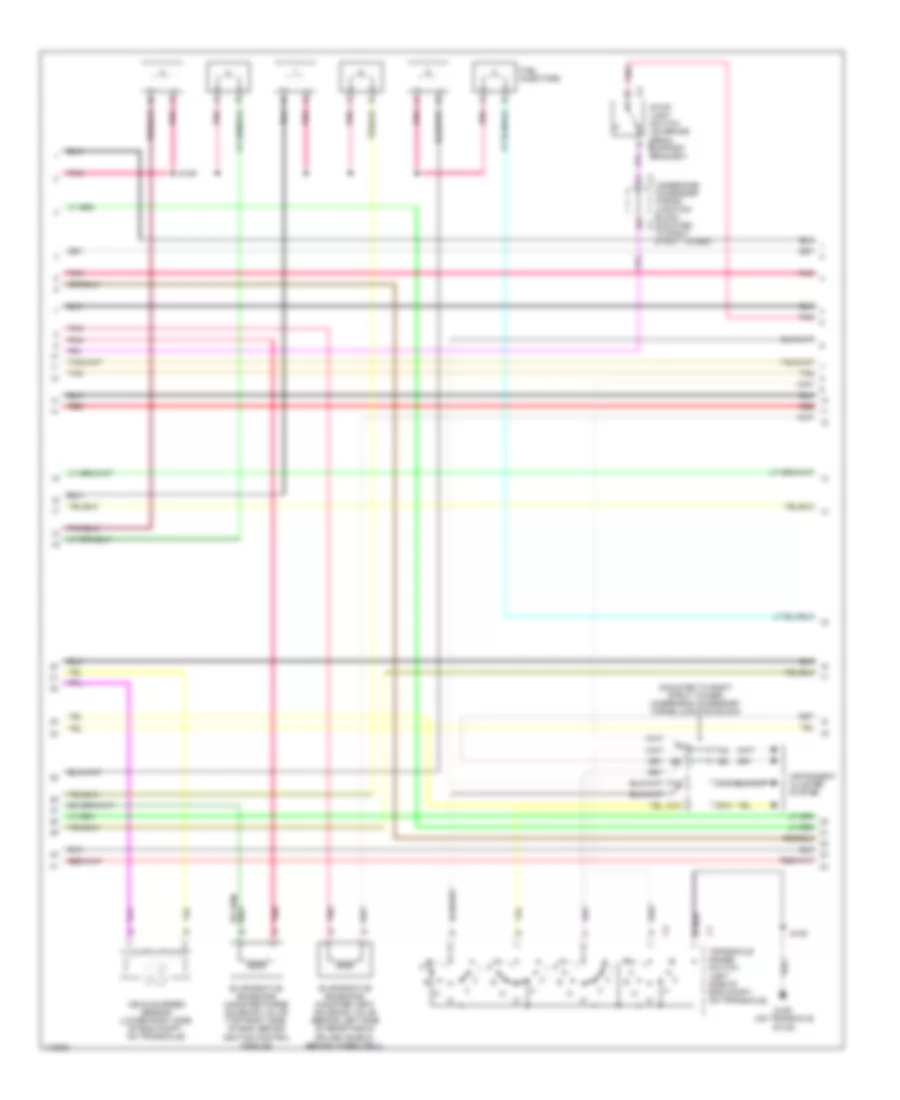
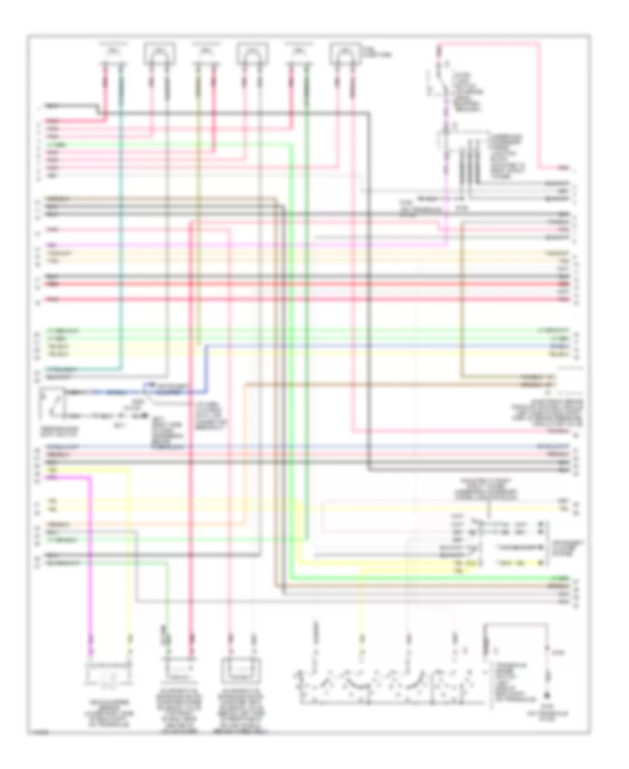
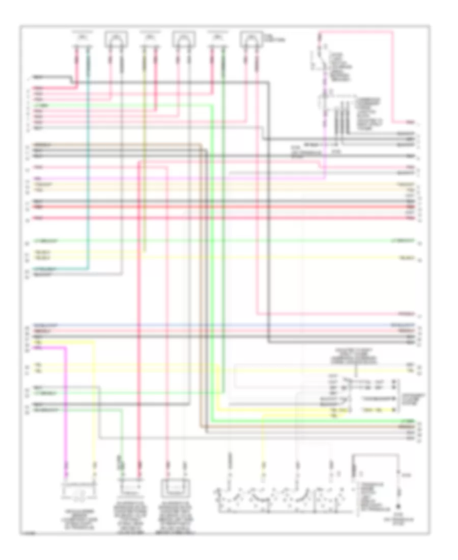
3.1L VIN M, Engine Performance Wiring Diagrams (1 of 4) for Pontiac Grand Prix GTP 1999
 https://portal-diagnostov.com/license.html
Automotive Electricians Portal FZCO
Automotive Electricians Portal FZCO
https://portal-diagnostov.com/license.html
https://portal-diagnostov.com/license.html
Automotive Electricians Portal FZCO
Automotive Electricians Portal FZCO
List of elements for 3.1L VIN M, Engine Performance Wiring Diagrams (1 of 4) for Pontiac Grand Prix GTP 1999:
- (eng harn, left side of eng compt 2 in from ebtcm breakout) s131
- (on transaxle stud)
- (pins 21-27 not used)
- (pins 39-42 not used)
- (pins 49-52 not used)
- (pins 62-63 not used)
- 1-2 ss valve control
- 2-3 ss valve control
- 3x ref high
- 3x ref low
- A12
- Anti-theft system
- Bypass control
- C10
- Camshaft position sensor (front of eng, below intake plenum)
- Canister vent fuse 10a
- Charge ind control
- Ckp sensor signal
- Cmp signal
- Cooling fan system
- Crankshaft position sensor (24x) (front of eng, behind harmonic balancer)
- Crankshaft position sensor (7x) (lower right side of of eng, below exhaust manifold)
- Cruise control system
- Cruise disable output
- D11
- Data link connector (under left side of dash, right of steering column)
- Ecm fuse 10a
- Ecm sense fuse 10a
- Egr sensor ground
- Egr val control (low)
- Elek ign fuse 15a
- Evap purge val drviver
- Fuel gauge siganl
- Fuel inj 1 driver
- Fuel inj 2 driver
- Fuel inj 3 driver
- Fuel inj 5 driver
- Fuel inj 6 driver
- Fuse block (behind right side of dash, in glove box opening)
- G129
- G129 (on transaxle stud)
- High speed fans control
- Ho2s 1 low
- Ho2s 2 low
- Hot at all times
- Hot coolant ind control
- Hot in run, bulb test or start
- Iac coil b high
- Iat sensor ground
- Ic control
- Ign1-uh fuse 15a
- Ignition
- Ignition control module (top right side of engine)
- Inj fuse 10a
- Instrument cluster system
- Knock sensor (left side of eng, above starter)
- Knock sensor signal
- Low speed fans control
- Maf sensor signal
- Map 5v ref
- Map/ect sensor ground
- Nca
- Pcm ground
- Pnk
- Pnk b
- Power (battery)
- Powertrain control module (left front side of eng compt, in air cleaner assembly)
- Red
- S106
- Serial data (class 2)
- Serial data (uart)
- Spark plugs
- Starting/ charging system
- Tan
- Tcc brake switch input
- Tft sensor ground
- Theft deter fuel enable
- Tp sensor ground
- Tr switch input b
- Underhood accessory wiring junction block (mounted to right strut tower)
- Vss high
- Vss low
- Vss output
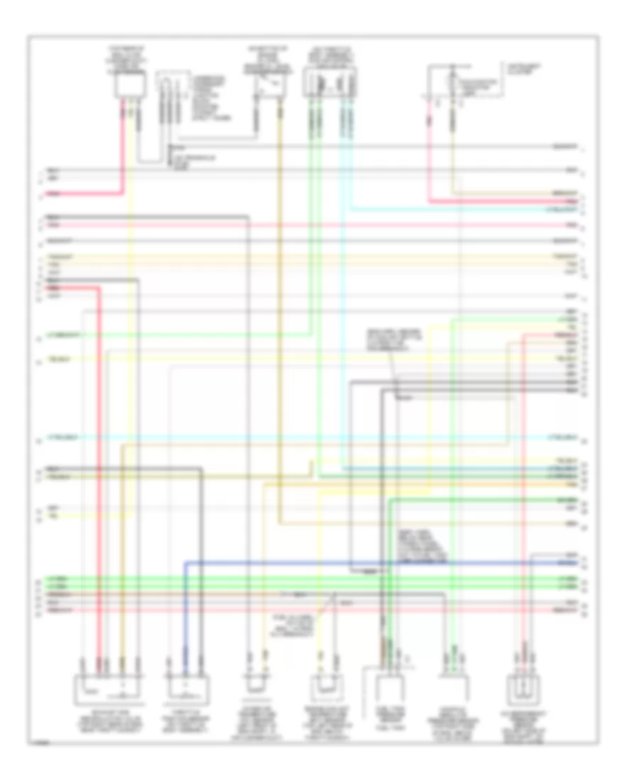
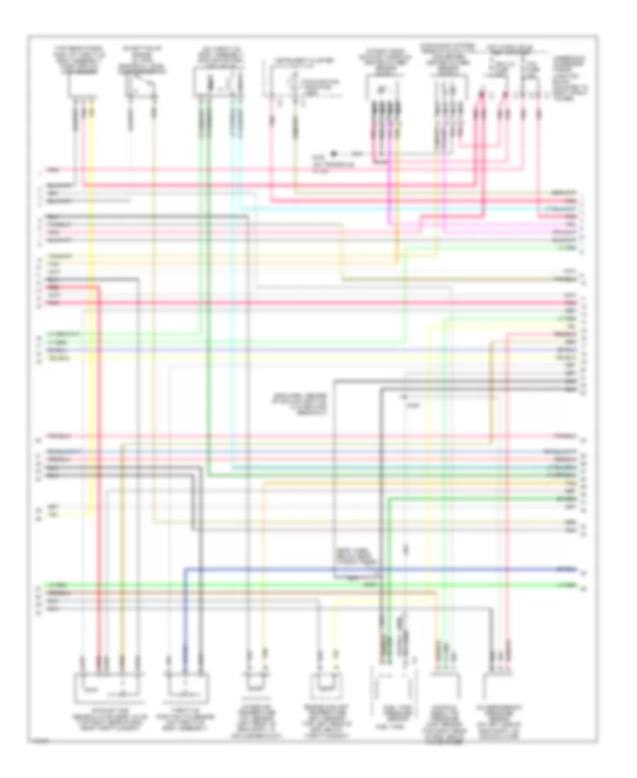
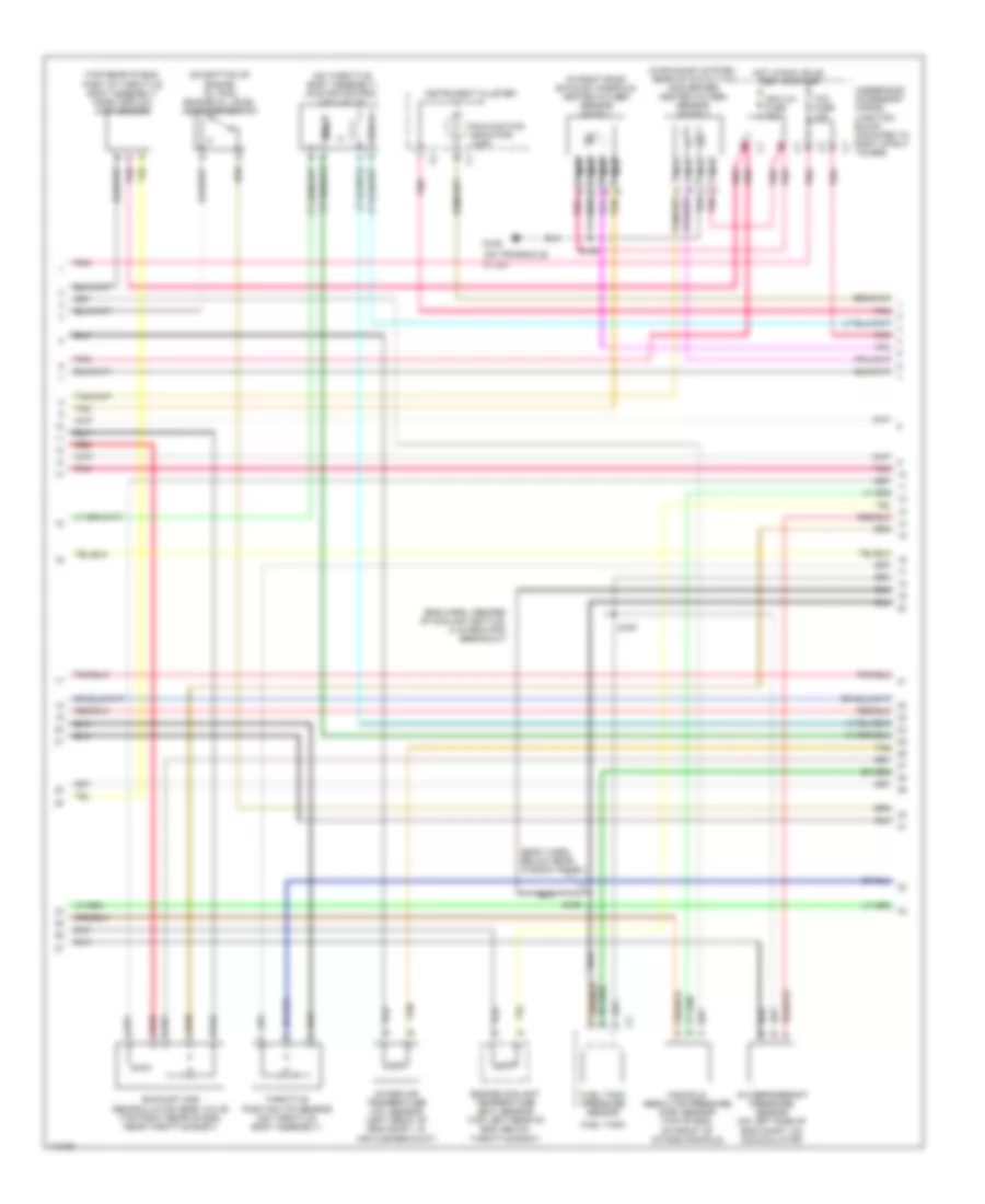
3.1L VIN M, Engine Performance Wiring Diagrams (2 of 4) for Pontiac Grand Prix GTP 1999
List of elements for 3.1L VIN M, Engine Performance Wiring Diagrams (2 of 4) for Pontiac Grand Prix GTP 1999:
- (mounted to right strut tower) underhood accessory wiring junction block
- A12
- Accessory wiring junction block (mounted to right strut tower)
- B10
- D10
- Evaporative emissions canister purge solenoid valve (top right side of eng, behind ignition control module)
- Evaporative emissions canister vent solenoid valve (behind left side of rear fascia splash shield, behind wheelwell)
- F12
- Fuel injectors
- G129 (on transaxle stud)
- Instrument cluster system
- Pnk
- Red
- S105
- S109
- Stop- light switch (on brake pedal support c2 bracket)
- Tan
- Transaxle range switch (left side of eng compt, on transaxle)
- Underhood c2
- Vehicle speed sensor (lower right side of eng compt, on transaxle)
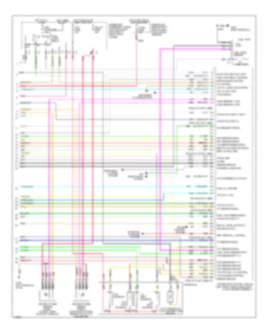
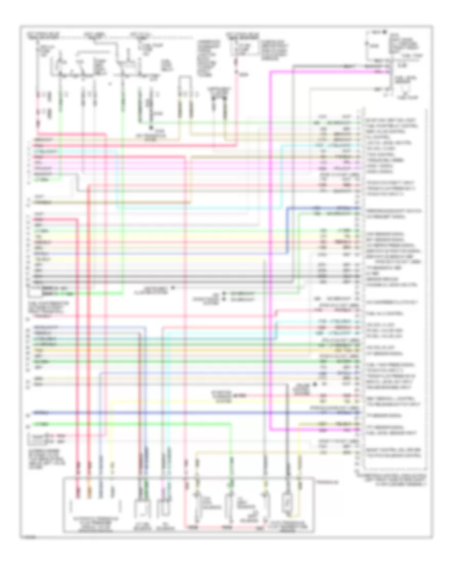
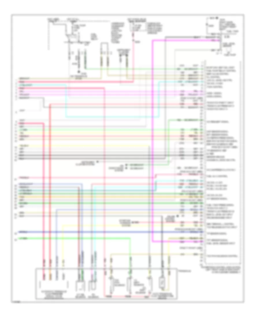
3.1L VIN M, Engine Performance Wiring Diagrams (3 of 4) for Pontiac Grand Prix GTP 1999
List of elements for 3.1L VIN M, Engine Performance Wiring Diagrams (3 of 4) for Pontiac Grand Prix GTP 1999:
- (body harn, below rear window panel, 4 in from break- out to fuel tank harn connector)
- (eng harn, inboard of coolant bottle, 2 in from the pcm breakout)
- (fuel inj harn, on top of eng, 1 in from inj 3 breakout)
- (on bottom of engine oil pan) engine oil level indicator switch
- (on throttle body assembly) idle air control (iac) valve
- (on transaxle stud) g129
- (top rear of eng, in air cleaner duct) mass air flow sensor
- A/c refrigerant pressure sensor (on left side of eng compt, on accumulator)
- Coil a
- Coil b
- Engine coolant temperature (ect) sensor (top left rear of eng, below throttle body)
- Exhaust gas recirculation valve (top right rear of eng, near throttle body)
- Fuel tank
- Fuel tank pressure sensor
- Instrument cluster
- Intake air temperature (iat) sensor (left front of eng compt, in air cleaner duct)
- Malfunction indicator lamp
- Manifold absolute pressure sensor (top right side of eng, above valve cover)
- Pnk
- Red
- S106
- S121
- S167
- S409
- Tan
- Throttle position sensor (on throttle body assembly)
- Underhood accessory wiring junction block (mounted to right strut tower)
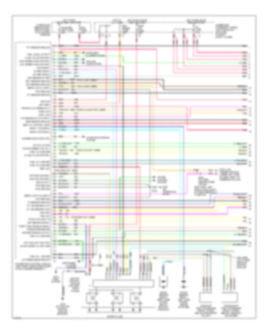
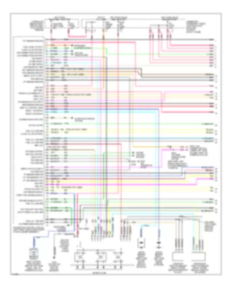
3.1L VIN M, Engine Performance Wiring Diagrams (4 of 4) for Pontiac Grand Prix GTP 1999
List of elements for 3.1L VIN M, Engine Performance Wiring Diagrams (4 of 4) for Pontiac Grand Prix GTP 1999:
- (not used) b4
- (pin 45-48 not used)
- (pin 51-54 not used)
- (pins 12-15 not used)
- (pins 19-21 not used)
- (pins 29,31,32 not used)
- (pins 62-65 not used)
- (pins 75-77 not used)
- (right door sill)
- 1-2 shift solenoid
- 2-3 shift solenoid
- 5v ref
- 87a
- A/c compress clutch rly
- A/c refrig press signal
- A/c request signal
- Air conditioning system
- Auto transaxle fluid temperature sensor
- Change oil soon ind
- Ckp sensor batt (+)
- Ckp sensor ground
- Cmp sensor batt (+)
- Cmp sensor ground
- Cruise control system
- Cruise status
- Ect sensor signal
- Egr pintle position signal
- Egr solenoid control
- Egr valve 5v ref
- Eng oil level switch in
- Evap can vent sol cont
- Fuel inj 4 driver
- Fuel level sensor
- Fuel level sensor input
- Fuel pump
- Fuel pump fuse 15a
- Fuel pump relay
- Fuel pump relay control
- Fuel tank
- Fuel tank press signal
- Fuse block (behind right side of dash, in glove box opening)
- G129 (on transaxle stud)
- G316
- Gen terminal l control
- Heated oxygen sensor (ho2s) 1 (in right bank exhaust manifold)
- Heated oxygen sensor (ho2s) 2 (in exhaust system, rear of catalytic converter)
- Ho2s sensor 1 high
- Ho2s sensor 2 high
- Hot at all times
- Hot in run, bulb test or start
- Hot in run, bulb test, or start
- I/p-ign fuse 10a
- Iac coil a low
- Iac coil b low
- Iac valve a high
- Iat sensor signal
- Ign1-uh fuse 15a
- Instrument cluster system
- Low oil level ind control
- Map sensor signal
- Mil control
- Nca
- Pnk
- Pnk e
- Powertrain control module (left front side of eng compt, in air cleaner assembly)
- Red
- S105
- S209
- S406
- Sensor ground
- Starting/ charging system
- Tach signal
- Tan
- Tcc fuse 10a
- Tcc pwm sol val control
- Tcc pwm solenoid
- Tcc solenoid
- Tcc solenoid control
- Tft sensor signal
- Tp sensor signal
- Tps 5v ref
- Tr switch input a
- Tr switch input c
- Tr switch parity input
- Transaxle
- Underhood accessory wiring junction block (mounted to right strut tower)
3.8L
3.8L VIN 1, Engine Performance Wiring Diagrams (1 of 4) for Pontiac Grand Prix GTP 1999
List of elements for 3.8L VIN 1, Engine Performance Wiring Diagrams (1 of 4) for Pontiac Grand Prix GTP 1999:
- (eng harn, left side of eng compt, 2 in from breakout to ebtcm)
- (ign harn, top of eng, near ign control module)
- (not used)
- (pin 11 not used)
- (pin 14 not used)
- (pins 21 & 23-27 not used)
- (pins 40-42 not used)
- (pins 49-52 not used)
- (pins 66-67 not used)
- 1-2 ss valve control
- 18x ref signal
- 2-3 ss valve control
- 3x ref signal
- A/c press sens ground
- A/t iss sensor high
- A/t iss sensor low
- A12
- Anti- theft system
- B12
- Bank 1 ks signal
- Bank 2 ks signal
- Battery
- Bypass control
- C10
- C12
- Camshaft position sensor (front of eng, above crankshaft pulley)
- Canister vent fuse 10a
- Charge indicator ctrl
- Cmp signal
- Cooling fans system
- Crankshaft position sensor (front of eng, behind harmonic balancer)
- Cruise control system
- Cruise disable output
- D11
- Data link connector (dlc) (under left side of dash, right of steering column)
- Ecm fuse 10a
- Ecm sense fuse 10a
- Ect sensor ground
- Egr sensor ground
- Egr val control (gnd)
- Elek ign fuse 15a
- Evap purge val drviver
- F/pump speed ctrl rly
- Fuel inj 1 driver
- Fuel inj 2 driver
- Fuel inj 4 driver
- Fuel inj 5 driver
- Fuel inj 6 driver
- Fuel level output
- Fuse block (behind right side of dash, in glove box opening)
- G120 (on ignition control module bracket)
- G129 (on transaxle stud)
- High speed fans control
- Hos1 low
- Hos2 low
- Hot at all times
- Hot coolant ind ctrl
- Hot in run bulb test, or start
- Hot in run, bulb test or start
- Iac coil b high
- Iat sensor ground
- Ignition
- Ignition control
- Ignition control module (top left front of eng)
- Inj fuse 10a
- Instrument cluster system
- Knock sensor bank 1 (left side of eng, above starter)
- Knock sensor bank 2 (right side of eng, below exhaust manifold)
- Low speed fans control
- Maf sensor signal
- Map sensor 5v ref
- Map sensor ground
- Pcm ground
- Pnk
- Pnk p
- Powertrain control module (left front side of eng compt, in air cleaner assembly)
- Red
- Ref low
- S106
- S131
- S144
- S145
- S218 (i/p harn, near blower motor)
- Serial data (class ii)
- Serial data (uart)
- Spark plugs
- Starting/charging system
- Tan
- Tcc brake switch input
- Tft sensor ground
- Theft fuel enable signal
- Torque requested
- Tp sensor ground
- Tr switch input b
- Trans fluid press sw a
- Underhood accessory wiring junction block (mounted to right strut tower)
- Vss high
- Vss low
- Vss output
3.8L VIN 1, Engine Performance Wiring Diagrams (2 of 4) for Pontiac Grand Prix GTP 1999
List of elements for 3.8L VIN 1, Engine Performance Wiring Diagrams (2 of 4) for Pontiac Grand Prix GTP 1999:
- (i/p harn, 12 in from data link connector breakout)
- (mounted to right strut tower) underhood accessory wiring junction block
- (on transaxle stud)
- (w/u40)
- A12
- B10
- D10
- Electronic brake traction control module (left side of eng compt, part of brake pressure, modulator valve)
- Evaporative emissions (evap) canister purge solenoid valve (top right of eng, near center of valve cover)
- Evaporative emissions (evap) canister vent solenoid valve (behind left side of rear fascia splash shield, behind wheelwell)
- F12
- Fuel injectors
- G129
- G201 (right side of dash crossbeam, behind fuse block)
- Instrument cluster
- Instrument cluster system
- Nca
- Performance shift switch
- Pnk
- Red
- S105
- S106
- S211
- S236
- Stop- light switch (on brake pedal support c2 bracket)
- Tan
- Transaxle range switch (left side of eng compt, on transaxle)
- Underhood accessory wiring junction block (mounted to right strut tower)
- Vehicle speed sensor (lower right side of eng compt, on transaxle)
3.8L VIN 1, Engine Performance Wiring Diagrams (3 of 4) for Pontiac Grand Prix GTP 1999
List of elements for 3.8L VIN 1, Engine Performance Wiring Diagrams (3 of 4) for Pontiac Grand Prix GTP 1999:
- (1999)
- (2000)
- (body harn, below rear window panel)
- (eng harn, inboard of coolant bottle, 2 in from pcm breakout)
- (in exhaust system, rear of catalytic converter) heated oxygen sensor (ho2s) 2
- (in right bank exhaust manifold) heated oxygen sensor (ho2s) 1
- (on bottom of engine oil pan) engine oil level indicator switch
- (on throttle body assembly) idle air control (iac) valve
- (on transaxle stud)
- (top rear of eng, part of throttle body assembly) mass airflow (maf) sensor
- A tan
- A/c refrigerant pressure sensor (on left side of eng compt, on accumulator)
- Coil a
- Coil b
- D pnk
- Engine coolant temperature (ect) sensor (top left rear of eng, below throttle body)
- Exhaust gas recirculation (egr) valve (top right rear of eng, near throttle body)
- Fuel tank
- Fuel tank pressure sensor
- G129
- Hot in run, bulb test or start
- Ign1-uh fuse 15a
- Instrument cluster
- Intake air temperature (iat) sensor (left front of eng compt, in air cleaner duct)
- Malfunction indicator lamp
- Manifold absolute pressure (map) sensor (top right rear of eng, above valve cover)
- Nca
- Pnk
- Red
- S105
- S167
- S409
- Tan
- Tcc fuse 10a
- Throttle position (tp) sensor (on throttle body assembly)
- Underhood accessory wiring junction block (mounted to right strut tower)
3.8L VIN 1, Engine Performance Wiring Diagrams (4 of 4) for Pontiac Grand Prix GTP 1999
List of elements for 3.8L VIN 1, Engine Performance Wiring Diagrams (4 of 4) for Pontiac Grand Prix GTP 1999:
- (1999)
- (2000)
- (not used)
- (on transaxle stud)
- (pin 47-48 not used)
- (pins 12-15 not used)
- (pins 29,31-32 not used)
- (pins 40-41 not used)
- (pins 51-54 not used)
- (pins 62 & 64-65 not used)
- (pins 71-76 not used)
- (right door sill, forward of right front seat)
- 1-2 shift solenoid
- 2-3 shift solenoid
- 5v ref
- 87a
- A auto transaxle fluid temperature sensor
- A/c compress clutch rly
- A/c refrig press signal
- A/c request signal
- A/t iss solenoid
- Air conditioning system
- Automatic transaxle fluid pressure manual valve position switch
- Boost control sol driver
- Change oil soon ind ctrl
- Cruise control system
- Cruise engaged input
- Ect sensor signal
- Egr pintle position signal
- Egr pintle sens 5v ref
- Egr valve control
- Eng oil level sw input
- Evap can vent sol cont
- F/pmp spd cont relay
- Fuel inj 3 control
- Fuel level sensor
- Fuel level sensor input
- Fuel pump
- Fuel pump fuse 15a
- Fuel pump relay
- Fuel pump relay control
- Fuel pump resistor (outside of right front frame rail)
- Fuel tank
- Fuel tank press signal
- Fuse block (behind right side of dash, in glove box opening)
- G129
- G316
- Gen terminal l control
- Ho2s 1 signal
- Ho2s 2 signal
- Hot at all times
- Hot in run, bulb test, or start
- I/p ign fuse 10a
- Iac coil a high
- Iac coil a low
- Iac coil b low
- Iat sensor signal
- Ign1-uh fuse 15a
- Instrument cluster system
- Low oil level ind ctrl
- Map sensor signal
- Mil control
- Nca
- Pc sol valve high
- Pc sol valve low
- Pc solenoid
- Performance shift switch
- Pnk
- Pnk e
- Powertrain control module (pcm) (left front side of eng compt, in air cleaner assembly)
- Red
- S106
- S209
- S406
- Sensor ground
- Starting/ charging system
- Supercharger by-pass valve (top rear of eng, above left valve cover)
- Tach control
- Tan
- Tcc pwm solenoid
- Tcc pwm solenoid control
- Tcc release switch input
- Tft sensor signal
- Torque delivered
- Tp sensor 5v ref
- Tp sensor signal
- Tr switch input a
- Tr switch input c
- Tr switch parity input
- Trans fluid press sw b
- Trans fluid press sw c
- Transaxle
- Underhood accessory wiring junction block (mounted to right strut tower)
3.8L VIN K, Engine Performance Wiring Diagrams (1 of 4) for Pontiac Grand Prix GTP 1999
List of elements for 3.8L VIN K, Engine Performance Wiring Diagrams (1 of 4) for Pontiac Grand Prix GTP 1999:
- (eng harn, left side of eng compt, 2 in from breakout to ebtcm)
- (ign harn, top of eng, near ign control module)
- (not used)
- (pin 11 not used)
- (pin 14 not used)
- (pins 21 & 23-27 not used)
- (pins 40-42 not used)
- (pins 49-52 not used)
- (pins 66-67 not used)
- 1-2 ss valve control
- 18x ref signal
- 2-3 ss valve control
- 3x ref signal
- A/c press sens ground
- A/t iss sensor high
- A/t iss sensor low
- A12
- B12
- Bank 1 ks signal
- Bank 2 ks signal
- Battery
- Body control module (bcm) (behind left side dash, left of steering column)
- Bypass control
- C10
- C12
- Camshaft position sensor (front of eng, above crankshaft pulley)
- Canister vent fuse 10a
- Charge indicator ctrl
- Cmp signal
- Cooling fans system
- Crankshaft position sensor (front of eng, behind harmonic balancer)
- Cruise control system
- Cruise disable output
- D11
- Data link connector (dlc) (under left side of dash, right of steering column)
- Ecm fuse 10a
- Ecm sense fuse 10a
- Ect sensor ground
- Egr sensor ground
- Egr val control (gnd)
- Elek ign fuse 15a
- Evap purge val drviver
- Fuel inj 1 driver
- Fuel inj 2 driver
- Fuel inj 4 driver
- Fuel inj 5 driver
- Fuel inj 6 driver
- Fuel level output
- Fuse block (behind right side of dash, in glove box opening)
- G120 (on ignition control module bracket)
- G129 (on transaxle stud)
- High speed fans control
- Hos1 low
- Hos2 low
- Hot at all times
- Hot coolant ind ctrl
- Hot in run bulb test, or start
- Hot in run, bulb test or start
- Iac coil b high
- Iat sensor ground
- Ignition
- Ignition control
- Ignition control module (top left front of eng)
- Inj fuse 10a
- Instrument cluster system
- Knock sensor bank 1 (left side of eng, above starter)
- Knock sensor bank 2 (right side of eng, below exhaust manifold)
- Low speed fans control
- Maf sensor signal
- Map sensor 5v ref
- Map sensor ground
- Pcm ground
- Pnk
- Pnk p
- Powertrain control module (left front side of eng compt, in air cleaner assembly)
- Red
- Ref low
- S106
- S131
- S144
- S145
- S218 (i/p harn, near blower motor)
- Serial data (class ii)
- Serial data (uart)
- Spark plugs
- Starting/charging system
- Tan
- Tcc brake switch input
- Tft sensor ground
- Theft fuel enable signal
- Tp sensor ground
- Tr switch input b
- Trans fluid press sw a
- Underhood accessory wiring junction block (mounted to right strut tower)
- Vss high
- Vss low
- Vss output
3.8L VIN K, Engine Performance Wiring Diagrams (2 of 4) for Pontiac Grand Prix GTP 1999
List of elements for 3.8L VIN K, Engine Performance Wiring Diagrams (2 of 4) for Pontiac Grand Prix GTP 1999:
- (mounted to right strut tower) underhood accessory wiring junction block)
- (on transaxle stud)
- A12
- B10
- D10
- Evaporative emissions (evap) canister purge solenoid valve (top right of eng, near center of valve cover)
- Evaporative emissions (evap) canister vent solenoid valve (behind left side of rear fascia splash shield, behind wheelwell)
- F12
- Fuel injectors
- G129
- Instrument cluster system
- Pnk
- Red
- S105
- S106
- Stop- light switch (on brake pedal support c2 bracket)
- Tan
- Transaxle range switch (left side of eng compt, on transaxle)
- Underhood accessory wiring junction block (mounted to right strut tower)
- Vehicle speed sensor (lower right side of eng compt, on transaxle)
3.8L VIN K, Engine Performance Wiring Diagrams (3 of 4) for Pontiac Grand Prix GTP 1999
List of elements for 3.8L VIN K, Engine Performance Wiring Diagrams (3 of 4) for Pontiac Grand Prix GTP 1999:
- (body harn, below rear window panel)
- (eng harn, inboard of coolant bottle, 2 in from pcm breakout)
- (in exhaust system, rear of catalytic converter) heated oxygen sensor (ho2s) 2
- (in right bank exhaust manifold) heated oxygen sensor (ho2s) 1
- (on bottom of engine oil pan) engine oil level indicator switch
- (on throttle body assembly) idle air control (iac) valve
- (on transaxle stud)
- (top rear of eng, part of throttle body assembly) mass airflow (maf) sensor
- A tan
- A/c refrigerant pressure sensor (on left side of eng compt, on accumulator)
- Coil a
- Coil b
- D pnk
- Engine coolant temperature (ect) sensor (top left rear of eng, below throttle body)
- Exhaust gas recirculation (egr) valve (top right rear of eng, near throttle body)
- Fuel tank
- Fuel tank pressure sensor
- G129
- Hot in run, bulb test or start
- Ign1-uh fuse 15a
- Instrument cluster
- Intake air temperature (iat) sensor (left front of eng compt, in air cleaner duct)
- Malfunction indicator lamp
- Manifold absolute pressure (map) sensor (top of eng, on front of intake manifold)
- Nca
- Pnk
- Red
- S105
- S167
- S409
- Tan
- Tcc fuse 10a
- Throttle position (tp) sensor (on throttle body assembly)
- Underhood accessory wiring junction block (mounted to right strut tower)
3.8L VIN K, Engine Performance Wiring Diagrams (4 of 4) for Pontiac Grand Prix GTP 1999
List of elements for 3.8L VIN K, Engine Performance Wiring Diagrams (4 of 4) for Pontiac Grand Prix GTP 1999:
- (not used)
- (on transaxle stud)
- (pin 47-48 not used)
- (pins 12-15 not used)
- (pins 29,31-32 not used)
- (pins 40-41 not used)
- (pins 51-54 not used)
- (pins 62 & 64-65 not used)
- (pins 71-76 not used)
- (right door sill, forward of right front seat)
- 1-2 shift solenoid
- 2-3 shift solenoid
- 5v ref
- 87a
- A auto transaxle fluid temperature sensor
- A/c compress clutch rly
- A/c refrig press signal
- A/c request signal
- A/t iss solenoid
- Air conditioning system
- Automatic transaxle fluid pressure manual valve position switch
- Change oil soon ind ctrl
- Cruise control system
- Cruise engaged input
- Ect sensor signal
- Egr pintle position signal
- Egr pintle sens 5v ref
- Egr valve control
- Eng oil level sw input
- Evap can vent sol cont
- Fuel inj 3 control
- Fuel level sensor
- Fuel level sensor input
- Fuel pump
- Fuel pump fuse 15a
- Fuel pump relay
- Fuel pump relay control
- Fuel tank
- Fuel tank press signal
- Fuse block (behind right side of dash, in glove box opening)
- G129
- G316
- Gen terminal l control
- Ho2s 1 signal
- Ho2s 2 signal
- Hot at all times
- Hot in run, bulb test, or start
- I/p ign fuse 10a
- Iac coil a high
- Iac coil a low
- Iac coil b low
- Iat sensor signal
- Instrument cluster system
- Low oil level ind ctrl
- Map sensor signal
- Mil control
- Pc sol valve high
- Pc sol valve low
- Pc solenoid
- Pnk
- Pnk e
- Powertrain control module (pcm) (left front side of eng compt, in air cleaner assembly)
- Red
- S106
- S209
- S406
- Sensor ground
- Starting/ charging system
- Tach control
- Tan
- Tcc pwm solenoid
- Tcc pwm solenoid control
- Tcc release switch input
- Tft sensor signal
- Tp sensor 5v ref
- Tp sensor signal
- Tr switch input a
- Tr switch input c
- Tr switch parity input
- Trans fluid press sw b
- Trans fluid press sw c
- Transaxle
- Underhood accessory wiring junction block (mounted to right strut tower)

 Čeština
 Dansk
Dansk Deutsch
 Ελληνικά
 English
 Español
 Suomi
Suomi Français
 Français
 עברית
עברית Hrvatski
 Magyar
 Italiano
 日本語
日本語 한국어
한국어 Nederlands
 Polski
 Português
 Português
 Română
 Русский
 Slovenčina
 Slovenščina
 Svenska
 Türkçe
 中文 (中国)