ENGINE PERFORMANCE
2.2L VIN F
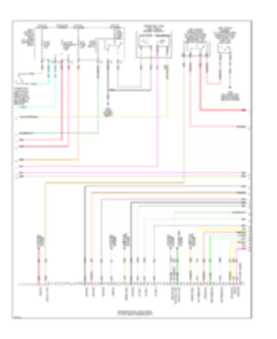
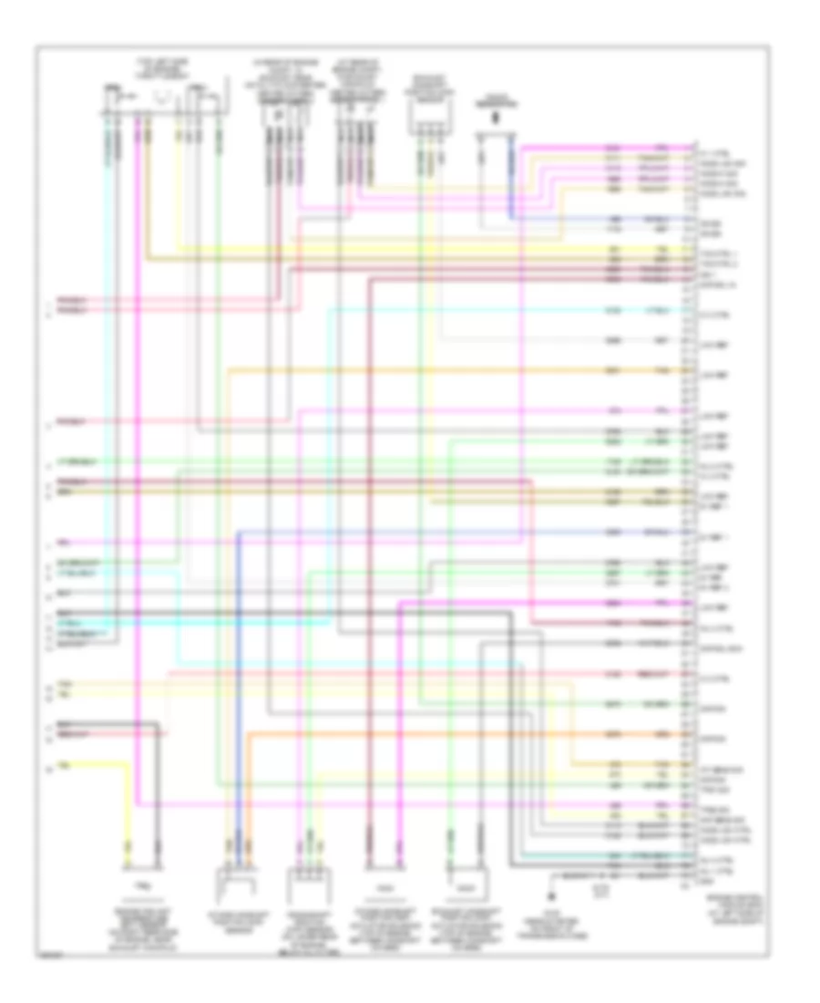
2.2L VIN F, Engine Performance Wiring Diagram (1 of 4) for Saturn Ion 3 2007
 https://portal-diagnostov.com/license.html
Automotive Electricians Portal FZCO
Automotive Electricians Portal FZCO
https://portal-diagnostov.com/license.html
https://portal-diagnostov.com/license.html
Automotive Electricians Portal FZCO
Automotive Electricians Portal FZCO
List of elements for 2.2L VIN F, Engine Performance Wiring Diagram (1 of 4) for Saturn Ion 3 2007:
- (at lower center of dash)
- (in body
- 5v ref 1
- 5v ref 2
- A/c clutch rly
- A10
- Acc
- Acc volt
- Accelerator pedal position (app) sensor (below left side of dash)
- Accessory vol
- Air conditioning system
- Air sol ctrl
- App sens 1 sig
- App sens 2 sig
- App sensor 1
- App sensor 2
- Battery
- Battery +
- Body control module (bcm)
- Class 2 data
- Clutch pedal position (cpp) switch (m/t) (below left side of dash)
- Computer data lines system
- Cpp sw sig
- Cruise control system
- Cruise ctrl
- Data class 2
- E10
- Ecm/ tcm fuse 1 10a
- Electronic brake control module (ebcm) (if equipped) (at left side of engine compt)
- Engine control module (ecm) (at left side of engine compt)
- Evap sol ctrl
- Evaporative emission (evap) canister vent solenoid (under rear of vehicle, behind fuel tank)
- Fuel pmp rly
- Fuel pres sig
- Fuel sens sig
- Fuel tank pressure (ftp) sensor (under right rear of vehicle, on evap canister)
- G101 (behind left front headlight)
- Harness, left rear side of engine compt) s104
- Hot at all times
- Ign 1
- Ignition switch
- Instrument panel cluster (ipc)
- Ip/ ign sw fuse 2a
- Logic
- Low ref
- Lower stop lamp switch (below left side of dash, attached to brake pedal bracket)
- Malfunc- tion indicator lamp
- Mil ctrl
- Off
- Pnk
- Pwr rly ctrl
- Rly coil ctrl
- Run
- Run/ crank relay 28
- Run/crank fuse 38 30a k1
- Run/crnk volt
- S101
- Serial data
- Start
- Starting/ charging systtem
- Stop lp sw sig
- Tan
- Tcc sw sig
- Trans 2 fuse 13 10a
- Transmissions system
- Underhood fuse block (left rear side of engine compt)
- Up-shift ind
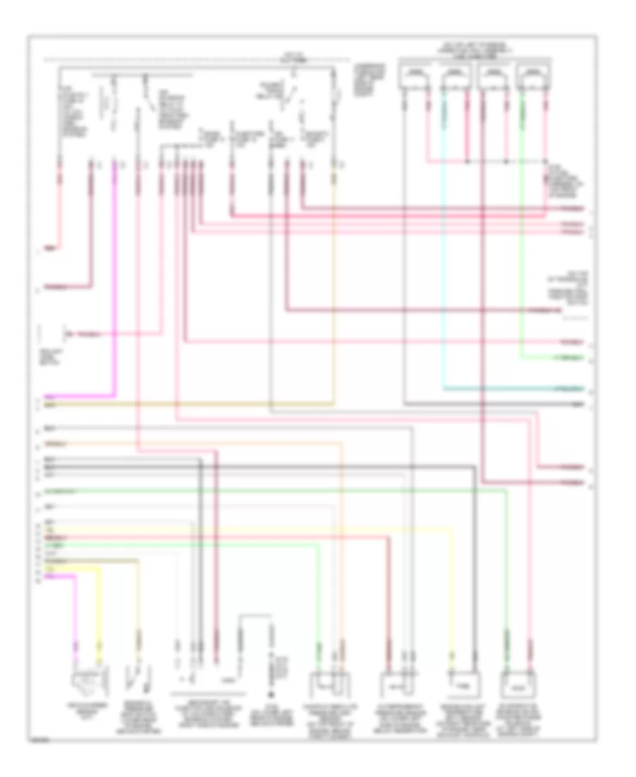
2.2L VIN F, Engine Performance Wiring Diagram (2 of 4) for Saturn Ion 3 2007
List of elements for 2.2L VIN F, Engine Performance Wiring Diagram (2 of 4) for Saturn Ion 3 2007:
- (68 to 73 not used)
- (inside fuel tank) fuel pump & sender assembly
- (left side of engine compt) (w/ california pzev emission system) secondary air injection (air) relay
- (left side of engine) (w/ california pzev emission system) secondary air injection (air) pump
- 5v ref 1
- 5v ref 2
- Air press sig
- Air rly ctrl
- Bcm fuse 15a
- Body control module (bcm) (at lower center of dash)
- Clutch/ brake/aos fuse 7.5a
- Computer data lines system
- Cooling fans system
- Driver's seat)
- Ect sens sig
- Engine control module (ecm) (at left side of engine compt)
- Evap sol ctrl
- Fan rly ctrl
- Fuel pump
- Fuel pump fuse 15a
- Fuel pump relay
- Fuel sensor
- G105 (on lower left rear of engine, above starter)
- G301 (under
- Gen sig
- Hot at all times
- Hot in acc or run
- Low ref
- Map sens sig
- Nca
- Oil sw sig
- Pnk
- Pnp sw sig
- Red
- Refrig sig
- S351
- Serial bus+
- Serial bus-
- Starting/
- Starting/ charging system
- Stop fuse 15a
- System charging
- System charging starting/
- System data lines computer
- Tan
- Upper stop lamp switch (below left side of dash, attached to brake pedal bracket)
- Vss hi
- Vss low
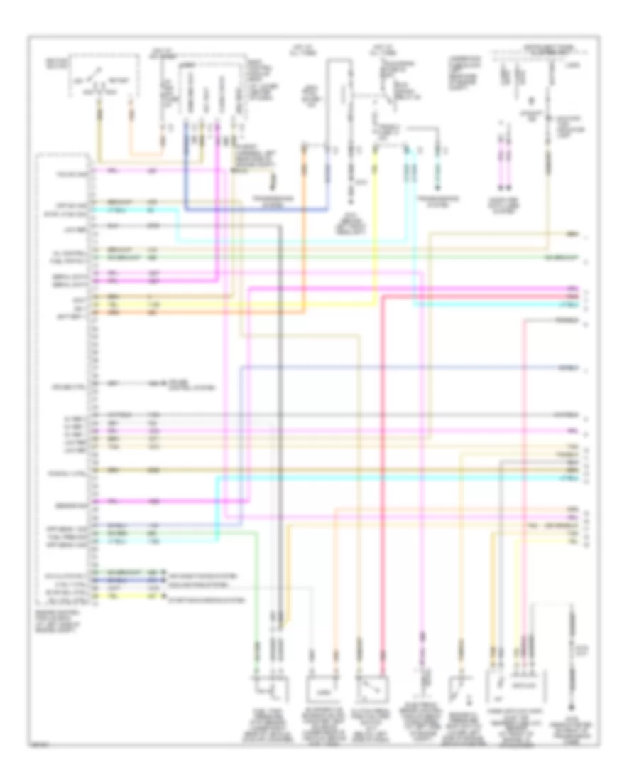
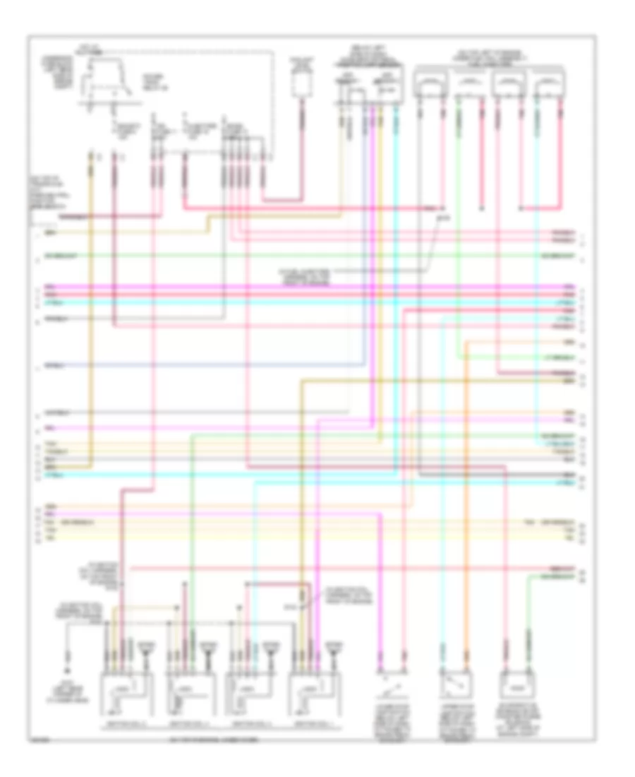
2.2L VIN F, Engine Performance Wiring Diagram (3 of 4) for Saturn Ion 3 2007
List of elements for 2.2L VIN F, Engine Performance Wiring Diagram (3 of 4) for Saturn Ion 3 2007:
- (on top left of engine, under fuel rail assembly) fuel injectors
- (on top of transaxle) (a/t) park/neutral position (pnp) switch
- A/c refrigerant pressure sensor (on lower left side of engine, below generator)
- Air pump rly fuse 44 40a (w/ cal- ifornia pzev emission system)
- Air solenoid relay 27 (w/ calif- ornia pzev emission system)
- B11
- Coolant level switch
- E11
- Ecm/etc fuse 9 15a
- Emiss fuse 10 15a
- Engine coolant temperature (ect) sensor (on right rear side of engine, near exhaust manifold)
- Engine oil pressure (eop) switch (lower rear of engine, above starter)
- Evaporative emission (evap) canister purge solenoid (at left side of engine compt)
- G105 (on lower left rear of engine, above starter)
- Hot at all times
- Ign fuse 11 10a
- Injectors fuse 16 10a
- Manifold absolute pressure (map) sensor (on top front of engine, behind throttle body)
- Pnk
- Power- train relay 29
- Red
- S139 (in fuel injectors harness, on top front of engine)
- S175 (a/t) s176 (m/t)
- Secondary air injection (air) solenoid (w/ california pzev emission system) (right side of engine)
- Underhood fuse block (left rear side of engine compt)
- Vehicle speed sensor (m/t)
- Y11
- Z11
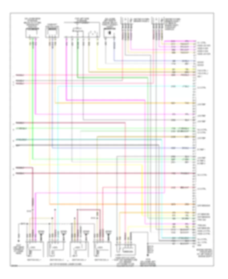
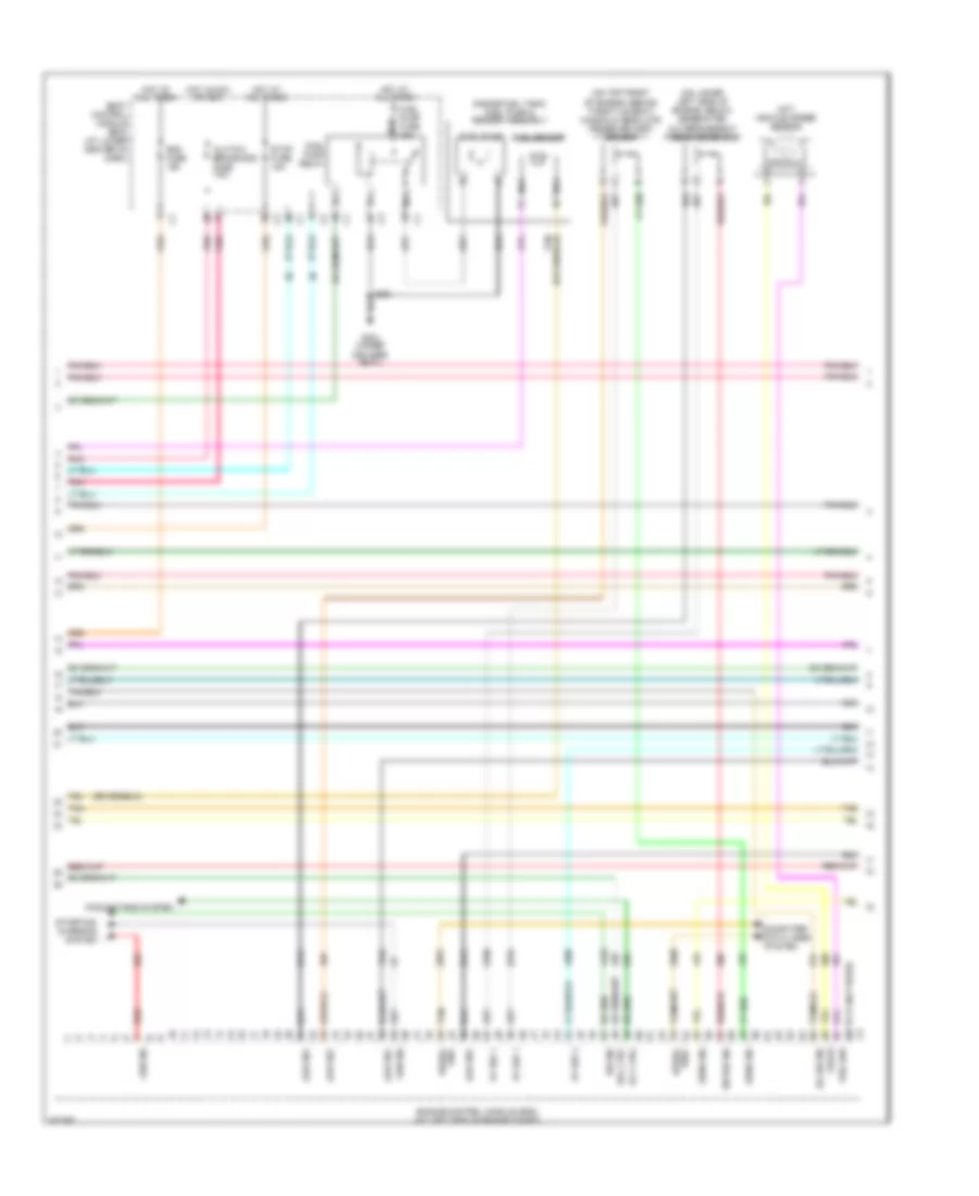
2.2L VIN F, Engine Performance Wiring Diagram (4 of 4) for Saturn Ion 3 2007
List of elements for 2.2L VIN F, Engine Performance Wiring Diagram (4 of 4) for Saturn Ion 3 2007:
- (at left side of engine compt)
- (on lower left side of engine, below throttle body) knock sensor (ks)
- (on lower rear of engine, below oil filter) crankshaft position (ckp) sensor
- (on top of engine, under cover)
- (top left side of engine) throttle body
- 5v ref 1
- 5v ref 2
- Air flow
- Camshaft position (cmp) sensor
- Ckp sens sig
- Cmp sens sig
- Engine control module (ecm)
- G105 (on lower left rear of engine, above starter)
- G107 (left rear corner of cylinder head)
- Gnd
- Heated oxygen sensor (ho2s) 1 (at rear of engine compt, in exhaust manifold)
- Heated oxygen sensor (ho2s) 2
- Ho2s hi sig
- Ho2s lo ctrl
- Ho2s low sig
- Iat
- Iat sens sig
- Ic 1 ctrl
- Ic 2 ctrl
- Ic 3 ctrl
- Ic 4 ctrl
- Ign 1
- Ignition coil 1
- Ignition coil 2
- Ignition coil 3
- Ignition coil 4
- Inj 1 ctrl
- Inj 2 ctrl
- Inj 3 ctrl
- Inj 4 ctrl
- Ks sig
- Logic
- Low ref
- Maf sens sig
- Mass air flow (maf)/ inlet air temperature (iat) sensor (attached to air cleaner outlet)
- Nca
- S140
- S141
- S142
- S175 (a/t) s176 (m/t)
- Spark plug
- Tac ctrl 1
- Tac ctrl 2
- Tan
- Tps1 sig
- Tps2 sig
2.4L VIN B
2.4L VIN B, Engine Performance Wiring Diagram (1 of 4) for Saturn Ion 3 2007
List of elements for 2.4L VIN B, Engine Performance Wiring Diagram (1 of 4) for Saturn Ion 3 2007:
- (at lower center of dash)
- (in body harness, left rear side of engine compt) s104
- 5v ref 1
- 5v ref 2
- A/c clutch rly
- A10
- Acc
- Acc volt
- Accy
- Air conditioning system
- Air flow
- App sens 1 sig
- App sens 2 sig
- Battery
- Battery +
- Body control module (bcm)
- Class 2 data
- Clutch pedal position (cpp) switch (m/t) (below left side of dash)
- Computer data lines system
- Cooling fans system
- Cpp sw sig
- Cruise control system
- Cruise ctrl
- Data class 2
- E10
- Ecm/ tcm fuse 1 10a
- Electronic brake control module (ebcm) (if equipped) (at left side of engine compt)
- Engine control module (ecm) (at left side of engine compt)
- Engine oil pressure (eop) switch (lower left side of engine, above starter)
- Evap sol ctrl
- Evaporative emission (evap) canister vent solenoid (under rear of vehicle, behind fuel tank)
- Fuel pmp rly
- Fuel pres sig
- Fuel tank pressure (ftp) sensor (under right rear of vehicle, on evap canister)
- G101 (behind left front headlight)
- G105 (near starter, on front of transmission case)
- Hi rly ctrl
- Hot at all times
- Iat
- Ign 1
- Ignition switch
- Instrument panel cluster (ipc)
- Ip/ ign sw fuse 2a
- Logic
- Low ref
- Malfunc- tion indicator lamp
- Mass air flow (maf)/ inlet air temperature (iat) sensor (at front of engine, in air cleaner)
- Mil control
- Off
- Pnk
- Pwr rly ctrl
- Rly coil ctrl
- Run
- Run/ crank relay 28
- Run/crank fuse 38 30a k1
- Run/crnk volt
- S101
- S175 (a/t)
- Sensor sig
- Serial data
- Start
- Starting/charging system
- Stop lp sw sig
- Tan
- Tan e
- Tcc sw sig
- Trans 2 fuse 13 10a
- Transmissions system
- Underhood fuse block (left rear side of engine compt)
- Up-shift ind
2.4L VIN B, Engine Performance Wiring Diagram (2 of 4) for Saturn Ion 3 2007
List of elements for 2.4L VIN B, Engine Performance Wiring Diagram (2 of 4) for Saturn Ion 3 2007:
- (below left side of dash) accelerator pedal position (app) sensor
- (in fuel injectors harness, on top front of engine)
- (in ignition coil harness, on top front of engine)
- (in ignition coil harness, on top front of engine) s140
- (in ignition coil harness, on top front of engine) s141
- (on top left of engine, under fuel rail assembly) fuel injectors
- (on top of engine, under cover)
- (on top of transaxle) (a/t) park/neutral position (pnp) switch
- App sensor 1
- App sensor 2
- Coolant level switch
- Ecm/etc fuse 9 15a
- Emiss fuse 10 15a
- Engine compt)
- Evaporative emission (evap) canister purge solenoid (at left side of
- G107 (left rear corner of cylinder head)
- Hot at all times
- Ign fuse 11 10a
- Ignition coil 1
- Ignition coil 2
- Ignition coil 3
- Ignition coil 4
- Injectors fuse 16 10a
- Logic
- Lower stop lamp switch (below left side of dash, attached to brake pedal bracket)
- Nca
- Pnk
- Pnk a
- Power- train relay 29
- S139
- S142
- Spark plug
- Tan
- Underhood fuse block (left rear side of engine compt)
- Upper stop lamp switch (below left side of dash, attached to brake pedal bracket)
2.4L VIN B, Engine Performance Wiring Diagram (3 of 4) for Saturn Ion 3 2007
List of elements for 2.4L VIN B, Engine Performance Wiring Diagram (3 of 4) for Saturn Ion 3 2007:
- (68 to 73 not used)
- (inside fuel tank) fuel pump & sender assembly
- (m/t) vehicle speed sensor
- (on lower left side of engine, below generator) a/c refrigerant pressure sensor
- (on top front of engine, behind throttle body) manifold absolute pressure (map) sensor
- 5v ref 1
- 5v ref 2
- Ba1
- Ba2
- Ba3
- Ba4
- Bcm fuse 15a
- Body control module (bcm) (at lower center of dash)
- Clutch/ brake/aos fuse 7.5a
- Computer data lines system
- Cooling fans system
- Driver's seat)
- Engine control module (ecm) (at left side of engine compt)
- Fuel pump
- Fuel pump fuse 15a
- Fuel pump relay
- Fuel sensor
- G301 (under
- Gen sig
- Hot at all times
- Hot in acc or run
- Low ref
- Nca
- Oil sw sig
- Pnk
- Red
- Refrig sig
- Rly ctrl
- S351
- Sens sig
- Serial bus+
- Serial bus-
- Sol ctrl
- Starting/ charging system
- Stop fuse 15a
- Sw sig
- Tan
- Vss hi
- Vss low
2.4L VIN B, Engine Performance Wiring Diagram (4 of 4) for Saturn Ion 3 2007
List of elements for 2.4L VIN B, Engine Performance Wiring Diagram (4 of 4) for Saturn Ion 3 2007:
- (at left side of engine compt)
- (at rear of engine compt, in exhaust manifold) heated oxygen sensor (ho2s) 1
- (in rear of engine compt, in exhaust near catalytic converter) heated oxygen sensor (ho2s) 2
- (top left side of engine) throttle body
- 5v ref
- 5v ref 1
- 5v ref 2
- Ckp sig
- Cmp sig
- Cmp sol exh
- Cmp sol in
- Crankshaft position (ckp) sensor (on lower rear of engine, below oil filter)
- Engine control module (ecm)
- Engine coolant temperature (ect) sensor (on right rear side of engine, near exhaust manifold)
- Exhaust camshaft position (cmp) actuator solenoid (top of engine, between camshaft covers)
- Exhaust camshaft position (cmp) sensor
- G105 (near starter, on front of transmission case)
- Gnd
- Ho2s hi sig
- Ho2s low ctrl
- Ho2s low sig
- Iat sens sig
- Ic 1 ctrl
- Ic 2 ctrl
- Ic 3 ctrl
- Ic 4 ctrl
- Ign 1
- Inj 1 ctrl
- Inj 2 ctrl
- Inj 3 ctrl
- Inj 4 ctrl
- Intake camshaft position (cmp) actuator solenoid (top of engine, between camshaft covers)
- Intake camshaft position (cmp) sensor
- Knock sensor (ks)
- Ks sig
- Low ref
- Maf sens sig
- Nca
- S175 (a/t)
- Tac ctrl 1
- Tac ctrl 2
- Tan
- Tan b
- Tps1
- Tps1 sig
- Tps2
- Tps2 sig

 Čeština
 Dansk
Dansk Deutsch
 Ελληνικά
 English
 Español
 Suomi
Suomi Français
 Français
 עברית
עברית Hrvatski
 Magyar
 Italiano
 日本語
日本語 한국어
한국어 Nederlands
 Polski
 Português
 Português
 Română
 Русский
 Slovenčina
 Slovenščina
 Svenska
 Türkçe
 中文 (中国)