ENGINE PERFORMANCE
3.9L VIN 1
3.9L VIN 1, Engine Performance Wiring Diagram (1 of 4) for Saturn Relay 2007
 https://portal-diagnostov.com/license.html
Automotive Electricians Portal FZCO
Automotive Electricians Portal FZCO
https://portal-diagnostov.com/license.html
https://portal-diagnostov.com/license.html
Automotive Electricians Portal FZCO
Automotive Electricians Portal FZCO
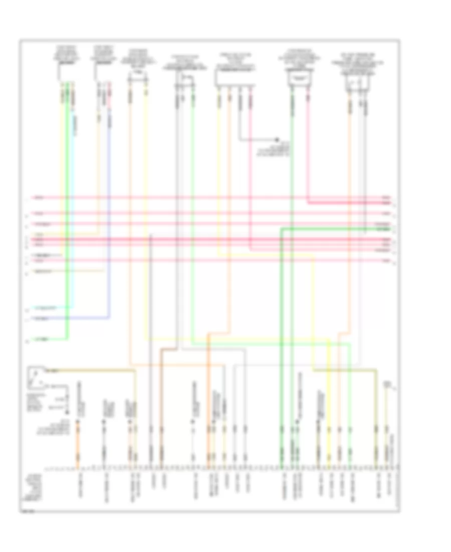
List of elements for 3.9L VIN 1, Engine Performance Wiring Diagram (1 of 4) for Saturn Relay 2007:
- (at engine to transmission stud above g115)
- (front of engine)
- (in air cleaner assembly)
- (left side of engine block)
- 5 volt ref
- Bare
- Camshaft position (cmp) actuator solenoid
- Ckp sensor sig
- Cmp sensor sig
- Engine control module (ecm)
- Engine oil pressure (eop) sensor (lower left side of engine block)
- Fuel inj 1
- Fuel inj 2
- Fuel inj 3
- Fuel inj 4
- Fuel inj 5
- Fuel inj 6
- Fuel injectors (on top of engine)
- G113
- G113 (at engine to transmission stud above g115)
- Ground
- Heated oxygen sensor (ho2s) 1 (in right bank exhaust manifold, before catalytic converter)
- Heated oxygen sensor (ho2s) 2 (in exhaust, after catalytic converter)
- Ho2s heater 1
- Ho2s heater 2
- Ho2s sig high 1
- Ho2s sig high 2
- Ho2s sig low 1
- Ho2s sig low 2
- Iat
- Iat sens sig
- Ic 3 control
- Ic1 control
- Ic2 control
- Ignition 1
- Ignition control module (icm) (top of valve cover)
- Knock sensor (ks) 1 (right side of engine block)
- Knock sensor (ks) 2
- Ks 1 sig
- Ks 2 sig
- Low ref
- Maf
- Maf sens sig
- Mass air flow (maf)/ intake air temperature (iat) sensor (in air intake, after cleaner)
- Nca
- Oil sens sig
- Pnk
- S142
- S151 (in eng harness, 15 cm from ecm c2)
- S153 (in eng harness, 10 cm from ecm c2)
- S155
- Sol high ctrl
- Tac mtr ctrl 1
- Tac mtr ctrl 2
- Tan
- Tan c
- Throttle actuator control (tac) module (rear of engine, on throttle body assembly)
- Tp sensor sig 1
- Tp sensor sig 2
3.9L VIN 1, Engine Performance Wiring Diagram (2 of 4) for Saturn Relay 2007
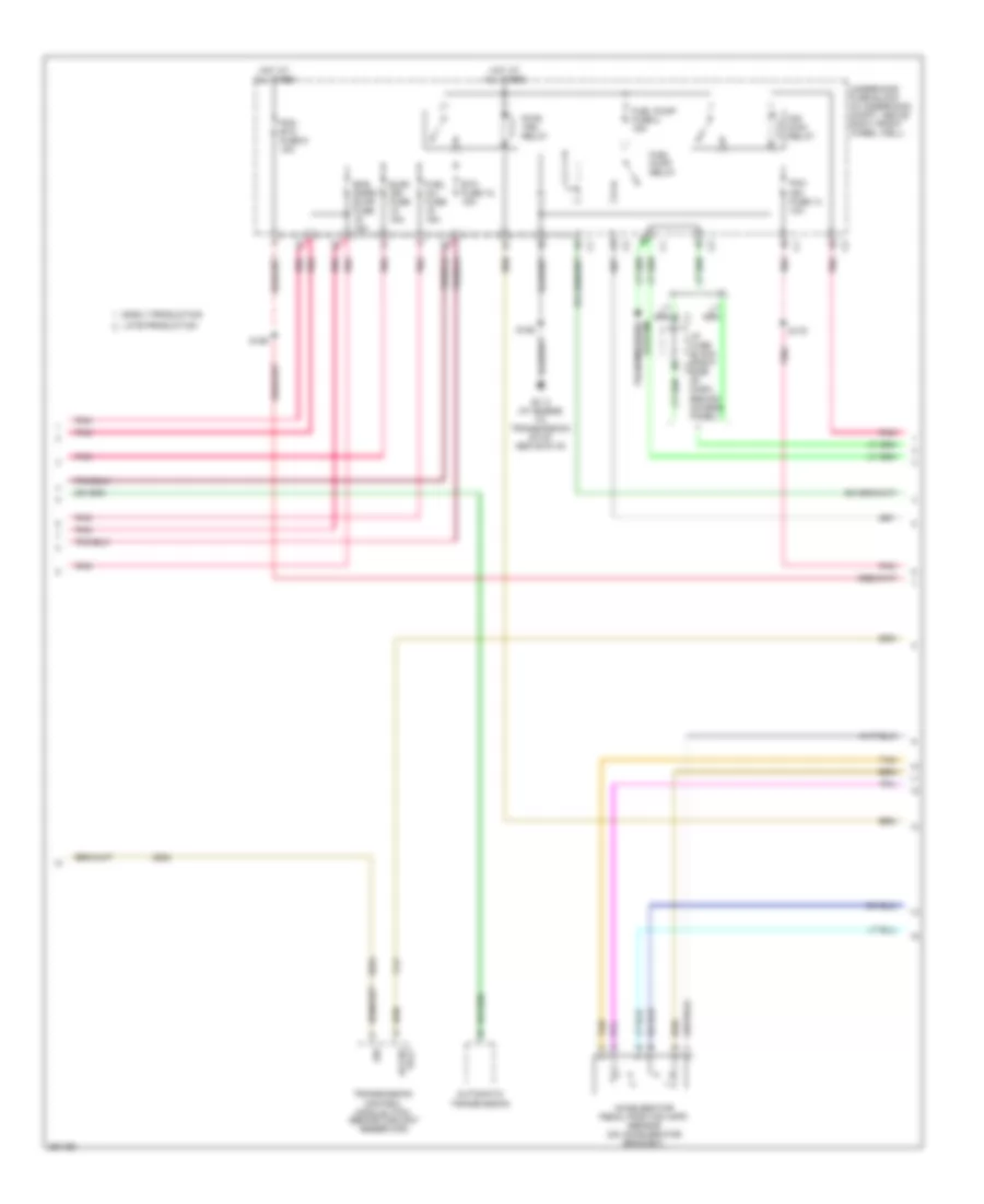
List of elements for 3.9L VIN 1, Engine Performance Wiring Diagram (2 of 4) for Saturn Relay 2007:
- (67 to 73 not used)
- (at engine to transmission stud above g115)
- (front of intake manifold) intake manifold tuning (imt) solenoid valve
- (on high pressure hose, near high pressure hose connection to a/c compressor) a/c refrigerant pressure sensor
- (top front of engine) camshaft position (cmp) sensor
- (top front of engine) crankshaft position (ckp) sensor
- (top of intake manifold) manifold absolute pressure (map) sensor
- (top rear of engine) engine coolant temperature (ect) sensor
- (top rear of intake manifold) evaporative emission (evap) canister purge solenoid valve
- 5 volt ref
- A/c sens sig
- Air conditioning system
- Anti-lock
- Brakes anti-lock
- Computer data lines system
- Deli torque sig
- Ect sens sig
- Engine control module (ecm) (in air cleaner assembly)
- Engine oil level switch (base of oil pan)
- G113
- G113 (at engine to transmission stud above g115)
- Gen cycle sig
- Gen turn sig
- Imc val ctrl
- Imt valve sig
- Lines system computer data
- Lo speed fan
- Low ref
- Map sensor sig
- Oil level sig
- Out put sig
- Park/neut sig
- Pnk
- Red
- Req torque sig
- S155
- Serial data
- Solenoid ctrl
- System
- System brakes
- System starting/charging
- Tan
3.9L VIN 1, Engine Performance Wiring Diagram (3 of 4) for Saturn Relay 2007
List of elements for 3.9L VIN 1, Engine Performance Wiring Diagram (3 of 4) for Saturn Relay 2007:
- Accelerator pedal position (app) sensor (on accelerator bracket)
- Acces volt
- Automatic transmission
- Early production
- Elec ign fuse 15a
- Eng snsr/ evap fuse 15a
- Etc fuse 18 15a
- Fuel inj fuse 15a
- Fuel pump fuse 2 15a
- Fuel pump relay
- G113 (at engine to transmission stud above g115)
- Hot at all times
- I/p fuse block (right c1 side of dash, behind access panel)
- Ign main relay
- Late production
- Pcm etc fuse 9 15a
- Pcm ign fuse 14 10a
- Pnk
- Pwr/ trn relay
- S155
- S159
- S175
- Sig
- System transmissions
- Tan
- Transmission control module (tcm) (behind coolant reservoir)
- Underhood fuse block (in underhood compt, above right front wheel well)
3.9L VIN 1, Engine Performance Wiring Diagram (4 of 4) for Saturn Relay 2007
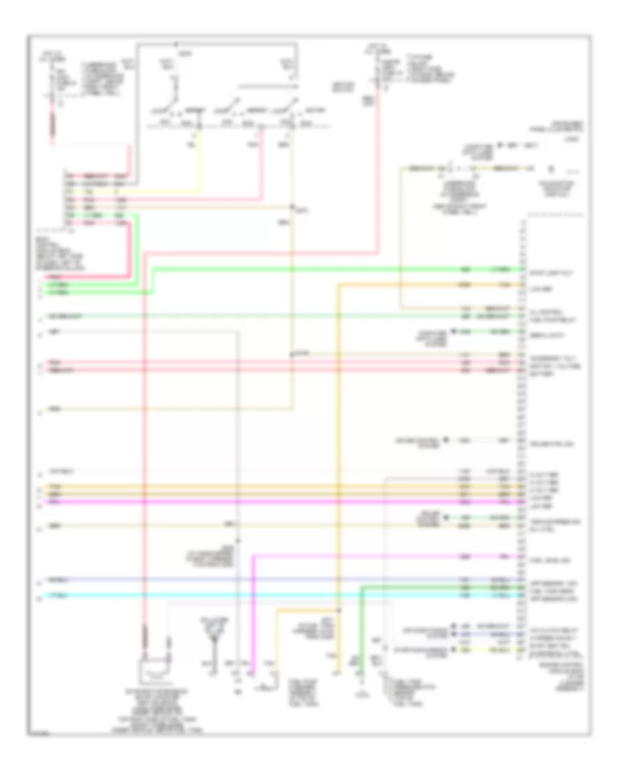
List of elements for 3.9L VIN 1, Engine Performance Wiring Diagram (4 of 4) for Saturn Relay 2007:
- (on lower left "b" pillar) g301
- 5 volt ref
- A/c clutch relay
- Acc
- Accessory volt
- Air conditioning system
- App sensor 1 sig
- App sensor 2 sig
- Battery
- Body control module (bcm) (below left side of dash, left of steering column)
- Cnstr/ vent fuse 19 10a
- Computer data lines system
- Cruise control system
- Cruise ctrl sig
- Engine control module (ecm) (in air cleaner assembly)
- Evap vent sol
- Evaporative emission (evap) canister vent solenoid (long wheelbase: under vehicle, on top right side of fuel tank) (short wheelbase: under vehicle, above fuel tank)
- Frt wsw fuse 24 15a
- Fuel level sig
- Fuel pump & sender assembly (in top of fuel tank)
- Fuel pump relay
- Fuel tank pressure (ftp) sensor (top of fuel tank)
- Fuel tank sens
- Hi speed fan rly
- Hot at all times
- I/p fuse block (right side of dash, behind access panel)
- Ignition 1 voltage
- Ignition switch
- Instrument panel cluster (ipc)
- Lock
- Logic
- Low ref
- Malfunction indicator lamp (mil)
- Mil control
- Pnk
- Rly ctrl
- Run
- S139
- S273
- S279
- S306 (w/ handicapped) (in body harness, 8 cm from c200)
- S371 (in fuel tank harness, 30 cm from c305)
- Serial data
- Start
- Starter rly ctrl
- Starting/charging system
- Stop lamp volt
- Tan
- Underhood fuse block (in underhood compt, (above right front wheel well)
- Underhood fuse block (in underhood compt, above right front wheel well)
- Vehicle speed sig

 Čeština
 Dansk
Dansk Deutsch
 Ελληνικά
 English
 Español
 Suomi
Suomi Français
 Français
 עברית
עברית Hrvatski
 Magyar
 Italiano
 日本語
日本語 한국어
한국어 Nederlands
 Polski
 Português
 Português
 Română
 Русский
 Slovenčina
 Slovenščina
 Svenska
 Türkçe
 中文 (中国)