ENGINE PERFORMANCE
1.8L
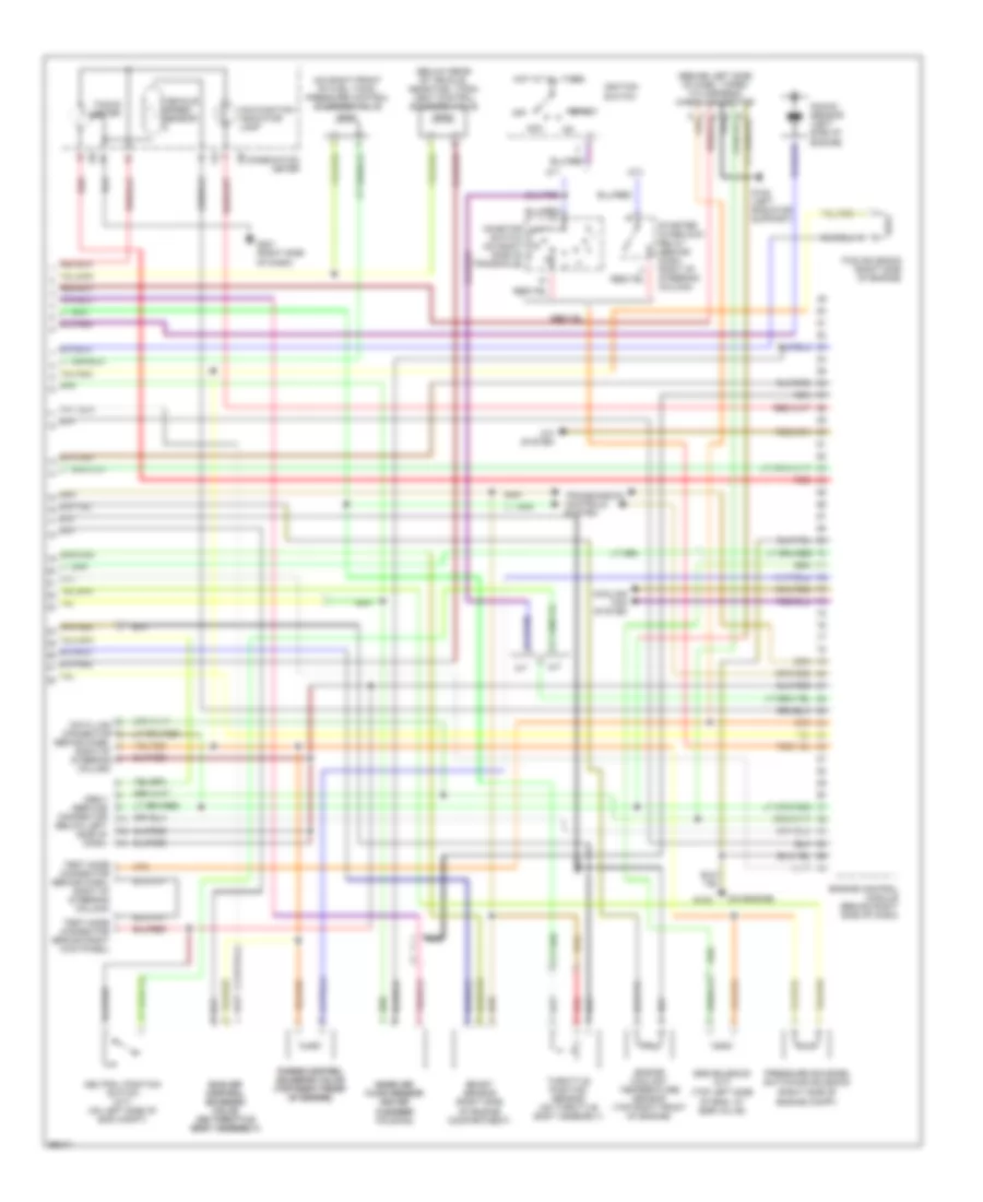
1.8L, Engine Performance Wiring Diagrams (1 of 2) for Subaru Impreza Brighton 1997
 https://portal-diagnostov.com/license.html
Automotive Electricians Portal FZCO
Automotive Electricians Portal FZCO
https://portal-diagnostov.com/license.html
https://portal-diagnostov.com/license.html
Automotive Electricians Portal FZCO
Automotive Electricians Portal FZCO
List of elements for 1.8L, Engine Performance Wiring Diagrams (1 of 2) for Subaru Impreza Brighton 1997:
- (left shock tower) g102
- (on engine)
- (right side of dash) g201
- A/c system
- B52
- Camshaft position sensor (left front of eng)
- Crankshaft position sensor (lower front of eng)
- Engine control module (behind right side of dash)
- F37
- F40
- Fuel gauge module (below rear of vehicle, in fuel tank)
- Fuel injectors
- Fuel level sensor
- Fuel pump relay (behind left side of dash)
- Fuel tank pressure sensor (right side of trunk)
- Fuel temperature sensor
- Fuse & relay box
- Fuse 10a
- Fuse 15a
- G133
- G133 (on engine)
- Hot at all times
- Hot in run
- Ignition coil (top front of eng)
- Ignitor (center of firewall)
- Main fuse box
- Main relay (behind left side of dash)
- Nca
- Or start
- Oxygen sensor (front) (on front of front catalytic converter)
- Oxygen sensor (rear) (on rear of rear catalytic converter)
- Red
- Sbf-2 30a
- Shield j/c (brhind left of dash)
- Shield joint connector (right kick panel)
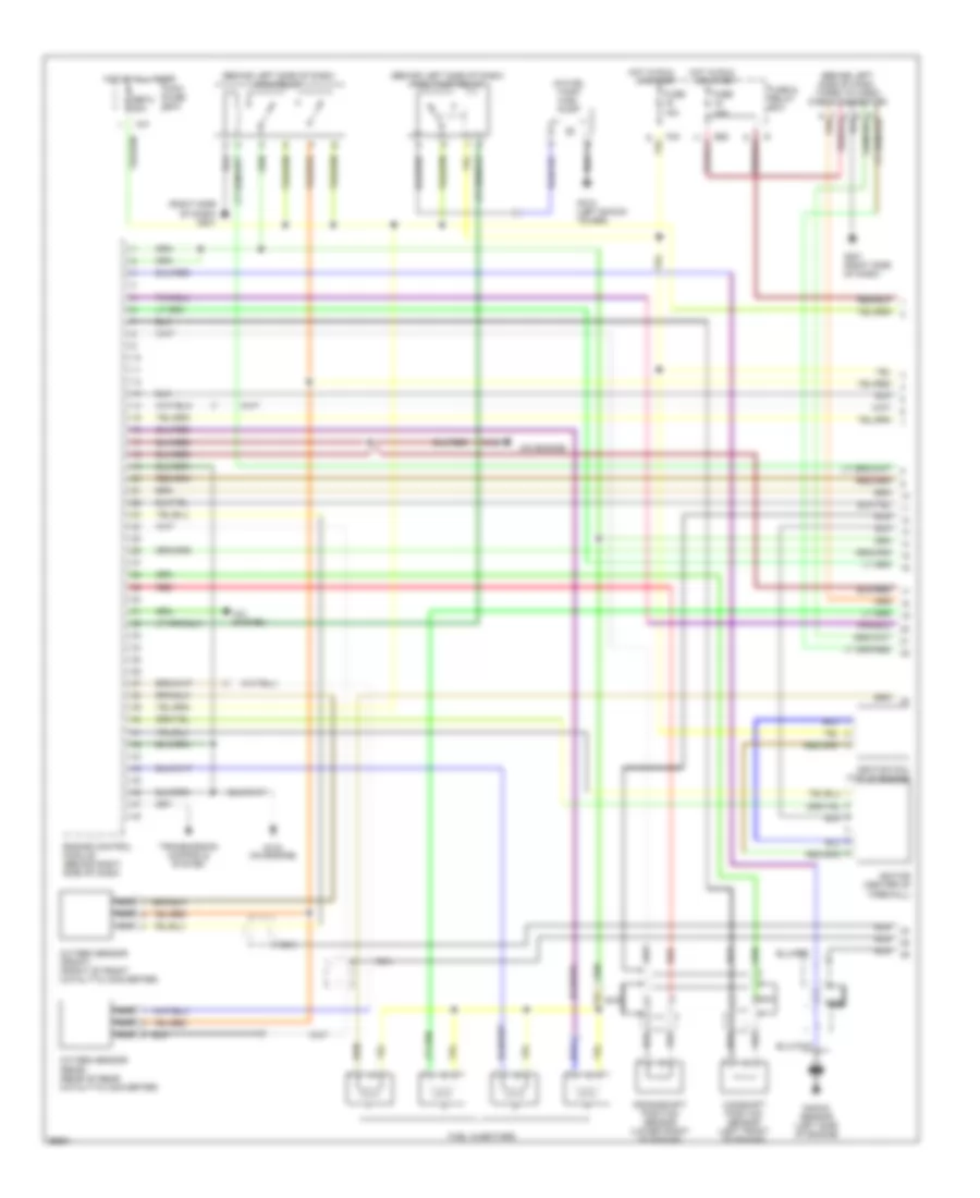
1.8L, Engine Performance Wiring Diagrams (2 of 2) for Subaru Impreza Brighton 1997
List of elements for 1.8L, Engine Performance Wiring Diagrams (2 of 2) for Subaru Impreza Brighton 1997:
- (behind dash, right of steering column)
- (behind left side of dash, taped to harness) check connector
- (below rear of vehicle, near fuel tank) vent control solenoid valve
- (on air (on air cleaner cleaner housing)
- (on engine)
- (on right front of fuel tank) pressure control solenoid valve
- (right side of engine compartment)
- (right side of engine compt)
- (top left side of eng, at egr valve)
- A/c system
- A/t
- Acc
- Boost sensor
- Combination meter
- Cooling fan system
- Data link connector
- Egr solenoid (a/t)
- Engine control module (behind right side of dash)
- Engine coolant temperature sensor (top right front of engine)
- Ficd solenoid (right side of engine)
- G108 (left radiator support)
- G133
- G201 (right side of dash)
- Hot at all times
- I10
- I12
- Idle air idle air control control solenoid solenoid valve valve (on throttle (on throttle body assembly) body assembly)
- Ignition switch
- Inhibitor switch (on right side of transaxle)
- Knock sensor (left side of engine)
- M/t
- Malfunction indicator lamp
- Mass air mass air flow sensor flow sensor
- Nca
- Neutral position switch (m/t) (on left side of eng compt)
- Obd-ii service connector (below left side of dash)
- Off
- Pressure sources switching solenoid
- Purge control purge control solenoid valve solenoid valve (top right front (top right front of engine) of engine)
- Red
- Start
- Starter interlock relay (behind dash, right of steering column)
- Tacho- meter
- Test mode connector (behind dash, right of steering column)
- Test mode connector (brhind right kick panel)
- Throttle position sensor (on throttle body assembly)
- Transmission controls system
- Vehicle speed sensor
2.2L
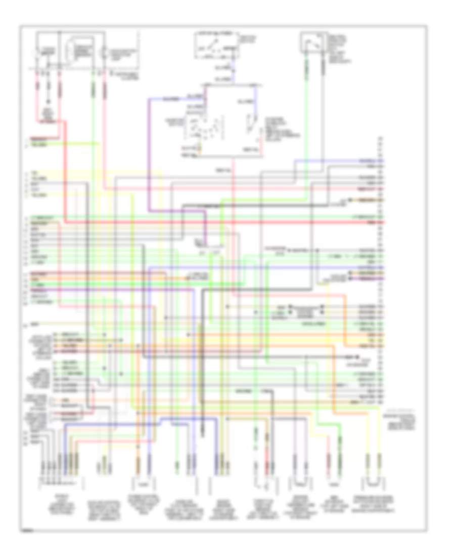
2.2L, Engine Performance Wiring Diagrams (1 of 2) for Subaru Impreza Brighton 1997
List of elements for 2.2L, Engine Performance Wiring Diagrams (1 of 2) for Subaru Impreza Brighton 1997:
- (behind left side of dash) fuel pump relay
- (behind left side of dash) main relay
- (behind left side of dash, taped to harn) check connector
- (in fuel tank) fuel pump
- (on engine)
- (right side of dash) g201
- A/c system
- B52
- Camshaft position sensor (left front of engine)
- Crankshaft position sensor (lower front of engine)
- Engine control module (behind right side of dash)
- F37
- F40
- Fuel injectors
- Fuse & relay box
- Fuse 10a
- Fuse 15a
- G102 (left shock tower)
- G133
- G133 (on engine)
- G201 (right side of dash)
- Hot at all times
- Hot in run
- Ignition coil (top of engine)
- Ignitor (center of firewall)
- Knock sensor (left side of engine)
- Main fuse box
- Nca
- Or start
- Oxygen sensor (front) (front of front catalytic converter)
- Oxygen sensor (rear) (rear of rear catalytic converter)
- Red
- Sbf-2 30a
- Transmission controls system
2.2L, Engine Performance Wiring Diagrams (2 of 2) for Subaru Impreza Brighton 1997
List of elements for 2.2L, Engine Performance Wiring Diagrams (2 of 2) for Subaru Impreza Brighton 1997:
- (on engine)
- (part of air intake assembly, neat to air cleaner box)
- (right side of engine compartment)
- (top left side of engine)
- A/c system
- A/t
- Acc
- Boost sensor
- Cooling fan system
- Data link connector (on dash,
- Egr solenoid
- Engine control module (behind right (side of dash)
- Engine coolant temperature sensor (top right front of engine)
- G133
- G201 (right side of dash)
- Hot at all times
- I10
- I12
- Idle air control solenoid valve (on top of eng, near throttle body assembly)
- Ignition switch
- Inhibitor switch
- Instrument cluster
- Left of steering column)
- M/t
- Malfunction indicator lamp
- Mass air flow sensor
- Nca
- Neutral position switch (m/t) (on left side of eng compt)
- Obd-ii service connector (left side of dash)
- Off
- Pressure sources switching solenoid
- Purge control solenoid valve (on top right front of eng)
- Red
- Shield joint connector (behind right kick panel)
- Start
- Starter interlock relay (behind dash, left of steering column)
- Tacho- meter
- Test mode connector (left side of dash)
- Test mode connector (right of dash)
- Throttle position sensor (on throttle body assembly)
- Transmission control system
- Vehicle speed sensor

 Čeština
 Dansk
Dansk Deutsch
 Ελληνικά
 English
 Español
 Suomi
Suomi Français
 Français
 עברית
עברית Hrvatski
 Magyar
 Italiano
 日本語
日本語 한국어
한국어 Nederlands
 Polski
 Português
 Português
 Română
 Русский
 Slovenčina
 Slovenščina
 Svenska
 Türkçe
 中文 (中国)