ENGINE PERFORMANCE
1.3L
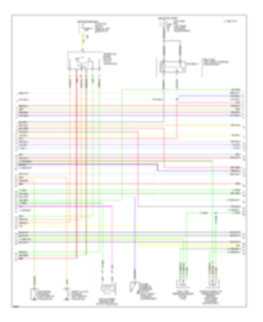
1.3L, Engine Performance Wiring Diagrams (1 of 3) for Suzuki Swift 1996
 https://portal-diagnostov.com/license.html
Automotive Electricians Portal FZCO
Automotive Electricians Portal FZCO
https://portal-diagnostov.com/license.html
https://portal-diagnostov.com/license.html
Automotive Electricians Portal FZCO
Automotive Electricians Portal FZCO
List of elements for 1.3L, Engine Performance Wiring Diagrams (1 of 3) for Suzuki Swift 1996:
- (center rear of engine) g115
- 2 pos sig
- 2nd brk sol
- A/c amplifier
- A/c cut-out
- A/c idle-up sig
- Air conditioning
- C 1995 vftc
- C21
- C22
- C23
- Camshaft position (cmp) sensor
- Cooling fan system
- Crankshaft position (ckp) sensor (bottom of engine, by crankshaft pulley)
- D pos sig
- Data link coupler (left side of i/p)
- Defogger
- Diag input
- Diode (behind center of i/p)
- Dir clutch sol
- Distributor (left side of engine)
- Distributor cap
- Duty check data link connector (left rear side of engine compt)
- E23
- E63
- Early fuel evaporative (efe) heater (near intake manifold)
- Ecm ground
- Ect input
- Efe on sig
- Egr bypass cntrl
- Egr sol cntrl
- Elec idle-up sig
- Engine start sig
- Evap can cntrl
- Evap can vent
- Fuel level
- Fuel press in
- Fuel pump relay
- Fuse 15 15a
- G115 (center rear of engine, on intake manifold)
- Ground
- Ho2s1 heater
- Ho2s1 input
- Ho2s2 heater
- Ho2s2 input
- Hot at all times
- Iat input
- Idle switch sig
- Ign coil control
- Ign pwr input
- Ign ref
- Ign trig input
- Ign trigger sig
- Igniter (left side of engine compt)
- Ignition
- Ignition coil (left side of engine compt)
- Inj control
- Instrument cluster system
- Instrument cluster system (tachometer)
- Interior lights
- Isc motor cntrl
- Isca relay cntrl
- Junction block (behind left side of i/p)
- L pos sig
- Main fuse box (left rear of engine compartment)
- Map input
- Memory
- Mil ind control
- N pos sig
- Nca
- Noise suppressor filter (left rear of engine compt)
- Not used
- P pos sig
- Pcm ground
- Pnk
- Powertrain control module (pcm) (a/t) engine control module (ecm) (m/t) (behind right side of i/p)
- Ptc fuse 30a
- Ptc relay (early fuel evaporation)
- Ptc relay cntrl
- Pwr steer press
- R pos sig
- Rad fan relay
- Red
- Ref voltage
- Relay box (left front of engine compartment)
- Relay control
- Sensor ground
- Serial data in
- Starting system
- System
- Tank press cntrl
- Test sw input
- To spark plugs
- Tp input
- Upshift ind cntrl
- Vss input (a/t)
- Vss input (m/t)
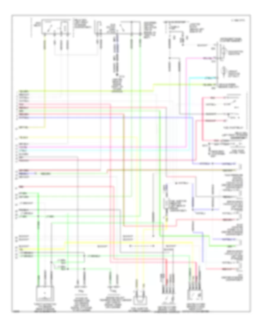
1.3L, Engine Performance Wiring Diagrams (2 of 3) for Suzuki Swift 1996
List of elements for 1.3L, Engine Performance Wiring Diagrams (2 of 3) for Suzuki Swift 1996:
- (left rear of engine compartment)
- 2nd brake solenoid (left rear of transaxle)
- C 1995 vftc
- Direct clutch solenoid (left rear of transaxle)
- E63
- Fi fuse 15a e23
- Fuel tank pressure sensor (in fuel tank)
- Fuse 16 15a
- Hot at all times
- Hot in on or start
- Junction block (behind left side of i/p)
- Main fuse box
- Main relay
- Manifold absolute pressure (map) sensor (right rear of engine compartment)
- N d
- Pnk
- Power steering pressure switch (right front of engine compartment)
- Red
- Relay box (left front of engine compartment)
- Transaxle range switch (top of transaxle)
- Vehicle speed sensor (vss) (top of transaxle)
1.3L, Engine Performance Wiring Diagrams (3 of 3) for Suzuki Swift 1996
List of elements for 1.3L, Engine Performance Wiring Diagrams (3 of 3) for Suzuki Swift 1996:
- (a/t)
- (center rear of engine compt, on intake manifold)
- (left side of engine, under air cleaner)
- (m/t)
- (near deck lid striker) g407
- 1995 vftc c
- Ccv (center of engine compartment)
- Compartment)
- E62
- Egr solenoid vacauum valve 2 (left side of engine)
- Egr solenoid vacuum valve 1 (left side of engine)
- Engine coolant temperature (ect) sensor
- Evap canister purge valve (center of engine compartment)
- Fuel injector (in throttle body)
- Fuel injector resistor (left rear of engine compartment)
- Fuel pump (in fuel tank)
- Fuel pump relay
- Fuse 21 15a
- G01
- G08
- G115
- G15
- Heated oxygen sensor 1 (ho2s) (in exhaust manifold)
- Heated oxygen sensor 2 (ho2s) (near 3-way catalytic converter)
- Hot in on or start
- Idle speed control (isc) motor (top of engine, on throttle body)
- Idle switch open at idle
- Instrument panel cluster assembly
- Intake air temperature (iat) sensor (left side of engine, attached to air cleaner)
- Isca
- Junction block (behind left side of i/p)
- Malfunction indicator
- Nca
- Pnk
- Red
- Relay
- Relay box (left front of engine
- Relay box (left front of engine compartment)
- S313
- Tank pressure control solenoid vacuum valve (center of engine compartment)
- Throttle position (tp) sensor (rear of engine above generator)
- Upshift indicator (m/t only)
- Vehicle speed sensor (vss) (m/t)

 Čeština
 Dansk
Dansk Deutsch
 Ελληνικά
 English
 Español
 Suomi
Suomi Français
 Français
 עברית
עברית Hrvatski
 Magyar
 Italiano
 日本語
日本語 한국어
한국어 Nederlands
 Polski
 Português
 Português
 Română
 Русский
 Slovenčina
 Slovenščina
 Svenska
 Türkçe
 中文 (中国)