ENGINE PERFORMANCE
3.5L
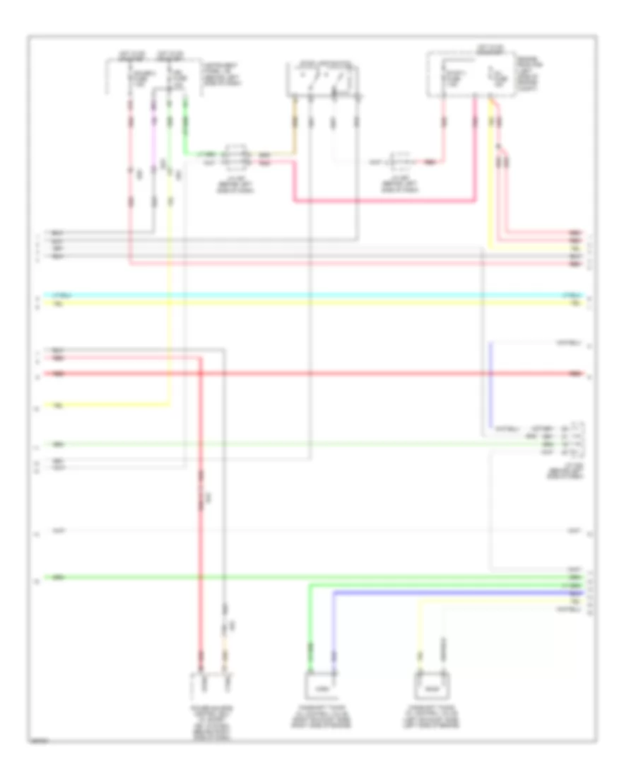
3.5L, Engine Performance Wiring Diagram (1 of 5) for Toyota Avalon 2012
 https://portal-diagnostov.com/license.html
Automotive Electricians Portal FZCO
Automotive Electricians Portal FZCO
https://portal-diagnostov.com/license.html
https://portal-diagnostov.com/license.html
Automotive Electricians Portal FZCO
Automotive Electricians Portal FZCO
List of elements for 3.5L, Engine Performance Wiring Diagram (1 of 5) for Toyota Avalon 2012:
- (behind left side of dash) j/c a57
- (left front of engine compt) j/c a51
- +b2
- +bm
- A/f fuse 25a
- A/f relay
- A55
- Accelerator position sensor (behind left center of dash)
- Accr
- Ad2
- Ad9
- Aicv
- Batt
- C/ opn relay
- Canh
- Canl
- Ccs
- Computer data lines system
- Cruise control system
- D63
- E44
- Efi 1 fuse 25a
- Efi 2 fuse 10a
- Efi relay
- Efii
- Efio
- Engine control module (right rear of engine compt)
- Engine room j/b (left side of engine compt)
- Engine room r/b (left side of engine compt)
- Epa
- Epa2
- Etcs fuse 10a
- Fuel suction pump & gauge assembly (fuel tank)
- H10
- Hot at all times
- Id code box (behind left side of dash)
- Igsw
- Imi
- Imo
- J/c a42 (behind left side of dash)
- J/c a57 (behind left side of dash)
- J/c d63 & e44 (behind right side of dash)
- K1 (left "c" pillar)
- Ka2
- Mpmp
- Mrel
- Pnk
- Pump
- Red
- Sftd
- Sftu
- Spd
- St1-
- Sta
- Starting/charging system
- Stop 1 fuse 15a
- Stp
- Stsw
- Tach
- Transmissions system
- Transponder key ecu (behind left side of dash)
- Vcp2
- Vcpa
- Vpa
- Vpa2
- Vpmp
- Vsv (air intake control) (left side of engine compt)
- W/ smart key system
- W/o smart key system
3.5L, Engine Performance Wiring Diagram (2 of 5) for Toyota Avalon 2012
List of elements for 3.5L, Engine Performance Wiring Diagram (2 of 5) for Toyota Avalon 2012:
- Ad2
- Ba2
- Camshaft timing oil control valve (left exhaust side) (left side of engine)
- Camshaft timing oil control valve (right exhaust side) (right side of engine)
- Ctsw
- Da2
- Ed5
- Engine room r/b (left side of engine compt)
- G12
- Gauge 2 fuse 7.5a
- Hot in on or start
- Ign fuse 10a
- Inj fuse 15a
- Instrument panel j/b (behind left side of dash)
- J/c a42 (behind left side of dash)
- J/c a57 (behind left side of dash)
- J/c a67 (behind left side of dash)
- M13
- Pnk
- Power source control ecu (w/ smart key system) (behind right side of dash)
- Red
- Stop 3 fuse 7.5a
- Stop lamp switch
- Stsw
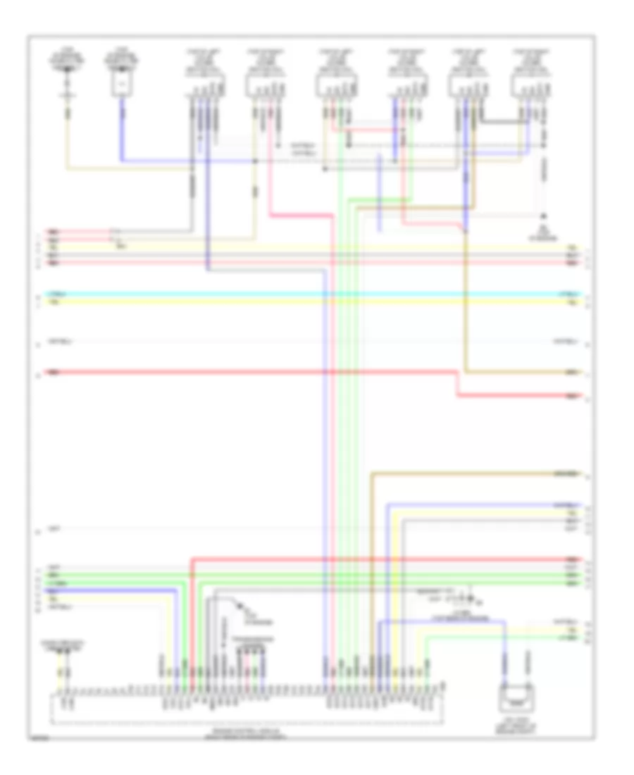
3.5L, Engine Performance Wiring Diagram (3 of 5) for Toyota Avalon 2012
List of elements for 3.5L, Engine Performance Wiring Diagram (3 of 5) for Toyota Avalon 2012:
- (top of engine) noise filter (ignition 1)
- (top of engine) noise filter (ignition 2)
- (top of left valve cover) ignition coil
- (top of right valve cover) ignition coil
- Acm
- B1 (top of engine)
- B2 (top of engine)
- B50
- Ba1
- Can+
- Can-
- Computer data lines system
- E01
- E02
- E04
- E05
- Engine control module (right rear of engine compt)
- Ge01
- Gnd
- Ht1b
- Ht2b
- Igf
- Igt1
- Igt2
- Igt3
- Igt4
- Igt5
- Igt6
- J/c b52 (top rear of engine)
- Me01
- Oe1+
- Oe1-
- Oe2+
- Oe2-
- Pnk
- Red
- Transmissions system
- Vsv (acm) (left front of engine compt)
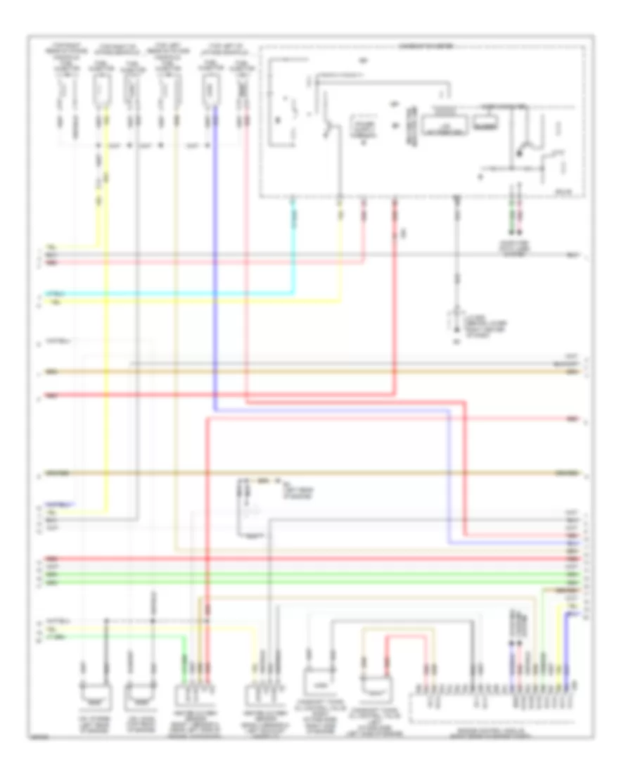
3.5L, Engine Performance Wiring Diagram (4 of 5) for Toyota Avalon 2012
List of elements for 3.5L, Engine Performance Wiring Diagram (4 of 5) for Toyota Avalon 2012:
- (top left of intake manifold)
- (top left rear of intake manifold) fuel injector
- (top right of intake manifold)
- (top right rear of intake manifold) fuel injector
- B3 (left rear of engine)
- B50
- Ba1
- Buzzer
- Camshaft timing oil control valve (left intake side) (left side of engine)
- Camshaft timing oil control valve (right intake side) (right side of engine)
- Combination meter
- Computer data lines system
- Ecu-b
- Ed5
- Engine control module (right rear of engine compt)
- Ev1+
- Ev2+
- Ex1b
- Ex2b
- Fuel injector
- Heated oxygen sensor (bank 1 sensor 2) (near left side of engine, in exhaust)
- Heated oxygen sensor (bank 2 sensor 2) (left exhaust manifold)
- Ht1b
- Ht2b
- Ig+
- Indicator lamp malfunction
- J/c e29 (behind lower right center of dash)
- Lcd (a/t position)
- Micro computer
- Nca
- Nsw
- Oc1+
- Oc1-
- Oc2+
- Oc2-
- Ox1b
- Ox2b
- Pnk
- Red
- Star
- System charging starting/
- Vsv (acis) (top front of engine)
- Vsv (purge) (left rear of engine)
- Vv1+
- Vv2+
3.5L, Engine Performance Wiring Diagram (5 of 5) for Toyota Avalon 2012
List of elements for 3.5L, Engine Performance Wiring Diagram (5 of 5) for Toyota Avalon 2012:
- (left front of engine) crankshaft position sensor
- (left side of engine, in exhaust pipe) air fuel ratio sensor (bank 2 sensor 1)
- (right side of engine, in exhaust pipe) air fuel ratio sensor (bank 1 sensor 1)
- (top of engine)
- (top of engine) knock control sensor (bank 1)
- (top of engine) knock control sensor (bank 2)
- (top rear of engine) throttle body assembly
- A1a+
- A1a-
- A2a+
- A2a-
- Acis
- B1 (top of engine)
- B3 (left rear of engine)
- B50
- Ba1
- Ba2
- Br1
- Canister pressure sensor
- Canister pump module (under center of vehicle)
- E03
- E2g
- Ekn2
- Eknk
- Engine control module (right rear of engine compt)
- Engine coolant temperature sensor (top rear of engine)
- Eppm
- Eta
- Etha
- Ethw
- Ev1-
- Ev2-
- Ex+
- Ex-
- Ha1a
- Ha2a
- Igf1
- J/c b52 (top rear of engine)
- Ka2
- Knk1
- Knk2
- Leak detection pump
- Mass air flow meter (left side of engine compt, part of air intake assembly)
- Nca
- Ne+
- Ne-
- Ox1b
- Ox2b
- Pnk
- Power steering oil pressure switch (right side of engine)
- Ppmp
- Prg
- Psw
- Red
- Tha
- Thw
- Vc2
- Vce1
- Vce2
- Vcpp
- Vcta
- Vcv1
- Vcv2
- Vent valve
- Vta1
- Vta2
- Vv1-
- Vv2-
- Vvl+
- Vvl-
- Vvr+
- Vvr-
- Vvt sensor (bank 1 exhaust side) (right side of engine)
- Vvt sensor (bank 1 intake side) (right front of engine)
- Vvt sensor (bank 2 exhaust side) (left front of engine)
- Vvt sensor (bank 2 intake side) (left front of engine)

 Čeština
 Dansk
Dansk Deutsch
 Ελληνικά
 English
 Español
 Suomi
Suomi Français
 Français
 עברית
עברית Hrvatski
 Magyar
 Italiano
 日本語
日本語 한국어
한국어 Nederlands
 Polski
 Português
 Português
 Română
 Русский
 Slovenčina
 Slovenščina
 Svenska
 Türkçe
 中文 (中国)