ENGINE PERFORMANCE
3.0L
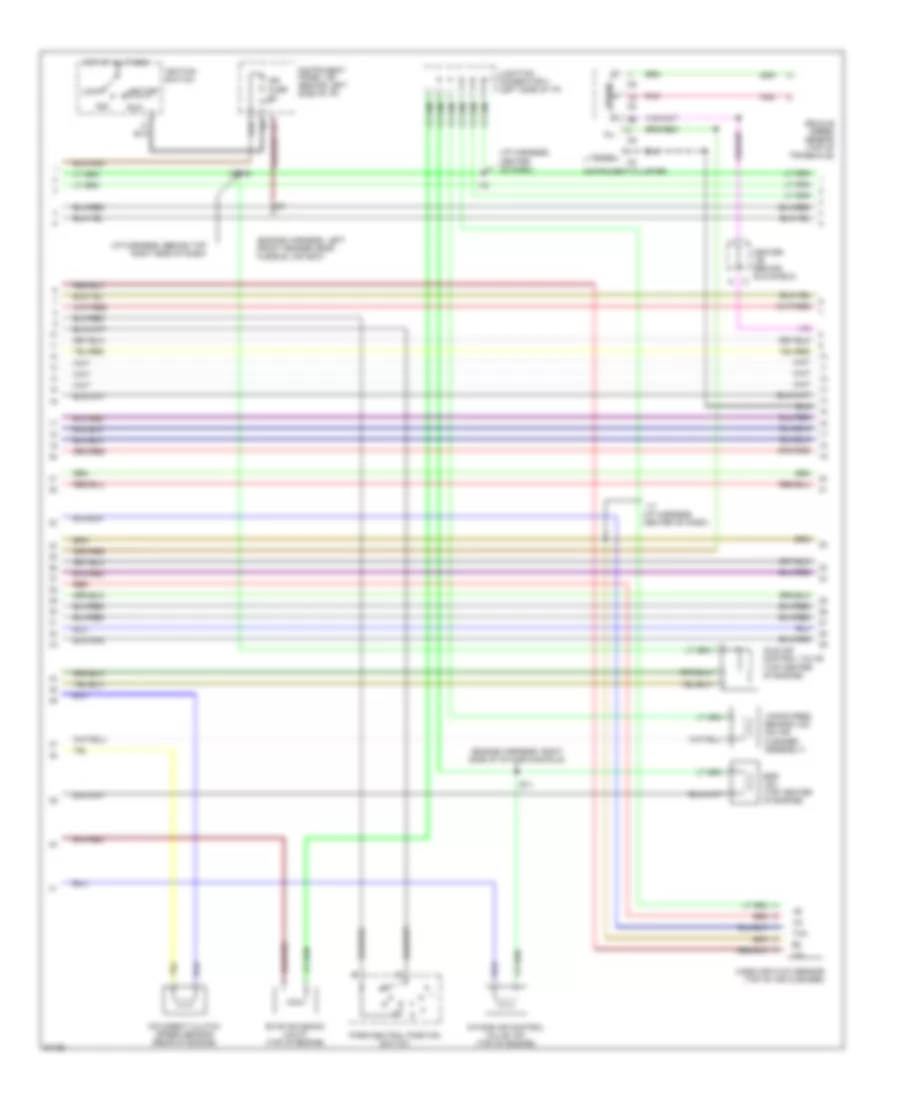
3.0L, Engine Performance Wiring Diagrams (1 of 3) for Toyota Avalon XL 1997
 https://portal-diagnostov.com/license.html
Automotive Electricians Portal FZCO
Automotive Electricians Portal FZCO
https://portal-diagnostov.com/license.html
https://portal-diagnostov.com/license.html
Automotive Electricians Portal FZCO
Automotive Electricians Portal FZCO
List of elements for 3.0L, Engine Performance Wiring Diagrams (1 of 3) for Toyota Avalon XL 1997:
- #10
- #20
- #30
- #40
- #50
- #60
- (engine harness, center of intake manifold)
- (engine harness, left side of intake manifold )
- (engine harness, left side of intake manifold)
- (i/p harness, behind center of dash)
- (left side of engine compartment)
- Acis
- Conn e6
- Conn e7
- Conn e8
- Cooling fans system
- E01
- E02
- E03
- E10
- Efi fuse 15a
- Efi main relay
- Egls
- Egr
- Engine control module (behind right side of i/p)
- Engine room j/b
- Evp1
- F12
- G100 (front left fender)
- G131 (left intake manifold)
- G22+
- Hot at all times
- Hot in start
- Htl
- Htr
- I17
- Igf
- Igt2
- Igt3
- Igt4
- Injector #1
- Injector #2
- Injector #3
- Injector #4
- Injector #5
- Injector #6
- Instrument panel j/b (behind left side of i/p)
- Knkl
- Knkr
- Nc2+
- Nc2-
- Ne+
- Ne-
- Nsw
- Oxl
- Oxr
- Pnk
- Power steering oil pressure switch (right rear of engine compt)
- Ptnk
- Red
- Rsc
- Rso
- Sln-
- Sta
- Starter fuse 5a
- Te1
- Tha
- Thg
- Thw
- Tpc
- Transmissions system
- Vapor pressure sensor (center of safety wall)
- Vg-
- Vta
3.0L, Engine Performance Wiring Diagrams (2 of 3) for Toyota Avalon XL 1997
List of elements for 3.0L, Engine Performance Wiring Diagrams (2 of 3) for Toyota Avalon XL 1997:
- (engine harness, left front fender near fusible link box)
- (engine harness, right side of intake manifold)
- (i/p harness, behind top right side of dash)
- (i/p harness, center of dash)
- Acc
- Center j/b (behind glove box)
- D10
- E11
- Egr vsv (top center of engine)
- Evap solenoid (calif) (top of engine)
- Hot at all times
- I16
- I17 (i/p harness, center of dash)
- I19/i20
- Idle air control valve (top center of engine)
- Ign fuse 5a
- Ignition switch
- Instrument cluster
- Instrument panel j/b (behind left side of i/p)
- Intake air control valve vsv (top of engine)
- Junction connector 3 (left side of i/p)
- Lock
- Mass air flow sensor (top of air cleaner)
- Mil
- O/d direct clutch speed sensor (rear of engine)
- Park/neutral position switch
- Pnk
- Red
- Run
- Speed
- Start
- Tacho
- Tha
- Vapor pres sensor vsv (on air cleaner assembly)
- Vehicle speed sensor (top of transaxle)
- Vg-
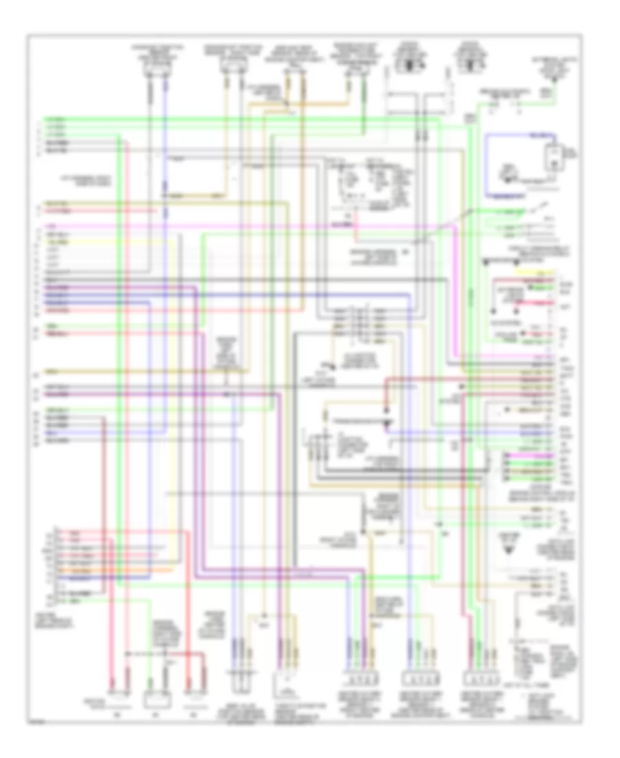
3.0L, Engine Performance Wiring Diagrams (3 of 3) for Toyota Avalon XL 1997
List of elements for 3.0L, Engine Performance Wiring Diagrams (3 of 3) for Toyota Avalon XL 1997:
- (behind glove box) center j/b
- (behind right side of i/p)
- (center of i/p)
- (eng harn, center of intake manifold)
- (engine harn, center of intake manifold)
- (engine harn, left side of intake manifold)
- (engine harness, left side of intake manifold)
- (engine harness, right side of intake manifold)
- (engine, harness, right of air cleaner assembly)
- (i/p harness, center of dash)
- (i/p harness, right side of dash)
- (i/p harness, top right side of dash)
- (left intake manifold)
- (rear of
- (right side
- (top right
- +b +b
- A/c
- A/c system
- Act
- Anti-lock
- Bat
- Batt
- Brakes system (w/ traction control)
- Camshaft position sensor (center front of engine)
- Circuit opening relay (behind glove box)
- Conn e5
- Cooling fans
- Crankshaft position
- Data link connector #1 (center rear of engine)
- Data link connector #3 (left side of i/p)
- Def i/up fuse 5a
- Defogger on
- E10
- E11
- Efi+
- Efi-
- Egr gas temp
- Egr valve position sensor (top center rear of engine)
- Els
- Els2
- Engine compartment)
- Engine control module
- Engine coolant temperature
- Engine room j/b (left side of engine compart- ment)
- Exterior lights system
- Exterior lights system (stop light switch)
- Fuel pump
- G131
- G131 (right intake manifold)
- G206
- G904 (left c pillar)
- Gnd
- Heated oxygen sensor (bank 1, sensor 1) (center rear of engine compartment)
- Heated oxygen sensor (bank 1, sensor 2) (rear of center console)
- Heated oxygen sensor (bank 2, sensor 1) (front center of engine)
- Hot at all times
- Hot w/
- Ht ht
- Hts
- I17
- I19/ i20
- Idle-up diodes
- Igf
- Igniter (left rear of engine compt)
- Ignition coils
- Instru- ment panel j/b (left side of i/p)
- J2 junction connector (center of i/p)
- J4 junction connector (left side of i/p)
- Knock sensor 1 (top center of engine)
- Knock sensor 2 (top center of engine)
- Lights on
- Nca
- Neo
- Obd (canada) obd trac (usa) fuse 7.5a
- Of engine)
- Ox ox
- Oxs
- Pnk
- Pwr
- Red
- Sensor
- Side of engine)
- Sil
- Sp1
- Stp
- Taco
- Tail fuse 15a
- Te1
- Throttle position sensor (center rear of engine compt)
- Transmissions system
- Trc+
- Trc-

 Čeština
 Dansk
Dansk Deutsch
 Ελληνικά
 English
 Español
 Suomi
Suomi Français
 Français
 עברית
עברית Hrvatski
 Magyar
 Italiano
 日本語
日本語 한국어
한국어 Nederlands
 Polski
 Português
 Português
 Română
 Русский
 Slovenčina
 Slovenščina
 Svenska
 Türkçe
 中文 (中国)