ENGINE PERFORMANCE
2.4L HYBRID
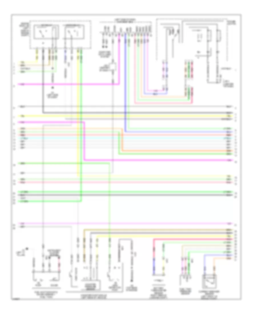
2.4L Hybrid, Engine Performance Wiring Diagram (1 of 7) for Toyota Camry SE 2011
 https://portal-diagnostov.com/license.html
Automotive Electricians Portal FZCO
Automotive Electricians Portal FZCO
https://portal-diagnostov.com/license.html
https://portal-diagnostov.com/license.html
Automotive Electricians Portal FZCO
Automotive Electricians Portal FZCO
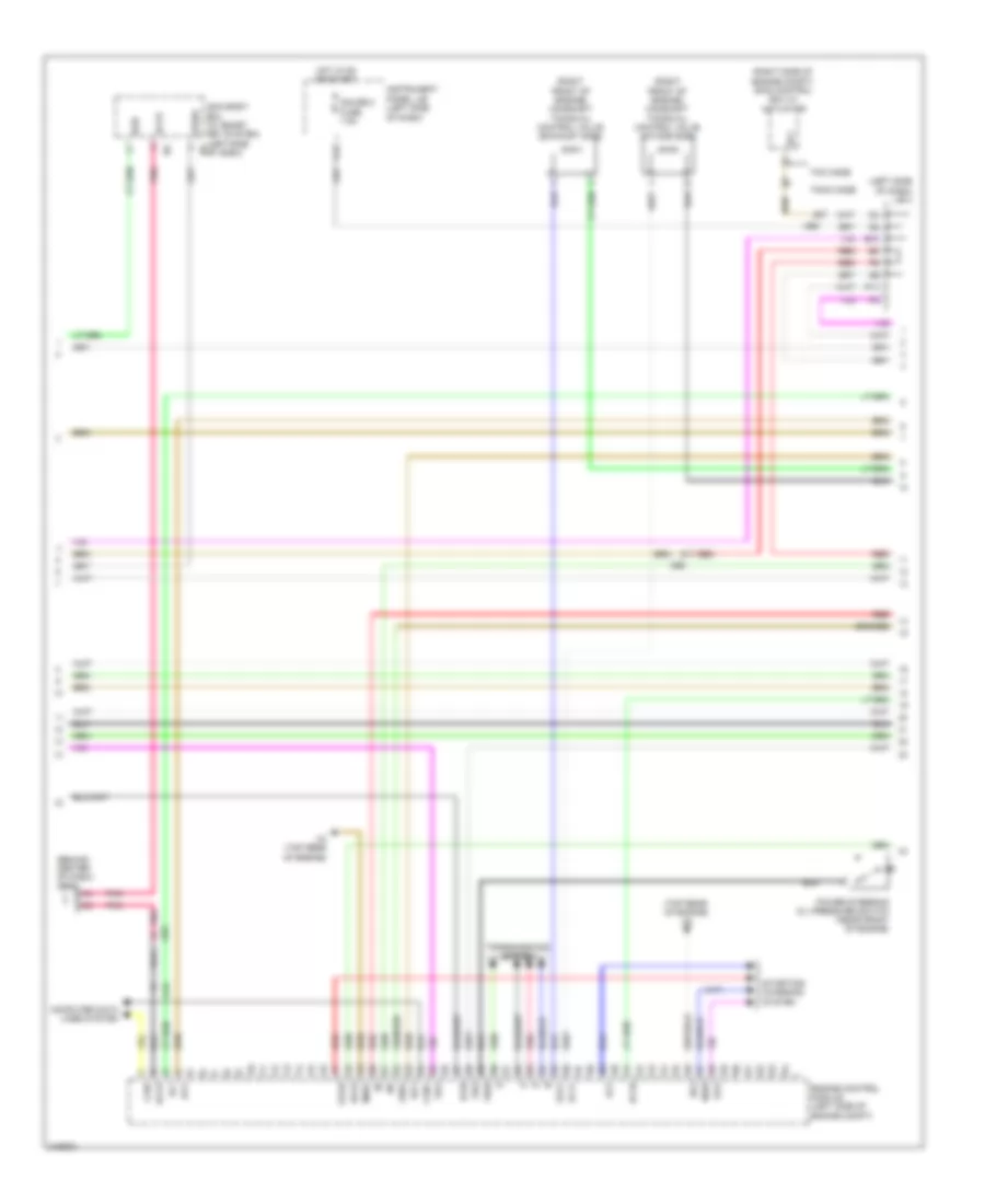
List of elements for 2.4L Hybrid, Engine Performance Wiring Diagram (1 of 7) for Toyota Camry SE 2011:
- (left side of dash)
- +b1
- +b2
- +bm
- A3 (left side of dash)
- A41
- A42
- A58
- A61
- Ae5
- Ae6
- Air conditioning system
- Anti-theft system
- Batt
- Canh
- Canl
- Ccv2
- Computer data lines system
- Cooling fans system
- E40
- Efi main fuse 30a
- Engine room r/b (left side of engine compt)
- Etcs fuse 10a
- Exterior lights system
- Fanh
- Fanl
- Fctl
- Fuel
- Fuo
- G12
- Gauge 2 fuse 7.5a
- Hot at all times
- Hot in on or start
- Hybrid vehicle control ecu (right rear of engine compt)
- Igct 2 fuse 10a
- Igct fuse 30a
- Igct relay
- Ign fuse 10a
- Igsw
- Ilk
- Imi
- Imo
- Instrument panel j/b
- Iwp
- J/c a41 & a42 (behind a41
- J/c a41 & a42 (behind left side of dash)
- J/c a58 & e40 (behind left side of dash)
- J/c n28 (left rear of vehicle)
- Kn1
- Left side of dash)
- Lido
- Lst1
- Lst2
- Mpmp
- Na1
- Oa1
- Pnk
- Rdy
- Red
- Sio
- Smrb
- Spdi
- St1-
- St2
- Stop fuse 10a
- Stop lamp switch (brake pedal assembly)
- Stp
- Tach
- Trunk, tailgate, fuel doors system
- Vlo
- Vpmp
- Vsv (fuel vapour- containment valve) (near fuel tank)
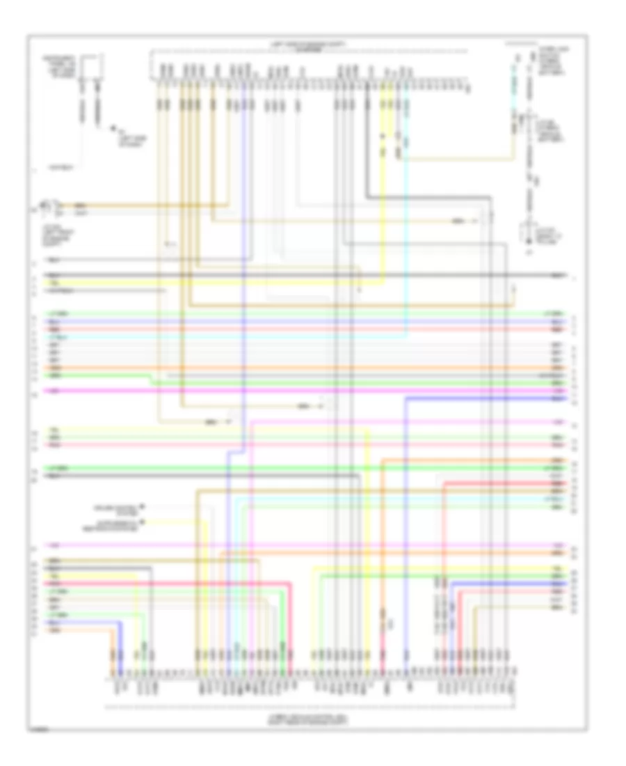
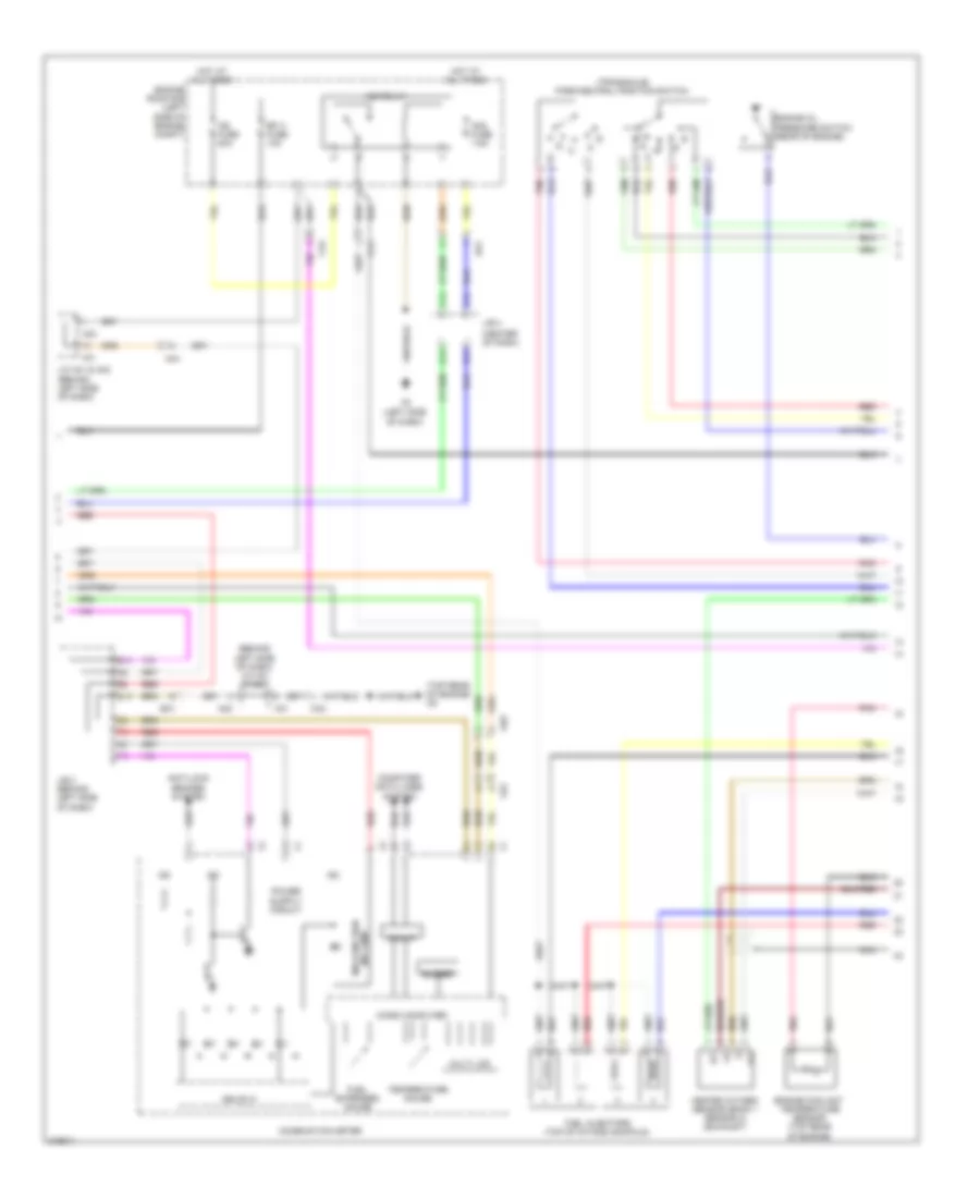
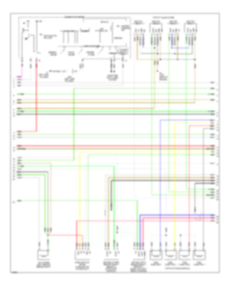
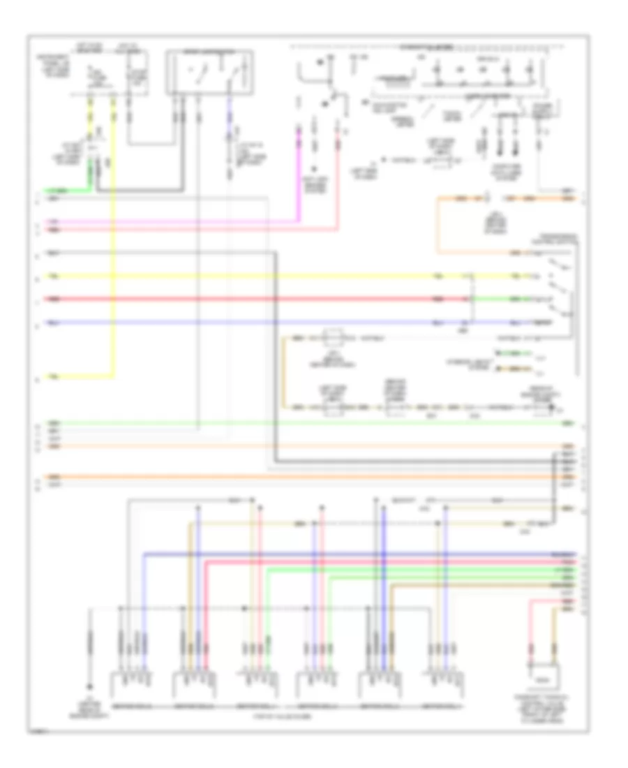
2.4L Hybrid, Engine Performance Wiring Diagram (2 of 7) for Toyota Camry SE 2011
List of elements for 2.4L Hybrid, Engine Performance Wiring Diagram (2 of 7) for Toyota Camry SE 2011:
- (center of dash)
- (left side of dash) main body ecu
- A3 (left side of dash)
- Am2
- Battery thermometer sensor (right rear of luggage compt)
- C/opn relay
- C6 (top rear of engine)
- Ca2
- Ca3
- Canh
- Canister pressure sensor
- Canister pump module (left rear of vehicle)
- Canl
- Computer data lines system
- Current breaker sensor (left front of engine compt)
- D12
- E10
- E11
- E12
- E13
- Efi relay
- Engine room j/b (left side of engine compt)
- Fuel suction pump & gauge assembly (fuel tank)
- Fuel tank pressure sensor
- G11
- Gauge
- Gnd
- Ig2d
- Inds
- Indw
- Instrument cluster system
- J/b 4
- J/b 4 (center of dash)
- Leak detection pump
- N1 (left "c" pillar)
- Na1
- Oa1
- Pnk
- Power switch
- Ptnk
- Pump
- Rdy
- Red
- Ss1
- Ss2
- Ssw1
- Ssw2
- Stsw
- Swil
- Vent valve
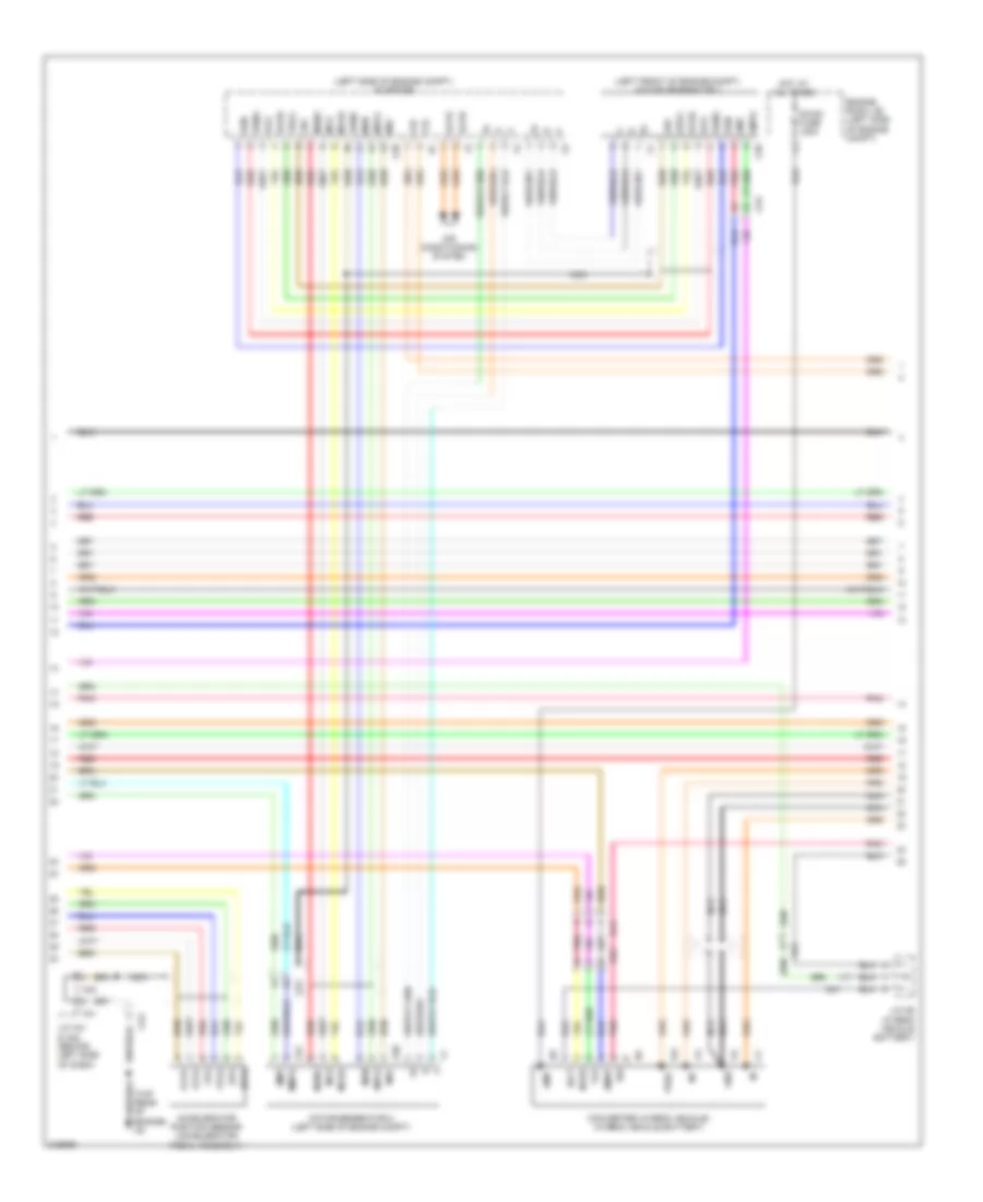
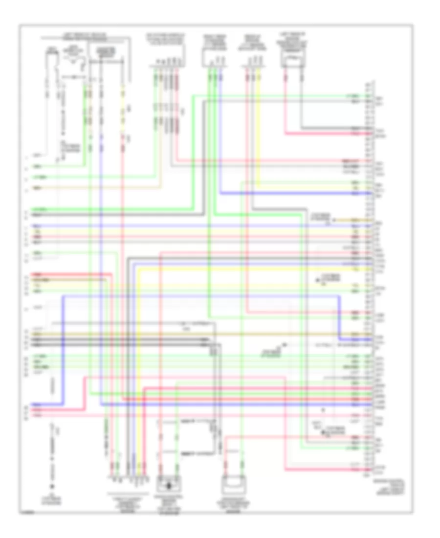
2.4L Hybrid, Engine Performance Wiring Diagram (3 of 7) for Toyota Camry SE 2011
List of elements for 2.4L Hybrid, Engine Performance Wiring Diagram (3 of 7) for Toyota Camry SE 2011:
- (left side of dash)
- (left side of engine compt) inverter
- +b2
- A61
- A62
- Abfs
- As1
- As1g
- Bth+
- Bth-
- Ccs
- Clk+
- Clk-
- Cruise control system
- Drn1
- Drn2
- Drn3
- Drn4
- Drn5
- Drn8
- Eib
- Ep1
- Ep2
- Eppm
- Eptk
- G10
- Gmt
- Gmtg
- Gnd
- Gnd1
- Gnd2
- Hsdn
- Htm+
- Htm-
- Hybrid vehicle control ecu (right rear of engine compt)
- Ilk
- Ilki
- Ilko
- Instrument panel j/b (left side of dash)
- Inter lock switch (hybrid vehicle battery)
- J/c a43 (left front of engine compt)
- J/c n6 (hybrid vehicle battery)
- J/c o21 (right "c" pillar)
- Mmt
- Mmtg
- Mrel
- Mth+
- Mth-
- Nodd
- Oa1
- On1
- Pnk
- Ppmp
- Ptnk
- Red
- Req+
- Req-
- Smrg
- Smrp
- Thb
- Vcp1
- Vcp2
- Vcpp
- Vcpt
- Vpa
- Vpa2
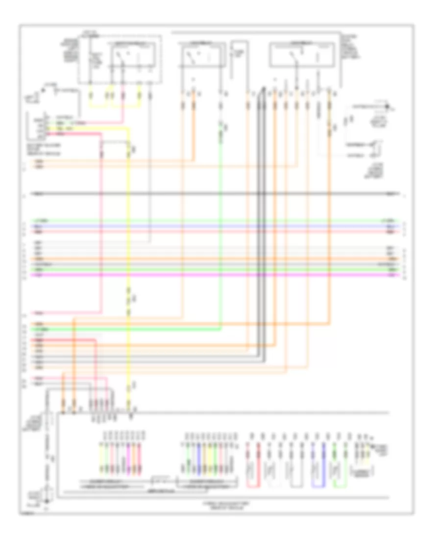
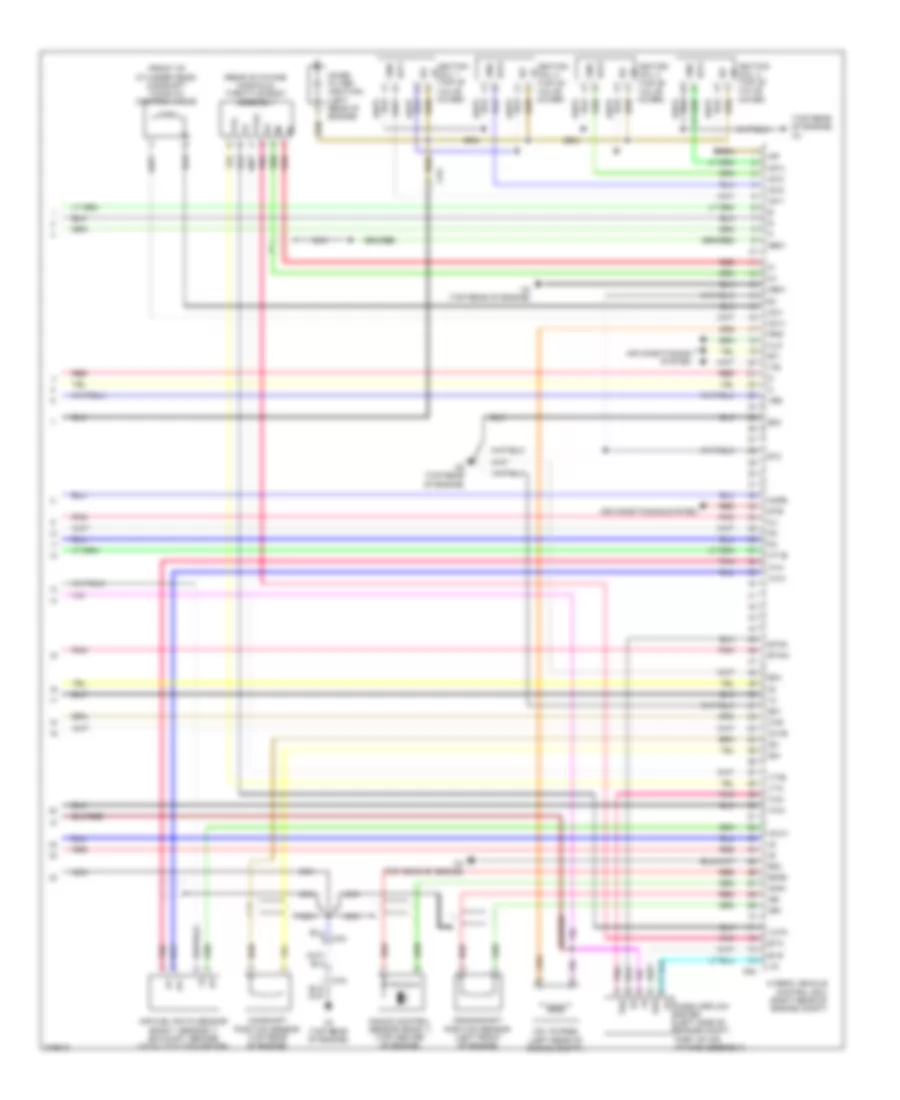
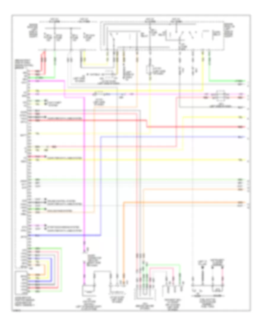
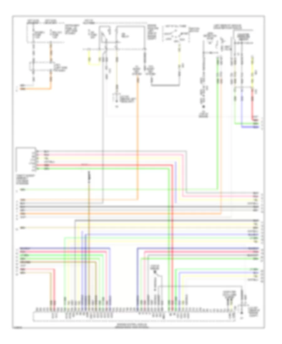
2.4L Hybrid, Engine Performance Wiring Diagram (4 of 7) for Toyota Camry SE 2011
List of elements for 2.4L Hybrid, Engine Performance Wiring Diagram (4 of 7) for Toyota Camry SE 2011:
- (left front of engine compt) motor generator 1
- (left side of engine compt) inverter
- (top rear of engine) c6
- A41
- A42
- Accelerator position sensor (accelerator pedal assembly)
- Acpb
- Acpe
- Air conditioning system
- Amd
- C58
- C59
- C60
- C61
- Ca2
- Ca3
- Cbi
- Cei
- Converter (hybrid vehicle) (hybrid vehicle battery)
- Dc/dc fuse 120a
- Drn6
- Engine room j/b (left side of engine compt)
- Epa
- Epa2
- Gcs
- Gcsg
- Gmt
- Gmtg
- Gnd
- Grf
- Grfg
- Gsn
- Gsng
- Hot at all times
- Idh
- Igct
- In+
- In-
- J/c a41 & a42 (behind left side of dash)
- J/c n6 (hybrid vehicle battery)
- Mcs
- Mcsg
- Mmt
- Mmtg
- Motor generator 2 (left side of engine compt)
- Mrf
- Mrfg
- Msn
- Msng
- Nca
- Nodd
- Oa1
- On1
- Pnk
- Prec
- Red
- Smrp
- Vcp2
- Vcpa
- Vlo
- Vpa
- Vpa2
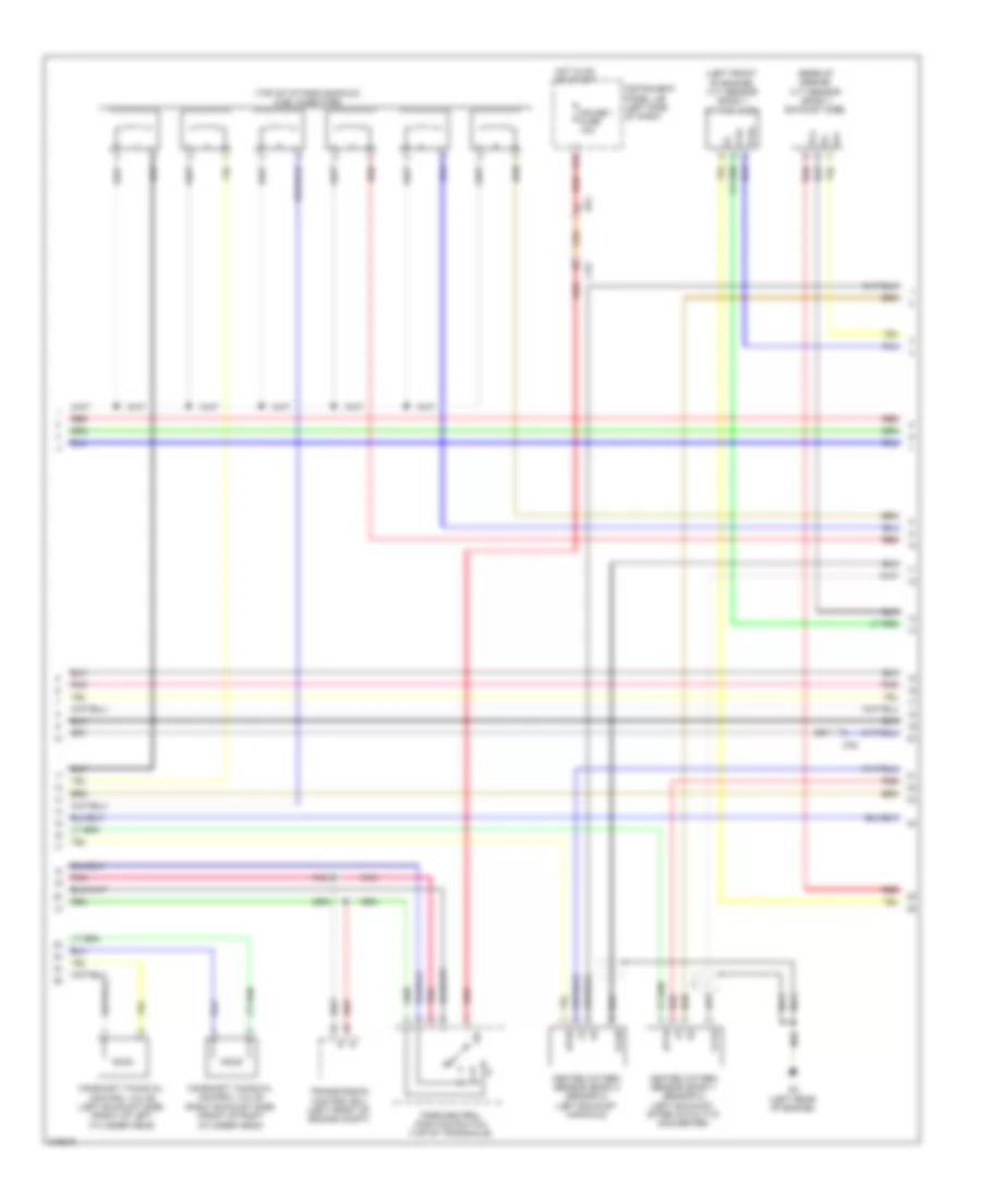
2.4L Hybrid, Engine Performance Wiring Diagram (5 of 7) for Toyota Camry SE 2011
List of elements for 2.4L Hybrid, Engine Performance Wiring Diagram (5 of 7) for Toyota Camry SE 2011:
- Batt fan fuse 10a
- Batt fan relay
- Battery blower motor (rear of vehicle)
- Battery smart unit
- Bth+
- Bth-
- Busber module 1
- Busber module 2
- Current sensor
- En2
- Engine room r/b (left side of engine compt)
- Eo2
- Fuse 15a
- Gb0
- Gb1
- Gb2
- Gb3
- Gc0
- Gc0 r3
- Gib
- Gnd
- Gnd0
- Hot at all times
- Hybrid vehicle battery
- Hybrid vehicle battery (rear of vehicle)
- Idh
- Ig0
- Igc1
- J/c n29
- J/c n6 (hybrid vehicle battery)
- J/c o21 (right "c" pillar)
- Main relay
- N1 (left "c" pillar)
- Na1
- Nca
- Oa1
- On1
- Pnk
- Red
- Service plug
- Si0
- System main relay (hybrid vehicle battery)
- Tb0
- Tb1
- Tb2
- Tb3
- Tc0
- Vc1
- Vc10
- Vc11
- Vc12
- Vc13
- Vc14
- Vc15
- Vc16
- Vc17
- Vc2
- Vc3
- Vc4
- Vc5
- Vc6
- Vc7
- Vc8
- Vc9
- Vib
- Vim
- Vm0
2.4L Hybrid, Engine Performance Wiring Diagram (6 of 7) for Toyota Camry SE 2011
List of elements for 2.4L Hybrid, Engine Performance Wiring Diagram (6 of 7) for Toyota Camry SE 2011:
- (behind left side of dash) j/c a41 & a42
- (center of dash)
- (left side of dash)
- (top rear of engine) c6
- (transaxle) park/neutral position switch
- A41
- A42
- Ae5
- Am2 fuse 7.5a
- Anti-lock brakes system
- B10
- Buzzer
- Ca1
- Ca2
- Ca3
- Can i/f
- Combination meter
- Computer data lines system
- D10
- Drive ic
- E10
- E12
- Ea1
- Efi 3 fuse 10a
- Engine coolant temperature sensor (top rear of engine)
- Engine oil pressure switch (rear of engine)
- Engine room r/b (left side of engine compt)
- Fe3
- Fuel expenses gauge
- Fuel injectors (top of intake manifold)
- Heated oxygen sensor (bank 1 sensor 2) (exhaust)
- Hot at all times
- Ig2
- Ig2 fuse 20a
- Ig2 relay
- J/b 3 (behind left side of dash)
- J/b 4
- J/c a41 & a42 (behind left side of dash)
- M10
- M12
- Malfunction ind lamp
- Micro computer
- Multi lcd
- Na1
- Nca
- Pnk
- Red
- Temperature gauge
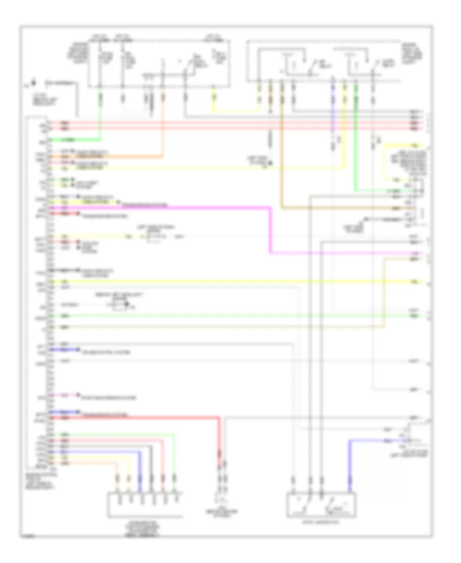
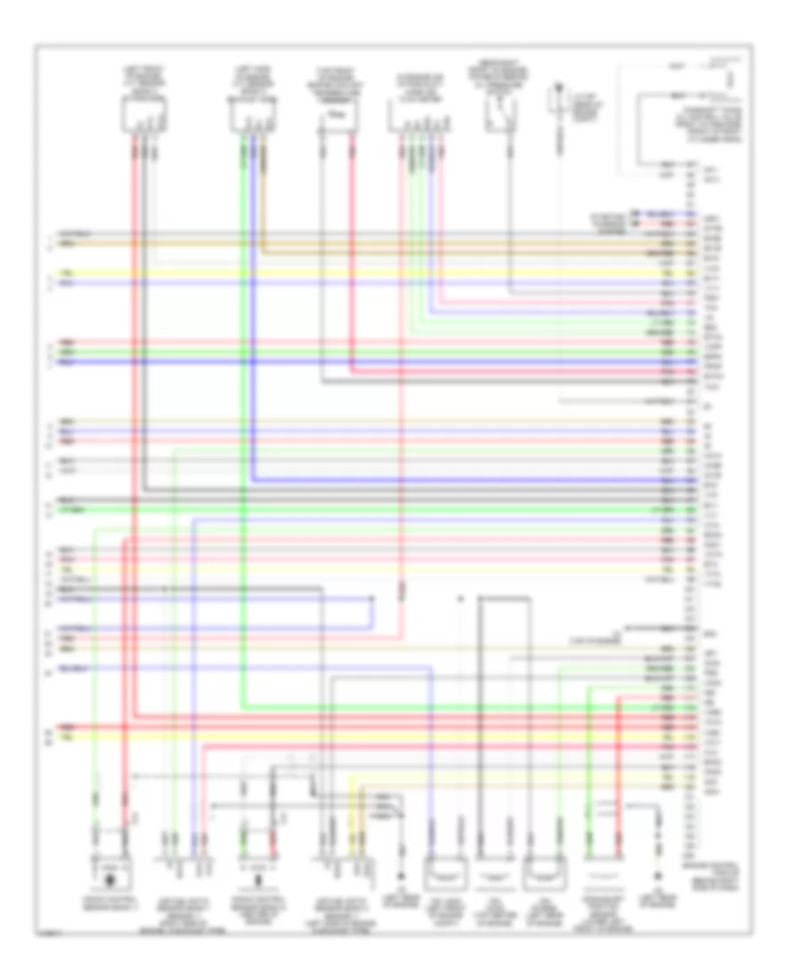
2.4L Hybrid, Engine Performance Wiring Diagram (7 of 7) for Toyota Camry SE 2011
List of elements for 2.4L Hybrid, Engine Performance Wiring Diagram (7 of 7) for Toyota Camry SE 2011:
- (front of cylinder head) camshaft timing oil control valve
- (rear of intake manifold) throttle body assembly
- (top rear of engine) c4
- +bs
- A1a+
- A1a-
- Af+
- Af-
- Air conditioning system
- Air fuel ratio sensor (bank 1 sensor 1) (exhaust, before catalytic converter)
- C4 (top rear of engine)
- C6 (top rear of engine)
- C64
- Ca3
- Camshaft position sensor (top rear of engine)
- Clk
- Crankshaft position sensor (left front of engine)
- E01
- E02
- E03
- E04
- E12
- E2g
- Eknk
- Eta
- Etha
- Ethw
- Eti
- Evg
- G2+
- G2-
- Ge01
- Gnd
- Ha1a
- Ht1b
- Hybrid vehicle control ecu (right rear of engine compt)
- Igf
- Ignition coil 1 (top of valve cover)
- Ignition coil 2 (top of valve cover)
- Ignition coil 3 (top of valve cover)
- Ignition coil 4 (top of valve cover)
- Igt1
- Igt2
- Igt3
- Igt4
- Ite
- Knk1
- Knock control sensor (bank 1) (top center of engine)
- Mass airflow meter (left side of engine compt, part of air intake assembly)
- Me01
- Mops
- Nca
- Ne+
- Ne-
- Noise filter (ignition) (left rear of engine)
- O1b-
- Oc1+
- Oc1-
- Ox1b
- Pnk
- Prg
- Red
- Stb
- Tha
- Thw
- Vcta
- Vsv (purge) (left rear of engine compt)
- Vta
- Vta2
2.5L
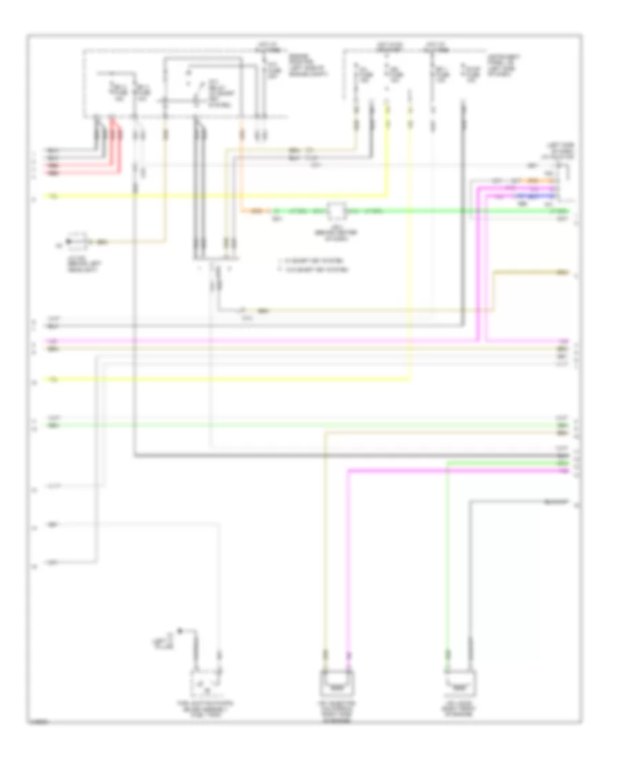
2.5L, Engine Performance Wiring Diagram (1 of 5) for Toyota Camry SE 2011
List of elements for 2.5L, Engine Performance Wiring Diagram (1 of 5) for Toyota Camry SE 2011:
- (a58, a41 & a42: left side of dash) (e40: behind right side of dash) j/c a58, e40, a41 & a42
- (behind left headlight) j/c a43
- (left side of dash)
- (left side of dash) a3
- +b2
- +bm
- A24
- A3 (left side of dash)
- A41
- A42
- A58
- Accelerator position sensor (accelerator pedal assembly)
- Ae5
- Anti-theft system
- Batt
- C/opn relay
- Ca2
- Canh
- Canl
- Ccs
- Computer data lines system
- Cooling fans system
- Cruise control system
- D12
- E10
- E11
- E12
- E13
- E40
- Efi 2 fuse 30a
- Efi main fuse 30a
- Efi main relay
- Efi relay
- Engine control module (left side of engine compt)
- Engine room j/b (left side of engine compt)
- Engine room r/b (left side of engine compt)
- Epa
- Epa2
- Etcs fuse 10a
- Fanh
- Fanl
- Hot at all times
- Igsw
- Imi
- Imo
- J/b 4 (behind center of dash)
- J/c a41
- J/c a41 & a42 (left side of dash)
- J/c a43 (behind left headlight)
- Mpmp
- Mrel
- Na1
- Pnk
- Red
- Sftd
- Sftu
- Spd
- St1-
- Sta
- Starting/charging system
- Stop lamp switch
- Stp
- Stsw
- Tach
- Transmissions system
- Vcp2
- Vcpa
- Vpa
- Vpa2
- Vpmp
2.5L, Engine Performance Wiring Diagram (2 of 5) for Toyota Camry SE 2011
List of elements for 2.5L, Engine Performance Wiring Diagram (2 of 5) for Toyota Camry SE 2011:
- (left side of dash) j/c a41 & a42
- (left side of engine compt)
- A41
- A42
- Ae5
- Ca1
- Ca2
- Ca3
- E10
- Ea1
- Efi 1 fuse 10a
- Efi 2 fuse 15a
- Efi 3 fuse 10a
- Engine room r/b
- Fuel suction pump & gauge assembly (fuel tank)
- Hot at all times
- Hot in on or start
- Ig 2 fuse 20a
- Ig 2 relay (w/ smart key system)
- Ign fuse 10a
- Inj fuse 15a
- Instrument panel j/b (left side of dash)
- J/b 4 (behind center of dash)
- J/c a43 (behind left headlight)
- M10
- N1 (left "c" pillar)
- Na1
- Red
- Stop fuse 10a
- Vsv (acis) (right front of engine)
- Vsv (ejector) (california) (right side of engine)
- W/ smart key system
- W/o smart key system
2.5L, Engine Performance Wiring Diagram (3 of 5) for Toyota Camry SE 2011
List of elements for 2.5L, Engine Performance Wiring Diagram (3 of 5) for Toyota Camry SE 2011:
- (a/t)
- (behind center of dash) j/b 4
- (left side of dash) j/b 3
- (right front of engine) camshaft timing oil control valve (exhaust side)
- (right front of engine) camshaft timing oil control valve (intake side)
- (right side of engine compt) skid control ecu w/ actuator
- (top rear of engine)
- Accr
- Acis
- Ae5
- Ae6
- Alt
- B10
- C4 (top rear of engine)
- Ca2
- Can+
- Can-
- Computer data lines system
- Engine control module (left side of engine compt)
- Eo4
- G12
- Gauge 2 fuse 7.5a
- Ge01
- Ha1a
- Hot in on or start
- Ht1b
- Ia1+
- Ia1-
- Ig2d
- Igf1
- Instrument panel j/b (left side of dash)
- Main body ecu (w/ smart key system) (left side e9 of dash)
- Me01
- Nsw
- Oc1+
- Oe1+
- P11
- Pbv
- Pnk
- Power steering oil pressure switch (near front of engine)
- Prg
- Psw
- Red
- Sp1
- Sta
- Star
- Starting/ charging system
- Stsw
- Tmc made
- Tmmk made
- Transmissions system
2.5L, Engine Performance Wiring Diagram (4 of 5) for Toyota Camry SE 2011
List of elements for 2.5L, Engine Performance Wiring Diagram (4 of 5) for Toyota Camry SE 2011:
- (top of intake manifold)
- (top of valve cover)
- +b(dome)
- A1a+
- A1a-
- Air fuel ratio sensor (bank 1 sensor 1) (near top right rear of engine)
- Buzzer
- C4 (top rear of engine)
- Can i/f
- Combination meter
- Computer data lines system
- Drive ic
- E2g
- F1 (left side of dash)
- Fuel injector 1
- Fuel injector 2
- Fuel injector 3
- Fuel injector 4
- Gnd
- Ha1a
- Heated oxygen sensor (bank 1 sensor 2) (in exhaust manifold)
- Ht1b
- Ig2
- Igf
- Ignition coil 1
- Ignition coil 2
- Ignition coil 3
- Ignition coil 4
- Igt1
- Igt2
- Igt3
- Igt4
- J/b 3 (left side of dash)
- Lcd a/t position
- Malfunction ind lamp
- Mass air flow meter (in engine air intake duct)
- Master warning ind
- Micro computer
- Multi lcd
- Nca
- Ox1b
- Pnk
- Red
- Speedo- meter
- Tacho- meter
- Temper- ature
- Tha
- Vsv (purge) (left rear of engine compt)
2.5L, Engine Performance Wiring Diagram (5 of 5) for Toyota Camry SE 2011
List of elements for 2.5L, Engine Performance Wiring Diagram (5 of 5) for Toyota Camry SE 2011:
- (left rear of engine) engine coolant temperature sensor
- (left rear of vehicle) canister pump module
- (on intake manifold) intake air control valve actuator
- (rear of engine) vvt sensor (exhaust side)
- (right rear of engine) vvt sensor (intake side)
- (top center of engine)
- (top rear of engine) c4
- (top rear of engine) c6
- A1a+
- A1a-
- C24
- C6 (top rear of engine)
- Ca2
- Ca3
- Canister pressure sensor
- Ch1
- Crankshaft position sensor (left front of engine)
- E01
- E02
- E2g
- Eia1
- Eknk
- Engine control module (left side of engine compt)
- Eo3
- Eppm
- Eta
- Etha
- Ethw
- Ev1+
- Ev1-
- G2+
- G2-
- Gnd
- Iac1
- Igt1
- Igt2
- Igt3
- Igt4
- Knk1
- Knock control sensor (bank 1)
- Leak detection pump
- Na1
- Nca
- Ne+
- Ne-
- O1b-
- Oc1-
- Oe1-
- Out
- Ox1b
- Pnk
- Ppmp
- Red
- Tha
- Throttle body assembly (top rear of engine)
- Thw
- Vc2
- Vce1
- Vcia
- Vcpp
- Vcta
- Vcv1
- Vdd
- Vent valve
- Vta
- Vta2
- Vve+
- Vve-
- Vvi+
- Vvi-
3.5L
3.5L, Engine Performance Wiring Diagram (1 of 5) for Toyota Camry SE 2011
List of elements for 3.5L, Engine Performance Wiring Diagram (1 of 5) for Toyota Camry SE 2011:
- (behind right side of dash) engine control module
- (left "c" pillar) n1
- (left side of dash)
- (left side of dash) a3
- +b2
- +bm
- A/f fuse 20a
- A/f relay
- A3 (left side of dash)
- A41
- A42
- A55
- A56
- Accelerator position sensor (accelerator pedal assembly)
- Accr
- Ae5
- Aicv
- Anti-theft system
- B10
- Batt
- C/opn relay
- Ca2
- Canh
- Canl
- Ccs
- Computer data lines system
- Cooling fans system
- Cruise control system
- D12
- E10
- E11
- E12
- E13
- Ea1
- Efi 1 fuse 10a
- Efi 2 fuse 15a
- Efi 3 fuse 10a
- Efi main fuse 30a
- Efi relay
- Engine room j/b (left side of engine compt)
- Engine room r/b (left side of engine compt)
- Epa
- Epa2
- Etcs fuse 10a
- Fuel suction pump & gauge assembly (fuel tank)
- Gauge
- Hot at all times
- Ig2d
- Igsw
- Imi
- Imo
- Instrument cluster system
- J/b 3 (left side of dash)
- J/b 4 (behind center of dash)
- J/c a41
- J/c a41 & a42 (left side of dash)
- J/c a41 (left side of dash)
- M10
- Main body ecu (w/ smart key system) (left side of dash)
- Mpmp
- Mrel
- Na1
- Pnk
- Pump
- Red
- Rfc
- Sftd
- Sftu
- Short connector a56 & a57 (right side a57 of dash)
- Spd
- St1-
- Sta
- Starting/charging system
- Stp
- Stsw
- Tach
- Vcp2
- Vcpa
- Vpa
- Vpa2
- Vpmp
- Vsv (air intake control) (left of engine compt, in air intake)
3.5L, Engine Performance Wiring Diagram (2 of 5) for Toyota Camry SE 2011
List of elements for 3.5L, Engine Performance Wiring Diagram (2 of 5) for Toyota Camry SE 2011:
- (behind center of dash) j/c e48
- (left side of dash)
- (left side of dash) j/b 3
- (rear of engine compt) j/c c57
- (top of valve cover)
- A11
- A42
- A58
- Ae5
- Anti-lock brakes system
- C12
- C7 (center rear of engine compt)
- Ca3
- Camshaft timing oil control valve (left intake side) (front of left cylinder head)
- Can i/f
- Combination meter
- Computer data lines system
- D10
- Drive ic
- E40
- Ea1
- Gnd
- H10
- Hot at all times
- Hot in on or start
- Ig2
- Igf
- Ign fuse 10a
- Ignition coil 1
- Ignition coil 2
- Ignition coil 3
- Ignition coil 4
- Ignition coil 5
- Ignition coil 6
- Igt1
- Igt2
- Igt3
- Igt4
- Igt5
- Igt6
- Ill+
- Ill-
- Instrument panel j/b
- Interior lights system
- J/b 4 (behind center of dash)
- J/c a40 & a58 (left side of dash)
- J/c a41 & a42 (left side a41 of dash)
- Malfunction ind lamp
- Micro computer
- Multi lcd
- Pnk
- Red
- Sftd
- Sftu
- Speedo- meter
- Stop fuse 10a
- Stop lamp switch
- Tacho- meter
- Transmission control switch
3.5L, Engine Performance Wiring Diagram (3 of 5) for Toyota Camry SE 2011
List of elements for 3.5L, Engine Performance Wiring Diagram (3 of 5) for Toyota Camry SE 2011:
- (left rear of vehicle) canister pump module
- (left side of dash)
- (top of engine)
- (top of engine) c4
- Acc
- Acm
- C55
- Ca1
- Ca2
- Ca3
- Can+
- Can-
- Canister pressure sensor
- Computer data lines system
- Ea1
- Ecu ig 2 fuse 7.5a
- Engine control module (behind right side of dash)
- Engine room r/b (left side of engine compt)
- Eo1
- Eo2
- Eo4
- Eo5
- F19
- G12
- Gauge 2 fuse 7.5a
- Geo1
- Hot at all times
- Hot in on or start
- Ht1b
- Ht2b
- Ig2 fuse 20a
- Ig2 relay
- Ignition switch
- Igt1
- Igt2
- Igt3
- Igt4
- Igt5
- Igt6
- Instrument panel j/b (left side of dash)
- J/b 3
- J/c a43 (behind left headlight)
- J/c c57 (rear of engine compt)
- Leak detection pump
- Lock
- Meo1
- Na1
- Nca
- Oc2+
- Oc2-
- Oe1+
- Oe1-
- Oe2+
- Oe2-
- Off
- Pnk
- Red
- Run
- Start
- Throttle body assembly (top rear of engine)
- Vent valve
- Vta
- Vta2
- W/ smart key system
- W/o smart key system
3.5L, Engine Performance Wiring Diagram (4 of 5) for Toyota Camry SE 2011
List of elements for 3.5L, Engine Performance Wiring Diagram (4 of 5) for Toyota Camry SE 2011:
- (left front of engine) vvt sensor (bank 1 intake side)
- (rear of engine) vvt sensor (bank 1 exhaust side)
- (top of intake manifold) fuel injectors
- C5 (left rear of engine)
- Ca2
- Camshaft timing oil control valve (left exhaust side) (front of left cylinder head)
- Camshaft timing oil control valve (right exhaust side) (front of right cylinder head)
- Ea1
- Ex+
- Ex-
- Gauge 1 fuse 10a
- H16
- Heated oxygen sensor (bank 1 sensor 2) (left exhaust, after catalytic converter)
- Heated oxygen sensor (bank 2 sensor 2) (left exhaust manifold)
- Hot in on or start
- Ht1b
- Ht2b
- Instrument panel j/b (left side of dash)
- Nca
- Ox1b
- Ox2b
- Park/neutral position switch (top of transaxle)
- Pnk
- Red
- Transmission control ecu (left front of engine compt)
- Vc2
- Vvr+
- Vvr-
3.5L, Engine Performance Wiring Diagram (5 of 5) for Toyota Camry SE 2011
List of elements for 3.5L, Engine Performance Wiring Diagram (5 of 5) for Toyota Camry SE 2011:
- (in engine air intake duct) mass air flow meter
- (left front of engine) vvt sensor (bank 2 intake side)
- (left side of engine) vvt sensor (bank 2 exhaust side)
- (near right front of engine) power steering oil pressure switch
- (top front of engine) engine coolant temperature sensor
- A1a+
- A1a-
- A2a+
- A2a-
- Acis
- Air fuel ratio sensor (bank 1 sensor 1) (right side of engine, in exhaust pipe)
- Air fuel ratio sensor (bank 2 sensor 1) (left side of engine, in exhaust pipe)
- C4 (top of engine)
- C5 (left rear of engine)
- C55
- Camshaft timing oil control valve (right intake side) (front of right cylinder head)
- Crankshaft position sensor (lower left front of engine)
- Cv1
- E2g
- Ekn2
- Eknk
- Engine control module (behind right side of dash)
- Eo3
- Eppm
- Eta
- Etha
- Ethw
- Ev1+
- Ev1-
- Ev2+
- Ev2-
- Ex+
- Ex-
- Ex1b
- Ex2b
- Ha1a
- Ha2a
- Igf1
- J/c c57 (rear of engine compt)
- Knk1
- Knk2
- Knock control sensor (bank 1)
- Knock control sensor (bank 2) (center of engine)
- Nca
- Ne+
- Ne-
- Nsw
- Oc1+
- Oc1-
- Ox1b
- Ox2b
- Pnk
- Ppmp
- Prg
- Psw
- Red
- Star
- Starting/ charging system
- Tha
- Thw
- Vc2
- Vce1
- Vce2
- Vcpp
- Vcta
- Vcv1
- Vcv2
- Vsv (acis) (top center of engine)
- Vsv (acm) (left front of engine compt)
- Vsv (purge) (left rear of engine)
- Vta1
- Vta2
- Vv1+
- Vv1-
- Vv2+
- Vv2-
- Vvl+
- Vvl-

 Čeština
 Dansk
Dansk Deutsch
 Ελληνικά
 English
 Español
 Suomi
Suomi Français
 Français
 עברית
עברית Hrvatski
 Magyar
 Italiano
 日本語
日本語 한국어
한국어 Nederlands
 Polski
 Português
 Português
 Română
 Русский
 Slovenčina
 Slovenščina
 Svenska
 Türkçe
 中文 (中国)