ENGINE PERFORMANCE
1.8L
1.8L, Engine Performance Wiring Diagram (1 of 3) for Toyota MR2 2005
 https://portal-diagnostov.com/license.html
Automotive Electricians Portal FZCO
Automotive Electricians Portal FZCO
https://portal-diagnostov.com/license.html
https://portal-diagnostov.com/license.html
Automotive Electricians Portal FZCO
Automotive Electricians Portal FZCO
List of elements for 1.8L, Engine Performance Wiring Diagram (1 of 3) for Toyota MR2 2005:
- (body harn, left door sill) b7
- (body harn, left quarter- panel)
- (dash harn, behind instrument cluster) i4
- (near right door striker)
- A/c system
- Abs
- Acc
- Acmg
- B7 (body harn, left door sill)
- Batt
- C10
- C11
- C12
- Circuit opening relay
- Code
- Combination meter
- Cooling fans system
- Ea (left rear strut tower)
- Efi 1 fuse 15a
- Efi 2 fuse 7.5a
- Efi main relay
- Electronic power steering system
- Engine control module (behind driver's seat, on panel)
- Engine room r/b (left side of engine compt)
- F/ps
- Fan
- Fuel pump (in fuel tank)
- Fusible link block (left front side of engine compt)
- Gauge fuse 7.5a
- Gnd
- Hot at all times
- Hot in on or start
- Hot in start
- If (behind left center of dash, on brace)
- Ig2 fuse 15a
- Ig2 relay
- Ignition switch
- Igsw
- Imld
- Instrument cluster system
- J/b 6 (behind center of dash)
- Ksw
- Lcki
- Lock
- Mil
- Mpx1
- Mpx2
- Mrel
- Nsw
- Power steering system (power steering ecu)
- Pre
- Psct
- Ptnk
- R/b 3 (behind left corner of dash)
- Rxck
- Security indicator light (a/c switch)
- Sil
- Skid control ecu (on left front fenderwell)
- Spd
- St fuse 7.5a
- Sta
- Start
- Starting/ charging system (st relay)
- Std
- Stp
- Tach
- Tbp
- Tra
- Transmission system
- Transponder key amplifier (behind left side of dash, near ignition key cyl)
- Txct
- Unlock warning switch (center of dash)
- Vsv (pressure switching valve) (under rear of vehicle)
- W/ sequential m/t
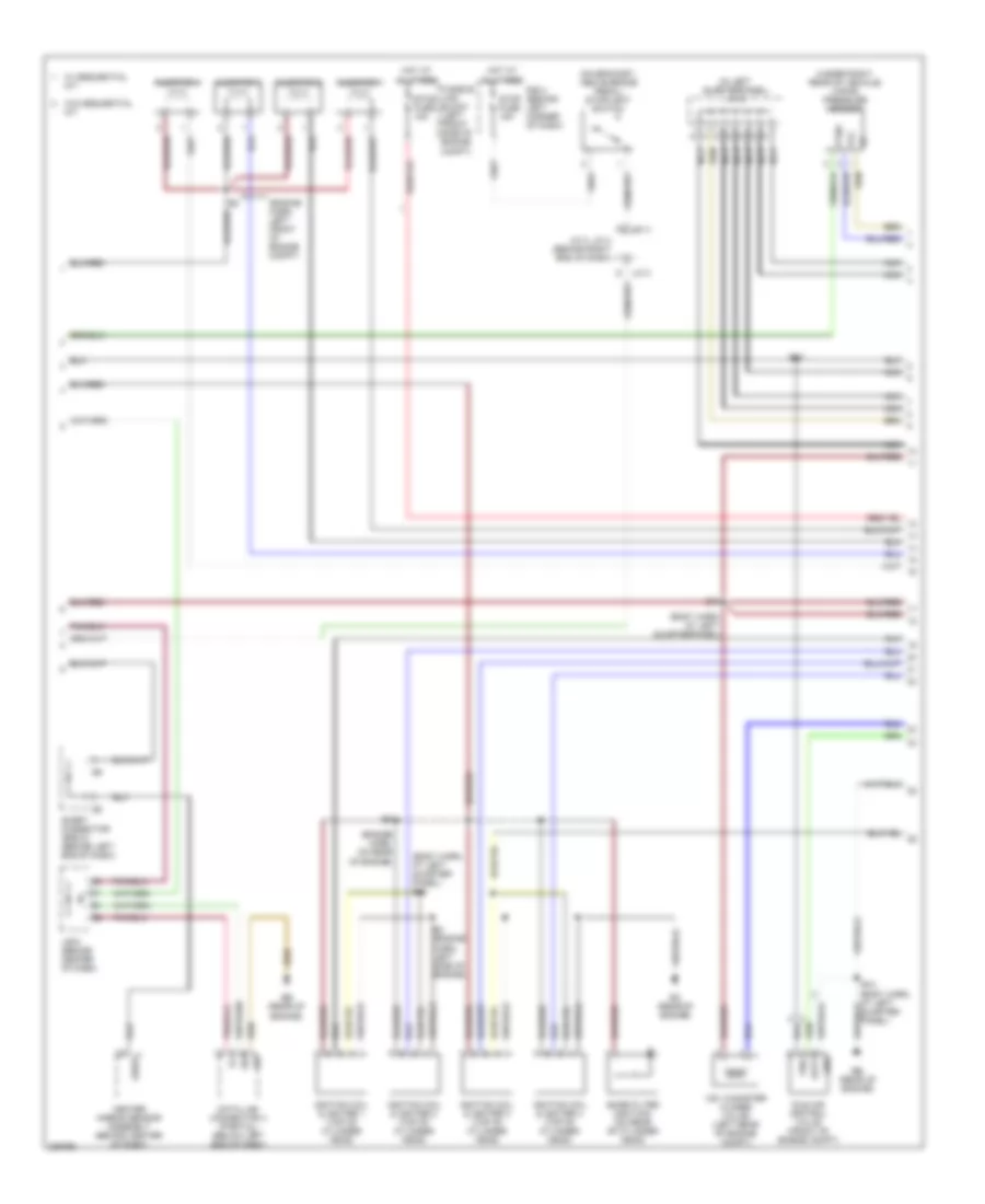
1.8L, Engine Performance Wiring Diagram (2 of 3) for Toyota MR2 2005
List of elements for 1.8L, Engine Performance Wiring Diagram (2 of 3) for Toyota MR2 2005:
- (body harn, at left quarter- panel)
- (body harn, at left quarterpanel)
- (engine harn, left front of engine compt)
- (engine harn, on rear of engine)
- (in left quarterpanel) j/c 5
- (on bracket, above brake pedal) stoplight switch
- (under right rear of vehicle) vapor pressure sensor
- B10
- B12
- Center airbag sensor assembly (behind center of dash)
- D j/c 3
- Data link connector 3 (partial) (below left end of dash)
- Duty
- E4 (engine harn, left side of engine)
- Eb (rear of engine)
- Ec (rear of engine)
- Etcs fuse 15a
- F j/c 4
- Fusible link block (left front side of engine compt)
- Gnd
- Gsw2
- Hot at all times
- Idle air control valve (front of engine compt)
- Ignition coil & igniter 1 (top of cylinder head)
- Ignition coil & igniter 2 (top of cylinder head)
- Ignition coil & igniter 3 (top of cylinder head)
- Ignition coil & igniter 4 (top of cylinder head)
- Injector 1
- Injector 2
- Injector 3
- Injector 4
- J/b 6 (behind center of dash)
- J/c 3, j/c 4 (behind right end of dash)
- Nca
- Nca nca
- Noise filter (ignition) (on rear of cylinder head)
- Ptnk
- R/b 3 (behind left corner of dash)
- Short connector (srs 2) (behind left end of dash)
- Sil
- Stop fuse 15a
- Vcc
- Visc
- Vsv (canister closed valve) (left rear of engine compt)
- W/ sequential m/t
- W/o sequential m/t
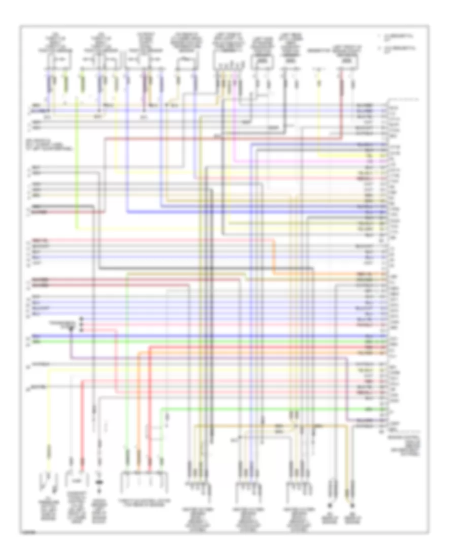
1.8L, Engine Performance Wiring Diagram (3 of 3) for Toyota MR2 2005
List of elements for 1.8L, Engine Performance Wiring Diagram (3 of 3) for Toyota MR2 2005:
- (in front of eng compt) accel position sensor
- (left front of engine compt) vsv (evap)
- (left rear of cylinder head) camshaft position sensor
- (left side of eng compt, on air intake duct) mass airflow meter
- (left side of engine) crankshaft position sensor
- (on rear of cylinder head) engine coolant temperature sensor
- (on throttle body) throttle position sensor
- +bm
- B10
- B12
- Camshaft timing oil control valve (on left front of cylinder head)
- Can+
- Can-
- Ccv
- Cl+
- Cl-
- Csmt
- E01
- E02
- E03
- E2g
- Eb (rear of engine)
- Ec (rear of engine)
- Engine control module (behind driver's seat, on panel)
- Evg
- Evp1
- Generator
- Geo1
- Heated oxygen sensor (bank 1, sensor 1) (on exhaust system)
- Heated oxygen sensor (bank 1, sensor 2) (on exhaust system)
- Heated oxygen sensor (bank 2, sensor 1) (on exhaust system)
- Ht1a
- Ht1b
- Ht2a
- Igf
- Igt1
- Igt2
- Igt3
- Igt4
- Knk1
- Knock sensor (left side of engine block)
- Meo1
- Mops
- Nca
- Nca nca
- Ne+
- Ne-
- Neo
- Ocv+
- Ocv-
- Oil pressure switch (on left side of engine)
- Ox1a
- Ox1b
- Ox2a
- Red
- Rso
- Splice b10 & b12 - (in body harn, at left quarterpanel)
- Tha
- Throttle control motor (top rear of engine)
- Thw
- Transmission system
- Vpa
- Vpa2
- Vta
- Vta2
- W/ sequential m/t
- W/o sequential m/t

 Čeština
 Dansk
Dansk Deutsch
 Ελληνικά
 English
 Español
 Suomi
Suomi Français
 Français
 עברית
עברית Hrvatski
 Magyar
 Italiano
 日本語
日本語 한국어
한국어 Nederlands
 Polski
 Português
 Português
 Română
 Русский
 Slovenčina
 Slovenščina
 Svenska
 Türkçe
 中文 (中国)