ENGINE PERFORMANCE
1.5L
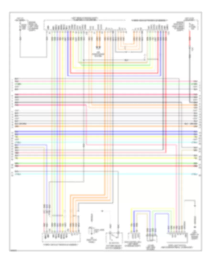
1.5L, Engine Controls Wiring Diagram (1 of 6) for Toyota Prius C 2012
 https://portal-diagnostov.com/license.html
Automotive Electricians Portal FZCO
Automotive Electricians Portal FZCO
https://portal-diagnostov.com/license.html
https://portal-diagnostov.com/license.html
Automotive Electricians Portal FZCO
Automotive Electricians Portal FZCO
List of elements for 1.5L, Engine Controls Wiring Diagram (1 of 6) for Toyota Prius C 2012:
- +b1
- +b2
- A3 (right side of engine compt)
- A4 (left front of engine compt)
- A40
- Ag2
- Batt
- C/ opn relay
- C1 (left rear of engine)
- Ca2
- Canh
- Canl
- Cann
- Canp
- Computer data line system
- Computer data lines system
- Cooling fans system
- Efi main fuse 20a
- Efi main relay
- Egr valve assembly (top right side of engine)
- Egr1
- Egr2
- Egr3
- Egr4
- Eng
- Eng w/ pmp relay
- Engine control module (ecm) (center rear of engine compt)
- Engine room j/b 2 (right rear of engine compt)
- Engine room r/b 2 (left side of engine compt)
- Engine water pump assembly
- Eppm
- Etcs fuse 10a
- Fuse 30a
- Hot at all times
- Hot in on or start
- Igsw
- J/c a50 (left end of dash)
- Meter fuse 7.5a
- Mpmp
- Mrel
- Nwp
- Pgnd
- Pnk
- Ppmp
- Red
- Ref
- Swp
- Tach
- Vcpp
- Vpmp
- W/ pmp
- Wpi
- Wpo
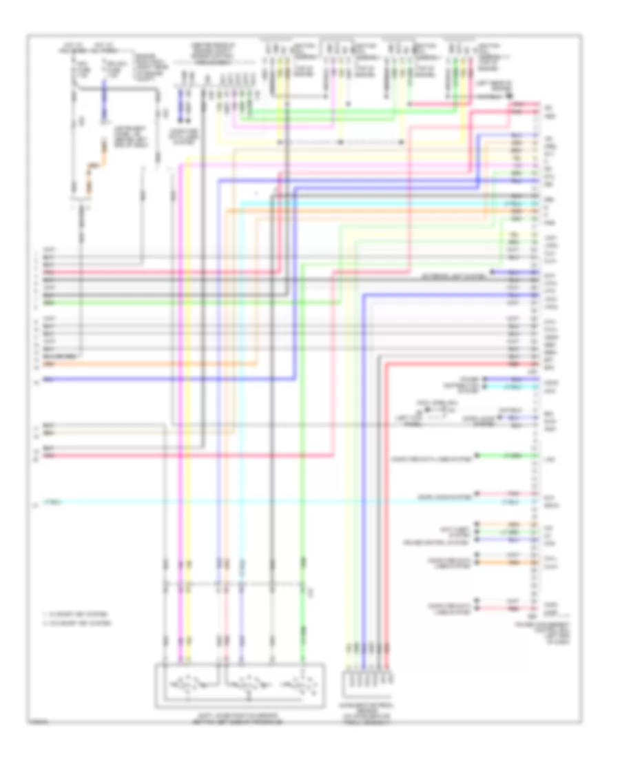
1.5L, Engine Controls Wiring Diagram (2 of 6) for Toyota Prius C 2012
List of elements for 1.5L, Engine Controls Wiring Diagram (2 of 6) for Toyota Prius C 2012:
- (left end of dash) j/c a49
- (left rear of engine)
- (near fuel tank) canister pump module
- (top front of engine)
- +bm
- 1gn fuse 15a
- Am2
- C1 (left rear of engine)
- C10
- C2 (top front of engine)
- Ca2
- Canister pressureure sensor
- E01
- E02
- E04
- Efi fuse 2 10a
- Egr1
- Egr2
- Egr3
- Egr4
- Engine control module (ecm) (center rear of engine compt)
- Engine room r/b 2 (left side of engine compt)
- Fuel suction tube assembly w/ pump & gage
- Ge01
- Ha1a
- Hot in on or start
- Ht1b
- Ig2 fuse 2 10a
- Igt1
- Igt2
- Igt3
- Igt4
- Leak dete- ction pump
- Me01
- Pnk
- Pump
- Red
- Vent valve
1.5L, Engine Controls Wiring Diagram (3 of 6) for Toyota Prius C 2012
List of elements for 1.5L, Engine Controls Wiring Diagram (3 of 6) for Toyota Prius C 2012:
- (center rear of engine compt) engine control module (ecm)
- (left side of engine) throttle body assembly w/ motor
- (top of engine) fuel injector assembly 1
- (top of engine) fuel injector assembly 2
- A37
- B15
- C10
- C12
- C2 (top of front engine)
- Can controller
- Can i/f
- Ce1
- Combination meter assembly
- Computer data lines system
- Cpu
- Eco mode ind
- Ev mode ind
- G7 (center of dash)
- Hot at all times
- Ind lamp malfunction
- Instrument panel j/b (behind left end of dash)
- Knock control sensor (bank 1) (left side of engine)
- Pnk
- Purge vsv (left side of engine)
- Red
- Stop fuse 7.5a
- Vta
- Vta2
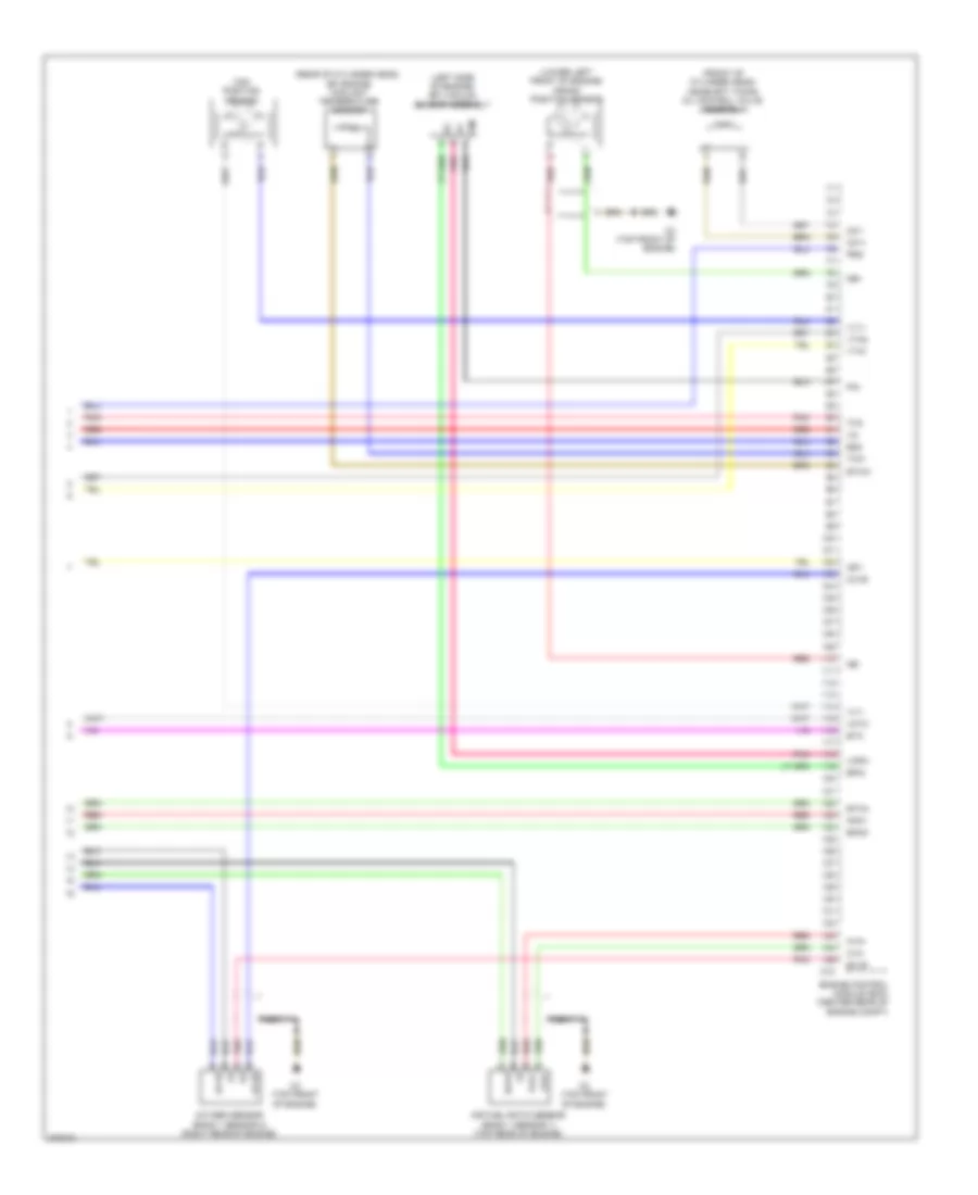
1.5L, Engine Controls Wiring Diagram (4 of 6) for Toyota Prius C 2012
List of elements for 1.5L, Engine Controls Wiring Diagram (4 of 6) for Toyota Prius C 2012:
- (left end of dash) power management control ecu
- (top of engine)
- (top of engine) fuel injector assembly 3
- (top of engine) fuel injector assembly 4
- +b1
- A39
- A4 (left front of engine compt)
- C1 (left rear of engine)
- Ca1h
- Ca1l
- Computer data lines system
- Db1
- Db2
- Ep1
- Ep2
- G57
- G58
- Gnd
- Igf
- Ignition coil assembly 1
- Ignition coil assembly 2
- Ignition coil assembly 3
- Ignition coil assembly 4
- Igt1
- Igt2
- Igt3
- Igt4
- J/c a50 (left end of dash)
- Pnb
- Pnk
- Red
- Spdi
- St1-
- Stop light switch (above brake pedal, on bracket)
- Stp
- Vcp1
- Vcp2
- Vpa1
- Vpa2
1.5L, Engine Controls Wiring Diagram (5 of 6) for Toyota Prius C 2012
List of elements for 1.5L, Engine Controls Wiring Diagram (5 of 6) for Toyota Prius C 2012:
- (left end of dash) j/c a48
- Accelerator pedal sensor (on accelerator pedal assembly)
- C2 (top front of engine)
- Ca1
- E2g
- Ep1
- Ep2
- Intake mass air flow meter sub-assembly (left side of engine)
- N r
- Pnk
- R n
- Red
- Shift lever switch
- Tha
- Vcp1
- Vcp2
- Vpa1
- Vpa2
1.5L, Engine Controls Wiring Diagram (6 of 6) for Toyota Prius C 2012
List of elements for 1.5L, Engine Controls Wiring Diagram (6 of 6) for Toyota Prius C 2012:
- (front of cylinder head) camshaft timing oil control valve assembly
- (left side of engine) efi vacuum sensor assembly
- (lower left front of engine) crank position sensor
- (rear of cylinder head) efi engine coolant temperature sensor
- A1a+
- A1a-
- Air fuel ratio sensor (bank 1 sensor 1) (top rear of engine)
- C10
- C2 (top front of engine)
- Cam position sensor
- E2g
- Eknk
- Engine control module (ecm) (center rear of engine compt)
- Epim
- Eta
- Etha
- Ethw
- Ex1b
- Ha1a
- Ht1b
- Igf1
- Knk1
- Nca
- Ne+
- Ne-
- Oc1+
- Oc1-
- Ox1b
- Oxygen sensor (bank 1 sensor 2) (right rear of engine)
- Pim
- Pnk
- Prg
- Red
- Tha
- Thw
- Vcpm
- Vctc
- Vta1
- Vta2
- Vv1+
- Vv1-
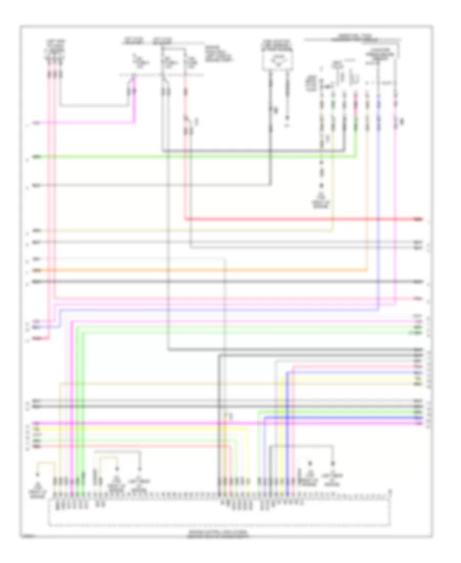
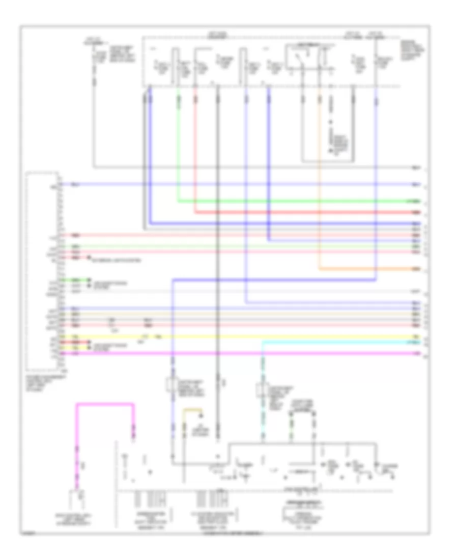
1.5L, Hybrid System Wiring Diagram (1 of 6) for Toyota Prius C 2012
List of elements for 1.5L, Hybrid System Wiring Diagram (1 of 6) for Toyota Prius C 2012:
- (right side of engine compt) a3
- +b2
- 5v +b
- 5v ic
- A37
- A38
- Ag2
- Air conditioning system
- Am1
- B14
- B15
- Batt fan fuse 10a
- Buzzer
- C12
- C36
- Ca1
- Can controller
- Can i/f
- Charge ind
- Clk
- Combination meter assembly
- Computer data lines system
- Cpu
- Drawing circuit
- Eco mode ind
- Ecu-b 2 fuse 7.5a
- Engine room r/b 2 (right rear of engine compt)
- Eti
- Ev mode ind
- Exterior lights system
- G7 (center of dash)
- Gmt
- Gmtg
- Hot at all times
- Hot in on or start
- Hv system indicator drive monitor odo/trip clock
- I/f
- Ig2
- Igct 2 fuse 10a
- Igct 3 fuse 10a
- Igct 4 fuse 10a
- Igct relay
- Ilk
- Instrument panel j/b (behind left end of dash)
- Ite
- Iwp
- Main igct fuse 30a
- Meter fuse 7.5a
- Mmt
- Mmtg
- Niwp
- Nodd
- Opening multi information touch tracer
- Pcu fuse 10a
- Pnk
- Power management control ecu (left end of dash)
- Red
- Segment vfd
- Si0
- Skid control ecu (left rear of engine compt)
- Sp1
- Speedometer fuel shift indicator
- Stb
- Stop fuse 7.5a
- Tft lcd
- Vlo
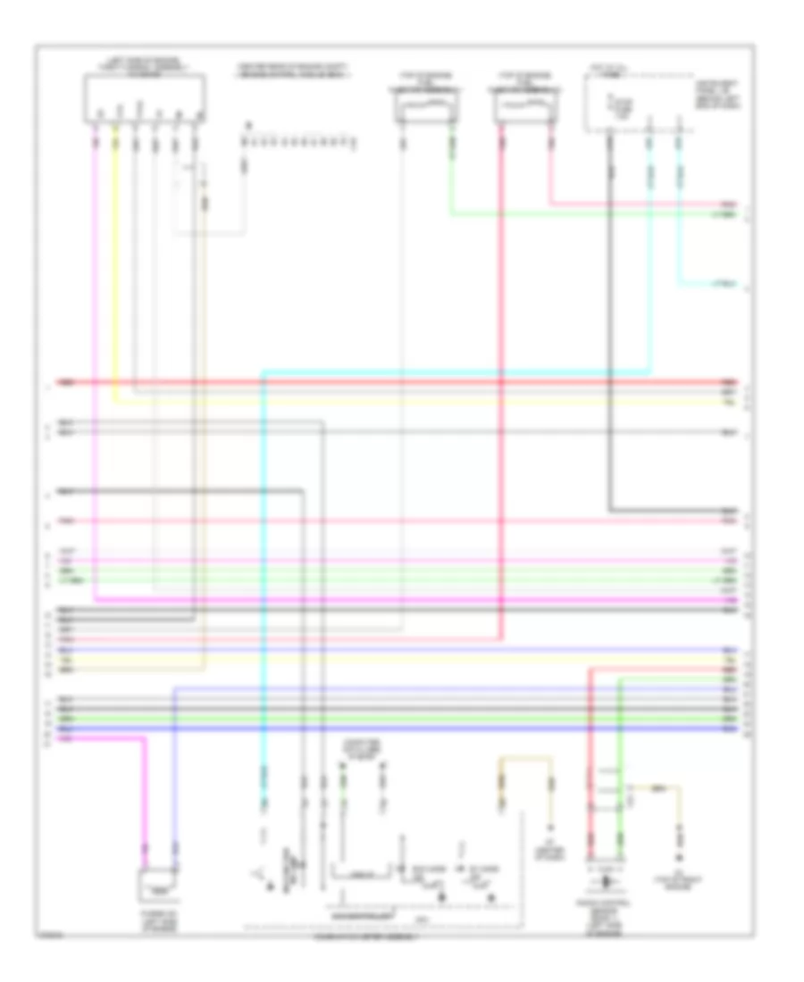
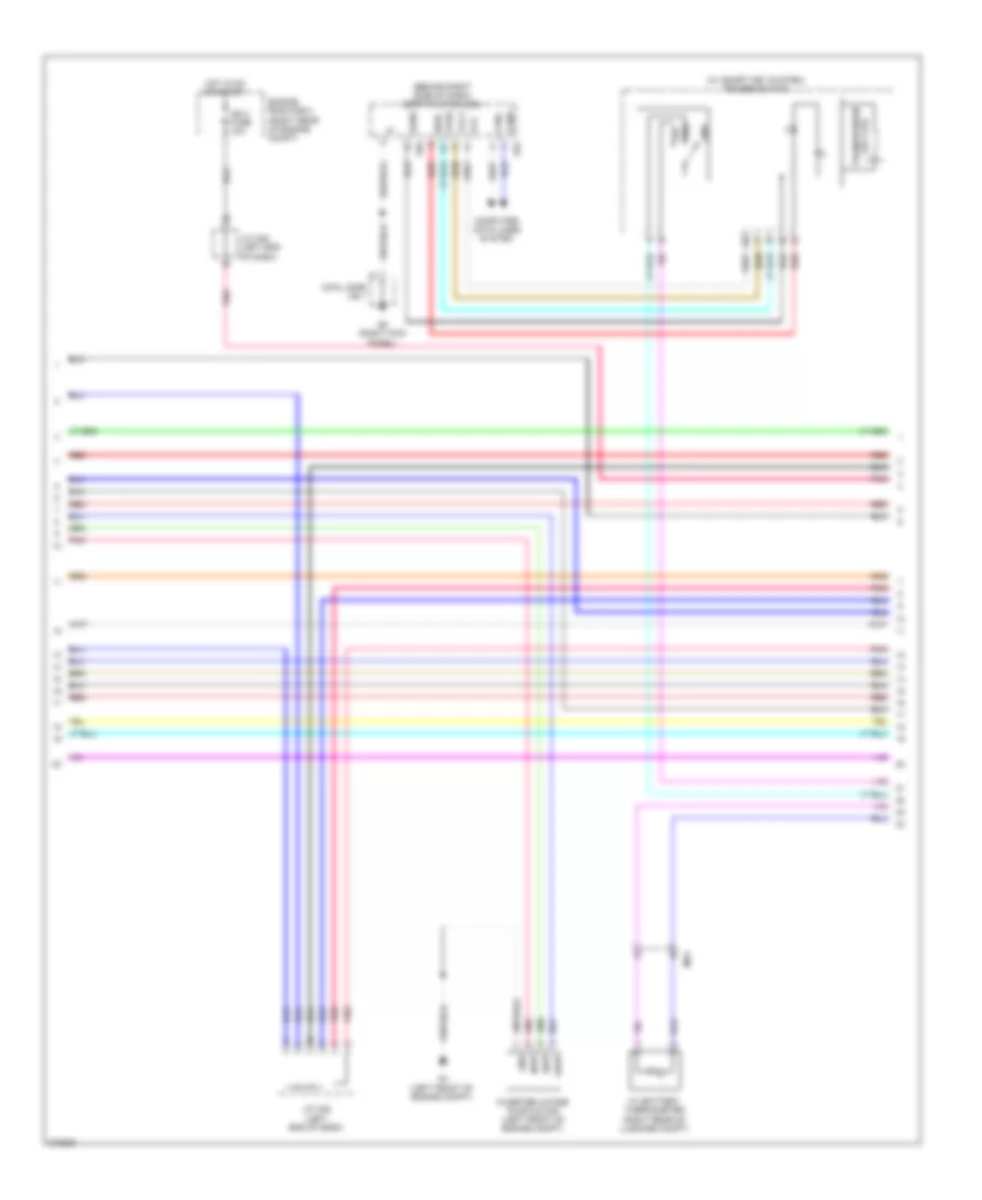
1.5L, Hybrid System Wiring Diagram (2 of 6) for Toyota Prius C 2012
List of elements for 1.5L, Hybrid System Wiring Diagram (2 of 6) for Toyota Prius C 2012:
- (behind right side of dash) certification ecu
- (w/ smart key system) power switch
- +bwp
- A4 (left front of engine compt)
- Agnd
- Canh
- Canl
- Code
- Computer data lines system
- Cowl side j/b 1
- Engine room r/b 2 (right rear of engine compt)
- G5 (right kick panel)
- G54
- G55
- Gnd
- Hot in on or start
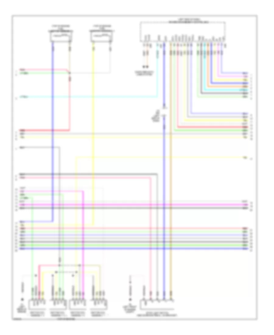
- Hv battery thermometer (right rear of luggage compt)
- Ig2 2 fuse 10a
- Inverter water pump motor (left front of engine compt)
- J/c a48 (left end of dash)
- J/c a49 (left end of dash)
- Mg4
- Nwp
- Pnk
- Red
- Ss1
- Ss2
- Swil
- Swp
- Transponder key coil
- Txct
- Vc5
1.5L, Hybrid System Wiring Diagram (3 of 6) for Toyota Prius C 2012
List of elements for 1.5L, Hybrid System Wiring Diagram (3 of 6) for Toyota Prius C 2012:
- +b2
- A4 (left front of engine compt)
- A47
- Abfs
- Air conditioning system
- Am1
- Am22 batt
- Bth+
- Bth-
- Clk+
- Clk-
- Computer data lines system
- Cowl side j/b 2
- Drn1
- Drn2
- Drn3
- Drn4
- Drn5
- Drn8
- E01
- Ethb
- Evsw
- G4 (left side of dash)
- G57
- G6 (left kick panel)
- G74
- Gnd
- Gnd1
- Gnd2
- Hsdn
- Htm+
- Htm-
- Idh
- Igct
- Ilk
- Ilki
- Ilko
- Inter lock switch (right side of luggage compt)
- Inverter w/ converter (left rear of engine compt)
- J/c g73 & g74 (left side of dash) g73
- Mth+
- Mth-
- Nodd
- Pnk
- Power management control ecu (left end of dash)
- Red
- Req+
- Req-
- Shift lock control ecu
- Smrb
- Smrg
- Smrp
- Spdi
- Ssw1
- Thb
- Vlo
- W/ smart key system
- W/o smart key system
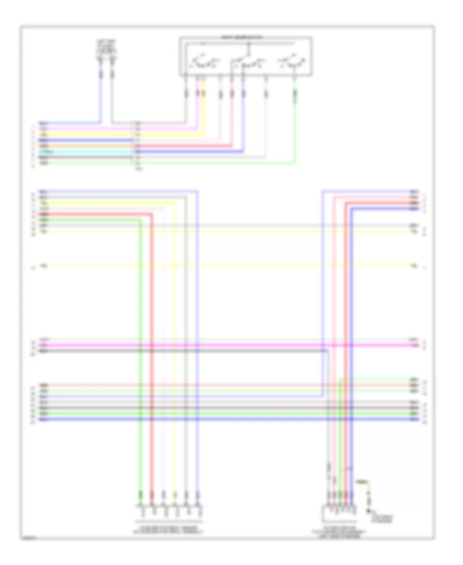
1.5L, Hybrid System Wiring Diagram (4 of 6) for Toyota Prius C 2012
List of elements for 1.5L, Hybrid System Wiring Diagram (4 of 6) for Toyota Prius C 2012:
- (left rear of engine compt) inverter w/ converter
- A4 (left front of engine compt)
- Acc
- Acpb
- Acpe
- Air conditioning system
- Amd
- C24
- C25
- C26
- C28
- Ca1
- Ca2
- Cbi
- Cei
- Cowl side j/b 1
- Dc/dc fuse 100a
- Drn6
- Engine room j/b (left side of engine compt)
- Engine room r/b 2 (right rear of engine compt)
- Ev switch
- G5 (right kick panel)
- Gcs
- Gcsg
- Gmt
- Gmtg
- Gnd
- Grf
- Grfg
- Gsn
- Gsng
- Hot at all times
- Hot in on or start
- Hybrid vehicle transaxle assembly
- Ign fuse 15a
- J/c a50 (left end of dash)
- Mcs
- Mcsg
- Mmt
- Mmtg
- Mrf
- Mrfg
- Msn
- Msng
- Nca
- Out
- Pattern select switch assembly
- Pnk
- Red
- Skid control ecu (left rear of engine compt)
- Stop light switch (above brake pedal, on bracket)
- Stp
- Stp2
- Stpo
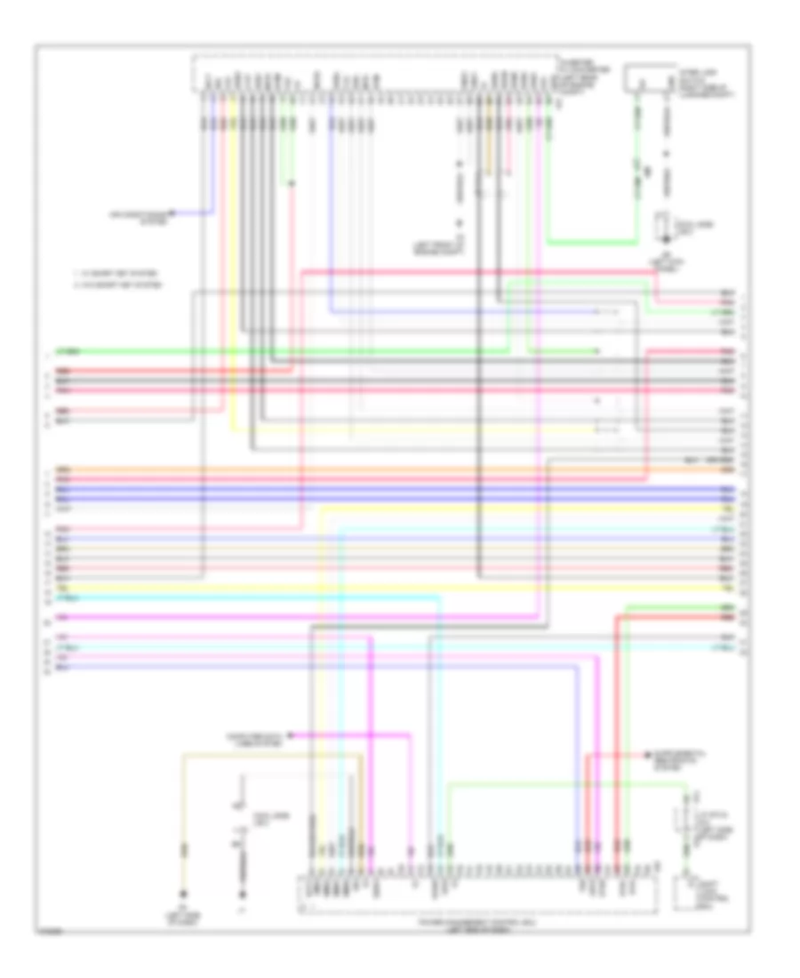
1.5L, Hybrid System Wiring Diagram (5 of 6) for Toyota Prius C 2012
List of elements for 1.5L, Hybrid System Wiring Diagram (5 of 6) for Toyota Prius C 2012:
- (left "c" pillar) j/c m46
- (left end of dash) j/c a49
- (w/o smart key system) ignition or starter switch assembly
- Ag2
- Am1
- Am2
- Battery cooling blower assembly (left end of hybrid battery assembly)
- Battery voltage sensor
- Bth+
- Bth-
- Busbar
- Busbar module
- Cowl side j/b 2
- Current sensor
- Engine room r/b 2 (right rear of engine compt)
- Fp0
- G6 (left kick panel)
- Gb0
- Gb0 z9
- Gb1
- Gb2
- Gc0
- Gib
- Gnd
- Gnd0
- Hot w/ ig2 relay energized
- Hv battery junction block (right side of luggage compt)
- Hybrid junction block assembly (left side of hybrid battery assembly)
- Hybrid vehicle battery
- Ig0
- Ig2
- Ig2 2 fuse 10a
- Igct
- M39
- M40
- Main relay 1
- Main relay 2
- Mg4
- Nca
- Pnk
- Precharge relay
- Red
- Resistor
- Service plug
- Si0
- St2
- Tb0
- Tb1
- Tb2
- Tc0
- Thermistor
- Vb1
- Vb10
- Vb2
- Vb3
- Vb4
- Vb5
- Vb6
- Vb7
- Vb8
- Vb9
- Vib
1.5L, Hybrid System Wiring Diagram (6 of 6) for Toyota Prius C 2012
List of elements for 1.5L, Hybrid System Wiring Diagram (6 of 6) for Toyota Prius C 2012:
- (center rear of engine compt) engine control module (ecm)
- (left rear of engine) c1
- +b1
- A39
- A40
- Accd
- Accelerator pedal sensor (on accelerator pedal assembly)
- Ag2
- Am2 fuse 7.5a
- Am21
- Anti-theft system
- B29
- C10
- C36
- Ca1
- Ca1h
- Ca1l
- Ca3n
- Ca3p
- Canh
- Canl
- Ccs
- Clk+
- Clk-
- Computer data lines system
- Cowl side j/b 2
- Cruise control system
- Db1
- Db2
- Door locks system
- E02
- Ecu-b 2 fuse 7.5a
- Engine room r/b 2 (right rear of engine compt)
- Ep1
- Ep2
- Exterior light system
- G2o
- G58
- G6 (left kick panel)
- Gnd
- Hot at all times
- Hsdn
- Htm+
- Htm-
- Ig1d
- Ig2
- Ig2d
- Igf
- Igf1
- Ignition coil +b assembly (top of engine)
- Ignition coil assembly (top of engine)
- Ignition coil assembly 4 (top of engine)
- Igt1
- Igt2
- Igt3
- Igt4
- Imi
- Imo
- Instrument panel j/b (behind left end of dash)
- Lin2
- Mrel
- Mth+
- Mth-
- N r
- Pnb
- Pnk
- Power distribution system
- Power management control ecu (left end of dash)
- R n
- Red
- Req+
- Req-
- Shift lever position sensor (bottom left side of transaxle)
- Slp
- Slr+
- Ssw2
- St1-
- St2
- Stp
- Vcp1
- Vcp2
- Vpa1
- Vpa2
- W/ smart key system
- W/o smart key system

 Čeština
 Dansk
Dansk Deutsch
 Ελληνικά
 English
 Español
 Suomi
Suomi Français
 Français
 עברית
עברית Hrvatski
 Magyar
 Italiano
 日本語
日本語 한국어
한국어 Nederlands
 Polski
 Português
 Português
 Română
 Русский
 Slovenčina
 Slovenščina
 Svenska
 Türkçe
 中文 (中国)