ENGINE PERFORMANCE
3.0L
3.0L Turbo, Engine Performance Wiring Diagrams (1 of 4) for Toyota Supra 1997
 https://portal-diagnostov.com/license.html
Automotive Electricians Portal FZCO
Automotive Electricians Portal FZCO
https://portal-diagnostov.com/license.html
https://portal-diagnostov.com/license.html
Automotive Electricians Portal FZCO
Automotive Electricians Portal FZCO
List of elements for 3.0L Turbo, Engine Performance Wiring Diagrams (1 of 4) for Toyota Supra 1997:
- (behind center of dash) diode (for idle-up)
- (eng harn, right side of firewall)
- (i/p harn, behind comb meter)
- (i/p harn, right end of dash)
- (i/p harn, right side of dash)
- (left rear of engine) g114
- (splice e11: eng harn, left side of eng block)
- (tachometer)
- A/c
- Abs
- Acc
- Acmg
- Air conditioning system
- Anti-lock brake system
- B10
- B11
- B12
- Batt
- Conn e10
- Conn e9
- Cruise control system
- Data link connector 2 (tdcl) (below dash, left of steering column)
- Data link connector 3 (below dash)
- E11
- E16
- Ect
- Efi+
- Efi-
- Els
- Engine control module (below right front footrest)
- Etc+
- Etc-
- Fpc
- Fuel injector resistor (left side of engine compartment)
- G1-
- G112 (left side of engine)
- Gnd
- Hot at all times
- Hot with defog on
- Hot with light control switch on
- I17
- I20
- Igc1
- Igc2
- Igc3
- Igc4
- Igc5
- Igc6
- Igf
- Ign fuse 7.5a
- Igniter (left side of engine compartment)
- Ignition coils (on top of engine)
- Ignition switch
- Igsw
- Igt1
- Igt2
- Igt3
- Igt4
- Igt5
- Igt6
- Injector 1
- Injector 2
- Injector 3
- Injector 4
- Injector 5
- Injector 6
- Instrument cluster system
- J/b 1 (left kick panel)
- Lock
- M-rel
- Mir-htr fuse 10a
- Nco+
- Nco-
- Ne-
- Neo
- Noise filter (left side of engine compart- ment)
- Od1
- Od2
- Panel fuse 10a
- Pnk
- Red
- Sdl
- Shield
- Sln-
- Slt-
- Slu-
- Sp1
- Sp2+
- Sp2-
- Start
- Stp
- Taco
- Te1
- Vta1
- Vta2
3.0L Turbo, Engine Performance Wiring Diagrams (2 of 4) for Toyota Supra 1997
List of elements for 3.0L Turbo, Engine Performance Wiring Diagrams (2 of 4) for Toyota Supra 1997:
- (eng harn, center of dash)
- (eng harn, left rear of eng block)
- (eng harn, right side of firewall)
- (i/p harn, right end of dash)
- (i/p harn, right side of dash a/t, behind comb meter)
- (i/p harn, right side of dash)
- (right of dash)
- (right side of dash)
- A10
- A11
- A12
- A13
- B10
- B11
- C11
- Combination meter
- Cruise control system
- E12
- E14
- E16
- E17
- Electronic controlled pattern select switch (on center console)
- Electronic controlled transmission solenoid (on transmission)
- G200 (left kick panel)
- G203 (right kick panel)
- Gauge fuse 10a
- H13
- Hot at all times
- Hot in on or start
- I10
- I14
- I14 a/t i8 m/t
- I17
- I18
- I21
- J/b 1 (left kick panel)
- J/c 1 (behind left side of dash)
- Kick down switch (1998) (under left side of dash)
- Man
- Manual ind
- Norm
- O/d direct clutch speed sensor (on transmission)
- O/d main switch (on center console)
- O/d off ind
- Odo & trip
- Park/neutral position switch (on transmission)
- Pnk
- Red
- Right telltale light
- Shield
- Speedometer
- Stop fuse 15a
- Stop light switch (on brake pedal support)
- Vehicle speed sensor 1 (on transmission)
- Vehicle speed sensor 2 (on transmission)
3.0L Turbo, Engine Performance Wiring Diagrams (3 of 4) for Toyota Supra 1997
List of elements for 3.0L Turbo, Engine Performance Wiring Diagrams (3 of 4) for Toyota Supra 1997:
- (eng harn, forward of r/b 2)
- (eng harn, left side of eng block)
- (eng harn, next to r/b 2)
- (eng harn, right side of firewall) e16
- A/t
- A/t only
- Camshaft position sensor 1 (left side of cyl head)
- Camshaft position sensor 2 (left side of cyl head)
- Clutch start switch (m/t only) (above clutch pedal)
- Crankshaft position sensor (lower front of engine)
- Data link connector 1 (check connector) (right side of firewall)
- E12
- E13
- E14
- E16
- E17 a/t (eng harn, center of dash) (eng harn, right side of firewall) e16 m/t
- Efi 2 relay
- Efi main relay
- Efi no.1 fuse 30a
- Efi no.2 fuse 30a
- Fpc
- Fuel pump
- Fuel pump ecu (left rear of vehicle)
- Fuel pump/ fuel sender assembly
- G100 (front side of left fender)
- G114 (left rear of engine)
- G402 (left rear wheel well)
- Hot at all times
- Hot in start
- J/b 1 (left kick panel)
- J/c 2 (behind right side of dash)
- Knock sensor (on front side) (left side of engine)
- Knock sensor (on rear side) (left side of engine)
- Left telltale light
- M/t
- M/t only
- Malfunction ind
- P/n
- Park/neutral position switch (a/t only) (on transmission)
- R/b 2 (left side of engine compartment)
- Red
- Shield
- St fuse 7.5a
- Starting/charging system (starter relay)
- Te1
3.0L Turbo, Engine Performance Wiring Diagrams (4 of 4) for Toyota Supra 1997
List of elements for 3.0L Turbo, Engine Performance Wiring Diagrams (4 of 4) for Toyota Supra 1997:
- (eng harn, left rear of eng block)
- (eng harn, left side of eng block)
- (eng harn, next to r/b 2)
- (eng harn, upper front of eng block)
- (eng harn, upper front of engine block)
- (left rear of engine)
- (left side of engine) turbo pressure sensor
- (left side of engine)
- (on throttle body)
- (on transmission) a/t fluid temp sensor
- (right
- (right front
- (right front of engine) mass air flow meter
- (right rear
- (right side of firewall)
- (under left
- (under throttle body) sub throttle position sensor
- Anti-lock brakes system
- Conn e9
- E01
- E02
- E10
- E11
- E12
- E13
- E14
- E16
- E21
- Efif
- Egr
- Egr gas temp sensor
- Egr vsv (left side of engine)
- Engine control module (below right front footrest)
- Engine coolant temperature sensor (front of engine)
- Evap
- Evap vsv (left side of engine)
- Exhaust bypass
- Exhaust control
- Fail
- Fpu
- Fuel pressure up vsv (left side of engine)
- G114 (left rear of engine)
- Ht1
- Ht2
- I17
- Idl1
- Idl2
- Idle air control valve (left side of engine)
- Igf
- Igt1
- Igt2
- Igt3
- Igt4
- Igt5
- Igt6
- Intake air control
- Isc1
- Isc2
- Isc3
- Isc4
- Knk1
- Knk2
- Main heated oxygen sensor side of engine)
- Nsw
- Of engine)
- Oil
- Ox1
- Ox2
- Pim
- Pm1
- Pmc
- Pnk
- Red
- Sensor
- Shield
- Side of vehicle)
- Slt+
- Sta
- Sub heated oxygen
- Tha
- Thg
- Throttle position sensor
- Thw
- Vcc
- Vsv
- Vsv1
- Vsv2
- Vsv3
- Vta1
- Vta2
- Waste gate vsv (right front of engine)
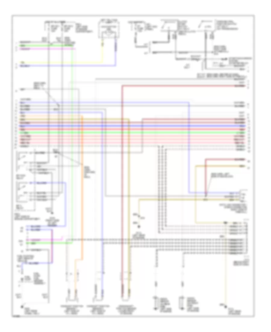
3.0L, Engine Performance Wiring Diagrams (1 of 4) for Toyota Supra 1997
List of elements for 3.0L, Engine Performance Wiring Diagrams (1 of 4) for Toyota Supra 1997:
- #10
- #20
- #30
- #40
- #50
- #60
- (eng harn, right side of fire- wall)
- (eng harn, right side of firewall)
- (engine harness, right side of firewall)
- (i/p harn, left kick panel)
- (i/p harn, right end of dash)
- (left rear of engine) g114
- (rear side of intake manifold) g112
- A/c
- Acc
- Acmg
- Air conditioning system
- Bat
- Batt
- C14
- Conn e10
- Conn e9
- Crankshaft position sensor (front of engine)
- Cruise control system
- Data link connector 3 (left side of i/p)
- Diode (dle-up) (behind left side of i/p)
- Distributor (right front of engine)
- E22 (eng harn, upper right front of eng block)
- E28
- Els
- Engine control module (below left side of i/p)
- Ext
- Fpc
- G112 (left side of engine)
- G131 (front side of intake manifold)
- G200 (left kick panel)
- Hot at all times
- Hot with defog on
- Hot with light control switch on
- Ht3
- I20
- Igf
- Ign fuse 7.5a
- Igniter (left side of engine compartment)
- Ignition coil (right side of engine compartment)
- Ignition switch
- Igsw
- Igt
- Injector no.1
- Injector no.2
- Injector no.3
- Injector no.4
- Injector no.5
- Injector no.6
- J/b no.1 (left kick panel)
- Lock
- M-rel
- Mir-htr fuse 10a
- Nca
- Ne2+
- Ne2-
- Noise filter (right side of engine compartment)
- Obd 2 fuse 7.5a
- Od1
- Od2
- Ox3
- Panel fuse 10a
- Pnk
- Power steering pressure switch (left front of engine compt)
- Power steering pressure switch (right side of engine compt)
- Red
- Sdl
- Shield
- Sp1
- Sp2+
- Sp2-
- Start
- Stp
- Te1
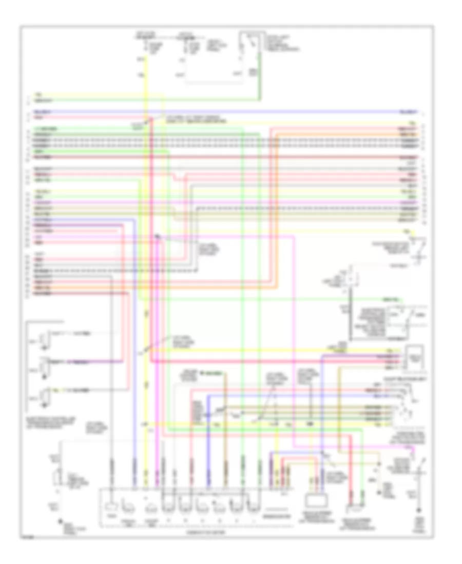
3.0L, Engine Performance Wiring Diagrams (2 of 4) for Toyota Supra 1997
List of elements for 3.0L, Engine Performance Wiring Diagrams (2 of 4) for Toyota Supra 1997:
- (eng harn, right side of fire- wall)
- (i/p harn, a/t: right side of dash, m/t: behind comb meter)
- (i/p harn, right end of dash)
- (i/p harn, right side of dash)
- (i/p harn, right side of fire- wall)
- A10
- A11
- A12
- A13
- B10
- B11
- C11
- C13
- Combination meter
- Cruise control system
- E12
- E28
- Electronic controlled transmission pattern select switch (on center console)
- Electronic controlled transmission solenoid (on transmission)
- G200 (left kick panel)
- G203 (right kick panel)
- Gauge fuse 10a
- H13
- Hot at all times
- Hot in on or start
- I10
- I14
- I14 a/t i8 m/t
- I17
- I21
- J/b 1 (left kick panel)
- J/b no.1 (left kick panel)
- J/c 1 (behind left side of i/p)
- Kick down switch (behind left side of i/p)
- Man
- Manual ind
- No.1
- No.2
- No.3
- Norm
- O/d main switch (on center console)
- O/d off ind
- Odo & trip
- Park/neutral position switch (on transmission)
- Pnk
- Red
- Right telltale light
- Shield
- Speedometer
- Stop fuse 15a
- Stop light switch (on brake pedal support)
- Tach
- Vehicle speed sensor no.1 (on transmission)
- Vehicle speed sensor no.2 (on transmission)
3.0L, Engine Performance Wiring Diagrams (3 of 4) for Toyota Supra 1997
List of elements for 3.0L, Engine Performance Wiring Diagrams (3 of 4) for Toyota Supra 1997:
- (eng harn, forward of r/b 2)
- (eng harn, left rear of eng block)
- (eng harn, left rear of engine)
- (eng harn, right side of firewall)
- (eng harn, upper front of eng block) e23
- (eng harn, upper front of engine block)
- (front side of left fender) g100
- (i/p harn, left end of dash)
- (i/p harn, right side of dash)
- A/t
- A/t only
- Clutch start switch (a/t) (under left side of i/p)
- Data link connector #1 (check connector) (right rear of engine compartment)
- E20
- E23
- E23 (eng harn, upper front of engine block)
- E26
- E27 (eng harn, left rear of eng block)
- E28
- Efi main relay (in r/b no.2) (left side of engine compartment)
- Efi no.1 fuse 30a
- Fpc
- Fuel pump
- Fuel pump ecu (left rear of vehicle)
- G112 (rear side of intake manifold)
- G904 (left quarter pillar)
- Hot at all times
- Hot in start
- I17
- Instrument cluster system (combination meter)
- J/b no.1 (left kick panel)
- J/c 2 (behind right side of i/p)
- Knock sensor (on front side) (left front engine)
- Knock sensor (on rear side) (left rear side of engine)
- Left telltale light
- M/t
- M/t only
- Main heated oxygen sensor (calif. models) (on front side) (right front of engine)
- Main heated oxygen sensor (calif. models) (on rear side) (left side of engine)
- Malfunction ind
- Nca
- P/n
- Park/neutral position switch (a/t) (on transmission)
- R/b no.2 (left side of engine compartment)
- Red
- Shield
- St fuse 7.5a
- Starting/charging system (starter relay)
- Te1
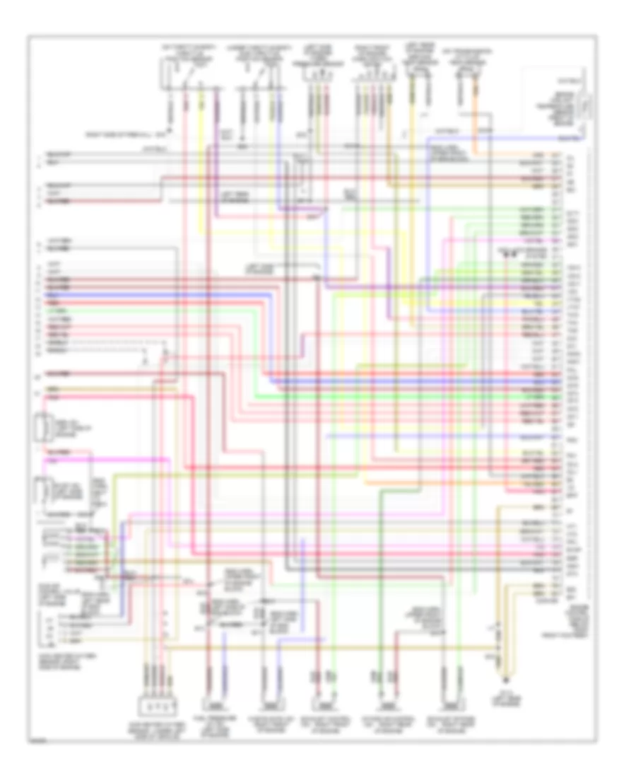
3.0L, Engine Performance Wiring Diagrams (4 of 4) for Toyota Supra 1997
List of elements for 3.0L, Engine Performance Wiring Diagrams (4 of 4) for Toyota Supra 1997:
- (a/t)
- (eng harn, left rear of eng block)
- (eng harn, left rear of eng block) e26
- (eng harn, left rear of eng)
- (eng harn, left side of eng block)
- (eng harn, right side of safety wall)
- (i/p harn, right side of dash)
- A/t fluid temp sensor (on transmission)
- Acis vsv (left rear of engine)
- Conn e9
- Cruise control system
- E01
- E02
- E03
- E24
- E26
- E28
- E2g
- Egr
- Egr gas temp sensor (left rear of engine)
- Egr vsv (left side of engine)
- Engine control module (below right side of i/p)
- Engine coolant temp sensor (left front of engine)
- Evap
- Evap vsv (left rear of eng)
- Fpu
- Fuel pressure up vsv (left side of eng)
- G112 (rear side of intake manifold)
- Ht1
- Ht2
- I17
- Idl1
- Idle air control valve (right side of engine)
- Igf
- Igt
- Isc1
- Isc2
- Isc3
- Isc4
- Knk1
- Knk2
- Mass air flow meter (right side of engine compt)
- Nsw
- Ox1
- Ox2
- Pnk
- Red
- Shield
- Sta
- Sub heated oxygen sensor (calif. models) (under left side of vehicle)
- Tha
- Thg
- Tho
- Throttle position sensor (left side of engine)
- Thw
- Vcc
- Vsv2
- Vta1

 Čeština
 Dansk
Dansk Deutsch
 Ελληνικά
 English
 English
 Español
 Suomi
Suomi Français
 Français
 עברית
עברית Hrvatski
 Magyar
 Italiano
 日本語
日本語 한국어
한국어 Nederlands
 Português
 Português
 Română
 Русский
 Slovenčina
 Slovenščina
 Svenska
 Türkçe
 中文 (中国)