ENGINE PERFORMANCE
2.7L
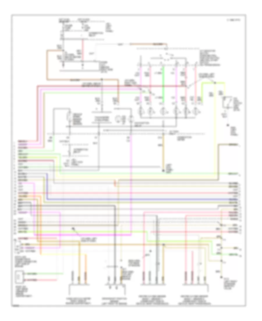
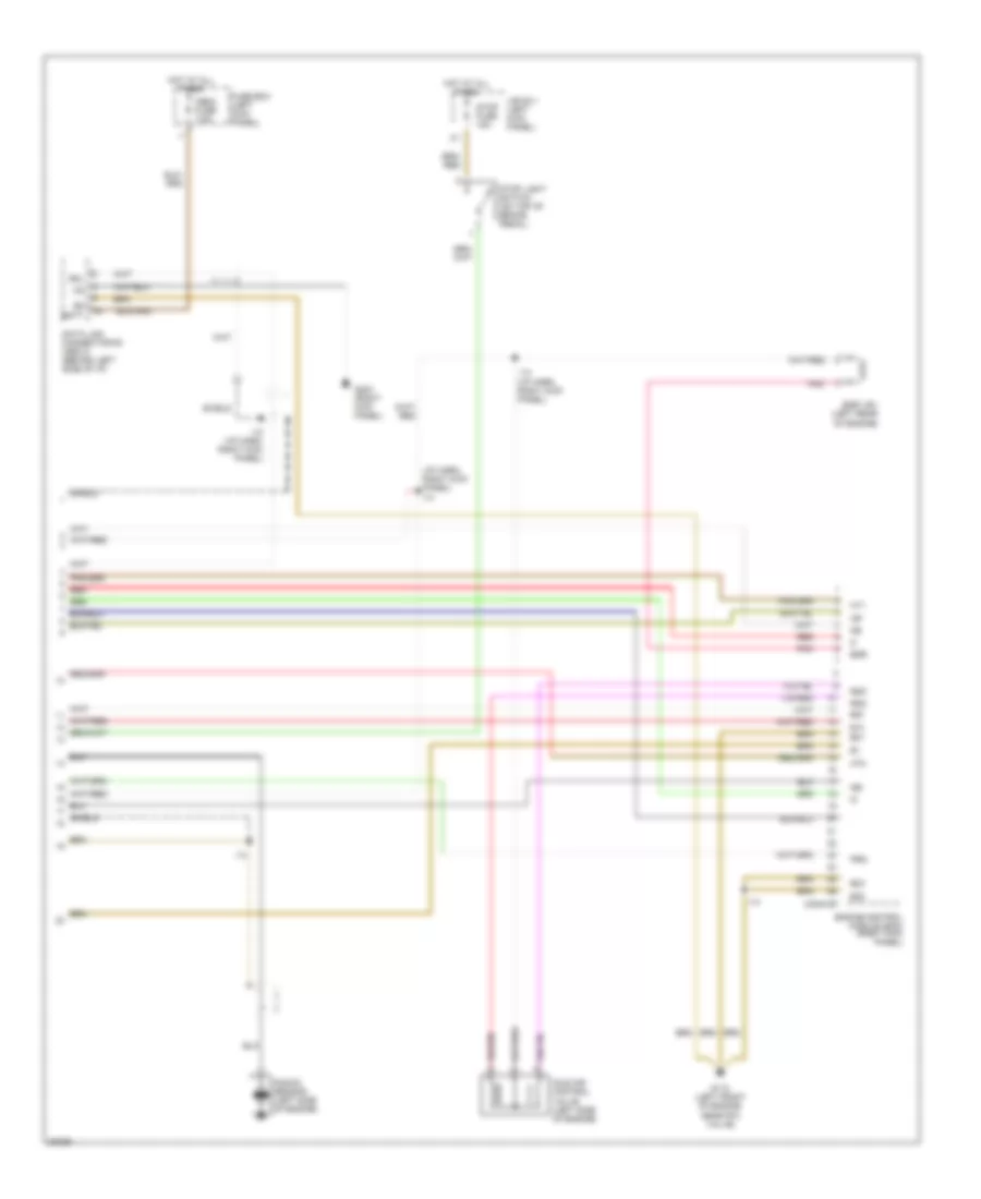
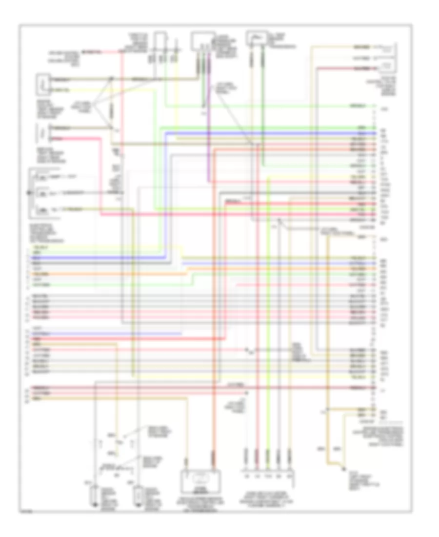
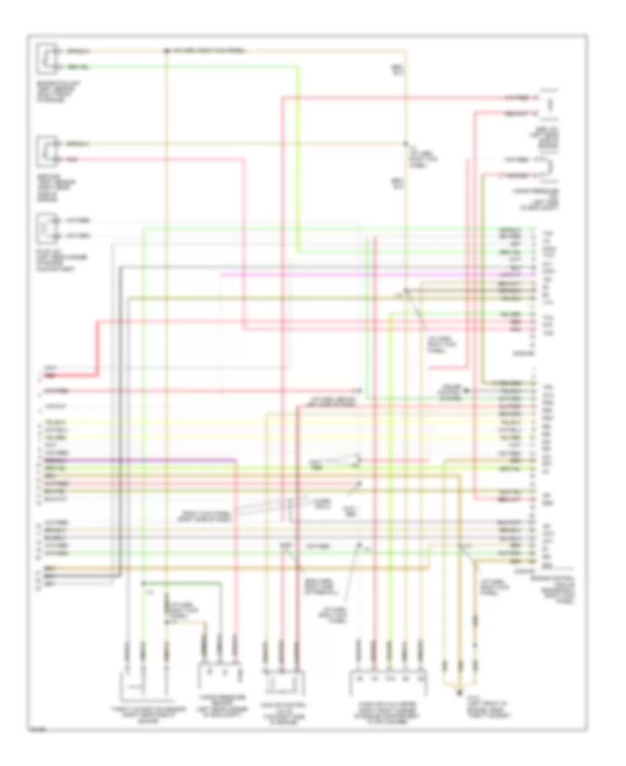
2.7L, Engine Performance Wiring Diagrams, A/T (1 of 3) for Toyota T100 SR5 1997
 https://portal-diagnostov.com/license.html
Automotive Electricians Portal FZCO
Automotive Electricians Portal FZCO
https://portal-diagnostov.com/license.html
https://portal-diagnostov.com/license.html
Automotive Electricians Portal FZCO
Automotive Electricians Portal FZCO
List of elements for 2.7L, Engine Performance Wiring Diagrams, A/T (1 of 3) for Toyota T100 SR5 1997:
- (eng harn, top rear of engine)
- (i/p harn, above center of dash)
- (i/p harn, left side of dash)
- (i/p harn, left side of dash) i1
- (i/p harn, right kick panel)
- (i/p harn, right kick panel) i14
- (i/p harn, right side of dash)
- (left kick panel) g200
- (right kick panel)
- (right side of engine compartment)
- 1995 vftc c
- A/c amplifier (behind right side of i/p)
- Acc
- Aci
- Act
- Am1 fuse 40a
- Batt
- C13
- C17
- Circuit opening relay (behind right side of i/p)
- Conn e4
- Conn e5
- Conn e6
- Cruise control system
- Distributor (right front side of g+
- E16
- Efi fuse 15a
- Efi main relay
- Egr gas temp. sensor (top left rear of engine)
- Engine & electronic controlled transmission electronic control module (ecm)
- Engine coolant temp. sensor (right rear of engine)
- Engine)
- Fuel injectors (on top of engine)
- Fuel pump (under center of vehicle)
- G100 (left front fender)
- G200 (left kick panel)
- G203 (right
- Hot at all times
- I12 (i/p harn, right kick panel)
- I14
- I16
- Idl
- Ig2
- Ign fuse 7.5a
- Igniter
- Ignition switch
- Intake air temp. sensor (right front of engine compartment)
- J/b 1 (left kick panel)
- Kick panel)
- Knk
- Lock
- Ne-
- Noise filter (for ign, system) (right side of engine compt.)
- Nsw
- Od1
- Od2
- Ox1
- Ox2
- P/n
- Park/neutral position switch (on transmission)
- Prg
- R/b no.2 (left side of engine compartment)
- Red
- Sdl
- Sp1
- Sp2+
- Sp2-
- St1
- Sta
- Start
- Starter relay (left kick panel)
- Starting system (starter motor)
- Te1
- Tha
- Thg
- Throttle position sensor (top left side of engine)
- Thw
- Vcc
- Vta
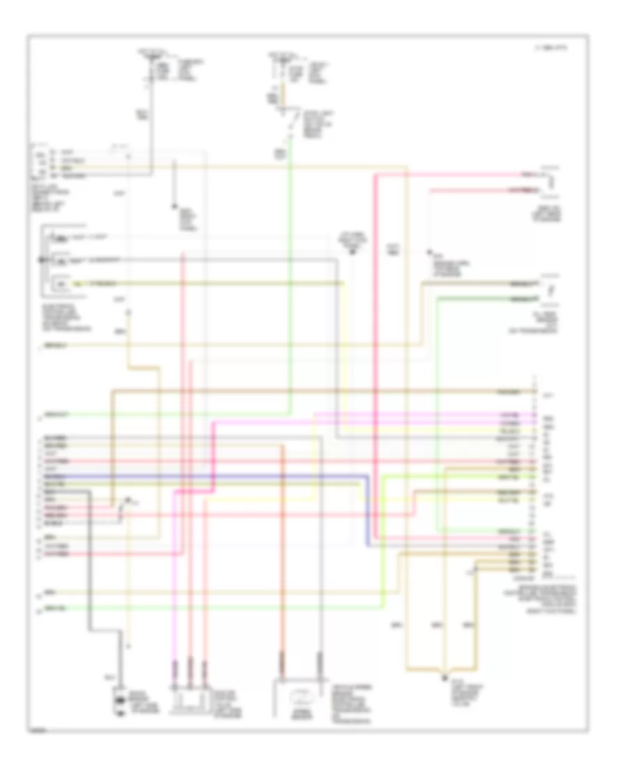
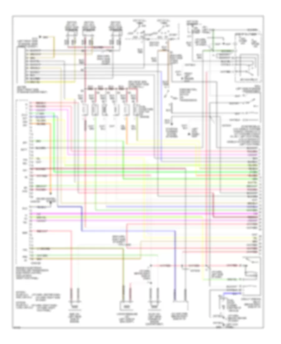
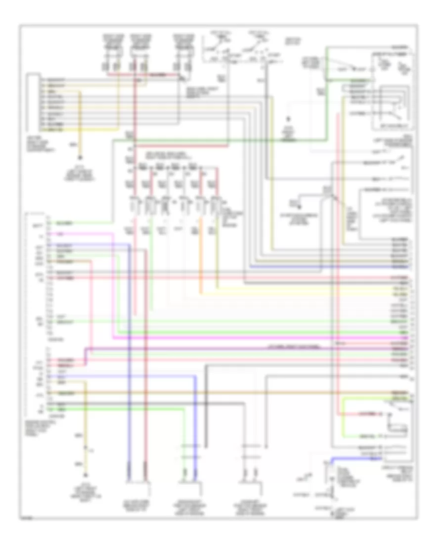
2.7L, Engine Performance Wiring Diagrams, A/T (2 of 3) for Toyota T100 SR5 1997
List of elements for 2.7L, Engine Performance Wiring Diagrams, A/T (2 of 3) for Toyota T100 SR5 1997:
- (eng harn, top left rear of engine)
- (eng harn, top rear of engine)
- (i/p harn, above center of dash)
- (i/p harn, left side of dash)
- (i/p harn, right kick panel)
- (left kick panel) g200
- 1995 vftc c
- A/t indicator switch (park/neutral position switch) (neutral start switch) (on transmission)
- Cig fuse 15a
- Combination meter
- Crankshaft position sensor (left front of engine)
- D12
- Data link connector #1 (check connector) (left side of engine)
- Diode (a/t) (behind right side of i/p)
- E16
- E17
- Evap vsv (left rear corner of engine compartment)
- G110 (left front of engine, near fpu valve)
- G200 (left kick panel)
- Gauge fuse 10a
- Heated oxygen sensor (bank 1, sensor 1) (under right side of vehicle, near transmission)
- Heated oxygen sensor (bank 1, sensor 2) (under right side of vehicle, near transmission)
- Hot in acc or on
- Hot in on or start
- I12
- I14
- I6 (i/p harn, above center of dash)
- Integration relay
- J/b 1 (left kick panel)
- Malfunction ind lp
- Mass air flow meter (right side of engine compartment)
- Ne-
- O/d main switch (left side of i/p)
- O/d off ind lp
- Shield
- Tachometer (if equipped)
- Te1
- Vehicle speed sensor (speed sensor)
- W/ tach. only
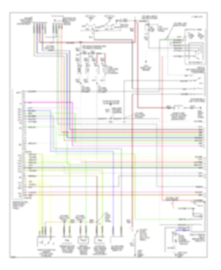
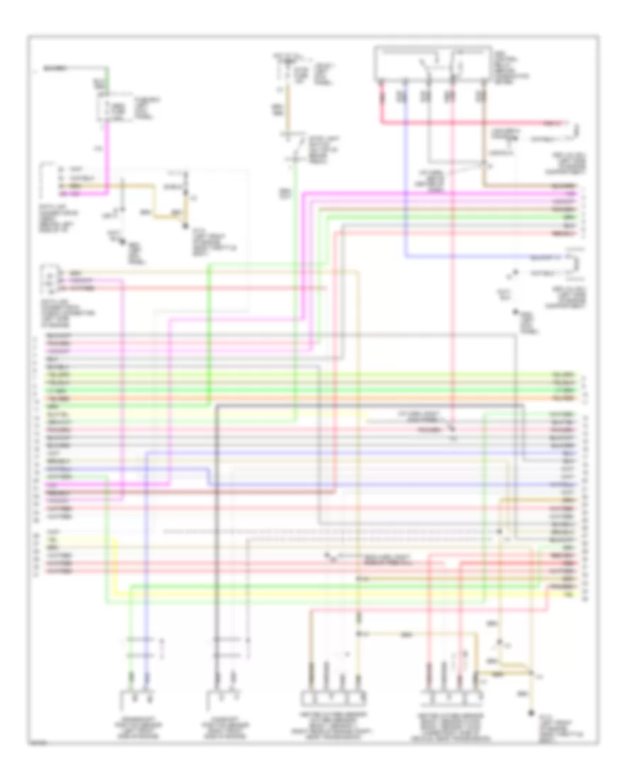
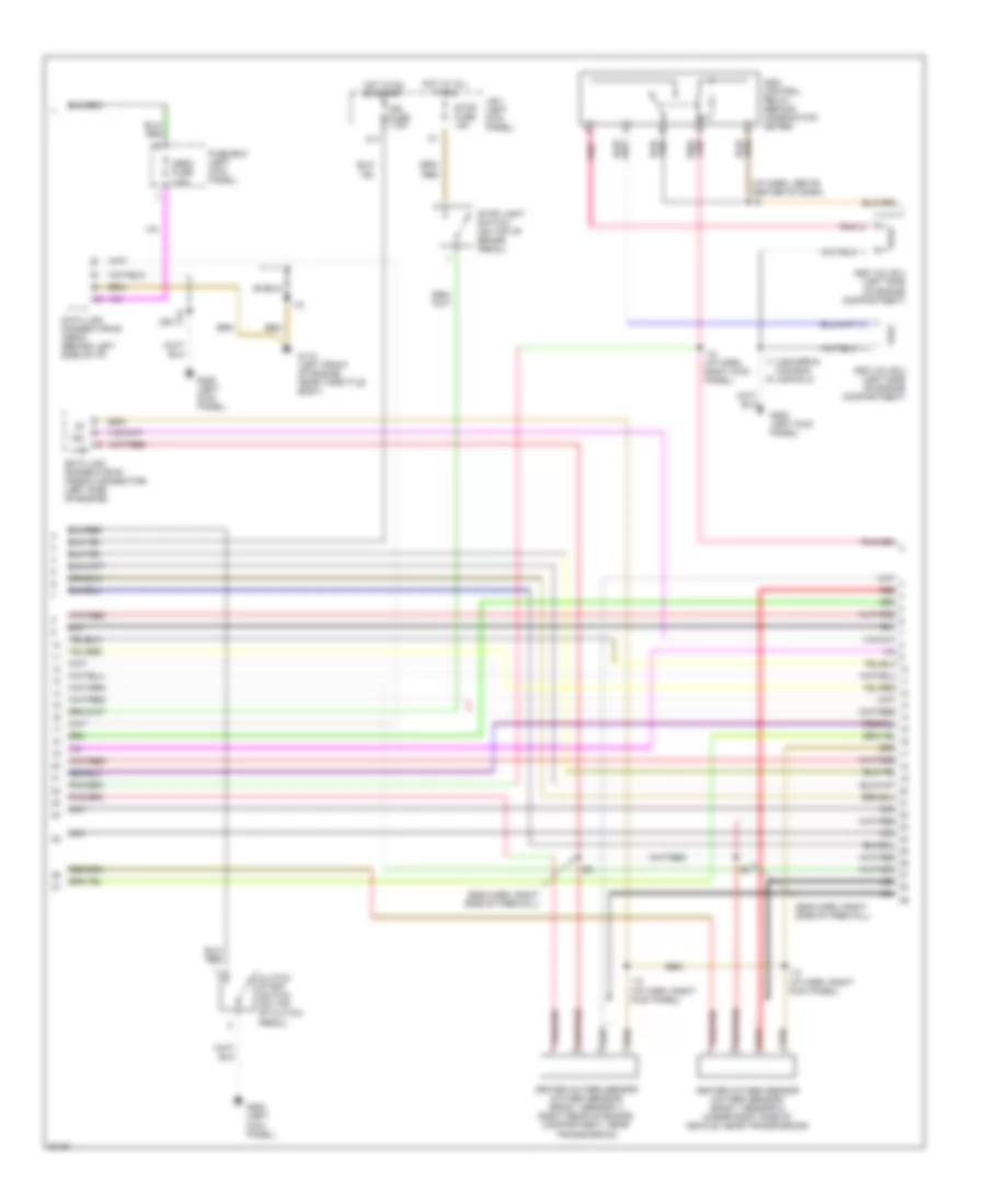
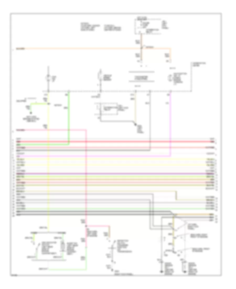
2.7L, Engine Performance Wiring Diagrams, A/T (3 of 3) for Toyota T100 SR5 1997
List of elements for 2.7L, Engine Performance Wiring Diagrams, A/T (3 of 3) for Toyota T100 SR5 1997:
- #10
- #20
- (engine harn, top rear of engine)
- (i/p harn, right kick panel) i14
- (left side of engine)
- (right kick panel)
- 1995 vftc c
- Batt
- Conn e7
- Data link connector #3 (obd 2) (behind left side of i/p)
- E01
- E02
- E03
- E16
- Egr
- Egr vsv (left rear of engine)
- Electronic controlled transmission solenoid (on transmission)
- Engine & electronic controlled transmission electronic control module (ecm)
- Fuse box (left kick panel)
- G110 (left front of engine, near fpu valve)
- G203 (right kick panel)
- Hot at all times
- Ht1
- Ht2
- I14
- Idle air control valve (left side of engine)
- Igf
- Igt1
- J/b no.1 (left kick panel)
- Knock
- Obd2 fuse 7.5a
- Oil
- Oil temp. sensor (a/t) (on transmission)
- Pnk
- Rsc
- Rso
- Sdl
- Sensor
- Speed sensor
- Stop fuse 15a
- Stop light switch (on top of brake pedal)
- Vehicle speed sensor (electronic controlled transmission) (on transmission)
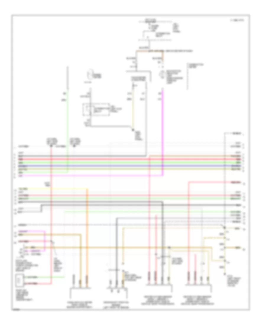
2.7L, Engine Performance Wiring Diagrams, M/T (1 of 3) for Toyota T100 SR5 1997
List of elements for 2.7L, Engine Performance Wiring Diagrams, M/T (1 of 3) for Toyota T100 SR5 1997:
- (eng harn, top rear of engine)
- (i/p harn, above center of dash)
- (i/p harn, left side of dash)
- (i/p harn, right kick panel)
- (i/p harn, right kick panel) i14
- (i/p harn, right side of dash)
- (left kick panel) g200
- (left kick panel) g200
- (right side of engine compartment)
- (splice e16: engine harn, top rear of engine)
- 1995 vftc c
- A/c amplifier (behind right side of i/p)
- Ac1
- Acc
- Act
- Am1 fuse 40a
- Batt
- C17
- Circuit opening relay (behind right side of i/p)
- Clutch start switch (on top of clutch pedal)
- Conn e4
- Conn e6
- Distributor (right front side of g+
- E16
- Efi fuse 15a
- Efi main relay
- Egr gas temp. sensor (top left rear of engine)
- Engine control module (ecm) (right kick panel)
- Engine coolant temp. sensor (right rear of engine)
- Engine)
- Fuel injectors (on top of engine)
- Fuel pump (under center of vehicle)
- G100 (front left fender)
- G203 (right kick panel)
- Hot at all times
- I14
- I14 (i/p harn, left side of dash)
- Idl
- Ig2
- Ign fuse 7.5a
- Igniter
- Ignition switch
- Intake air temp. sensor (right front of engine compartment)
- J/b 1 (left kick panel)
- Knk
- Lock
- Noise filter (for ign. system) (right side of engine compt.)
- Ox1
- Ox2
- R/b no.2 (left side of engine compartment)
- Red
- Sdl
- Shield
- Sp1
- St1
- Sta
- Start
- Starter relay (left kick panel)
- Starting system (starter motor)
- Te1
- Tha
- Thg
- Throttle position sensor (top left side of engine)
- Thw
- Vcc
- Vta
2.7L, Engine Performance Wiring Diagrams, M/T (2 of 3) for Toyota T100 SR5 1997
List of elements for 2.7L, Engine Performance Wiring Diagrams, M/T (2 of 3) for Toyota T100 SR5 1997:
- (eng harn, top left rear of engine)
- (i/p harn, above center of dash)
- (i/p harn, behind left side of dash)
- (i/p harn, left side of dash)
- (i/p harn, left side of dash) i14
- 1995 vftc c
- Combination meter
- Crankshaft position sensor (left front of engine)
- D12
- Data link connector #1 (check connector) (left side of engine)
- E17
- Evap vsv (left rear corner of engine compartment)
- G110 (left front of engine, near fpu valve)
- G200 (left kick panel)
- Gauge fuse 10a
- Heated oxygen sensor (bank 1, sensor 1) (under right side of vehicle, near transmission)
- Heated oxygen sensor (bank 1, sensor 2) (under right side of vehicle, near transmission)
- Hot in on or start
- I14
- Integration relay
- J/b 1 (left kick panel)
- Malfunction indicator lamp (check engine warning lamp)
- Mass air flow meter (right side of engine compartment)
- Ne-
- Red
- Shield
- Speed meter
- Tachometer (if equipped)
- Te1
2.7L, Engine Performance Wiring Diagrams, M/T (3 of 3) for Toyota T100 SR5 1997
List of elements for 2.7L, Engine Performance Wiring Diagrams, M/T (3 of 3) for Toyota T100 SR5 1997:
- #10
- #20
- (i/p harn, right kick panel)
- (i/p harn, right kick panel) i14
- Batt
- Conn e7
- Data link connector #3 (obd 2) (behind left side of i/p)
- E01
- E02
- E03
- Egr
- Egr vsv (left rear of engine)
- Engine control module (ecm) (right kick panel)
- Fuse box (left kick panel)
- G110 (left front of engine, near fpu valve)
- G203 (right kick panel)
- Hot at all times
- Ht1
- Ht2
- I12 (i/p harn, right kick panel)
- I14
- Idle air control valve (left side of engine)
- Igf
- J/b no.1 (left kick panel)
- Knock sensor (left side of engine)
- Ne-
- Obd2 fuse 7.5a
- Pnk
- Prg
- Red
- Rsc
- Rso
- Sdl
- Shield
- Stop fuse 15a
- Stop light switch (on top of brake pedal)
3.4L
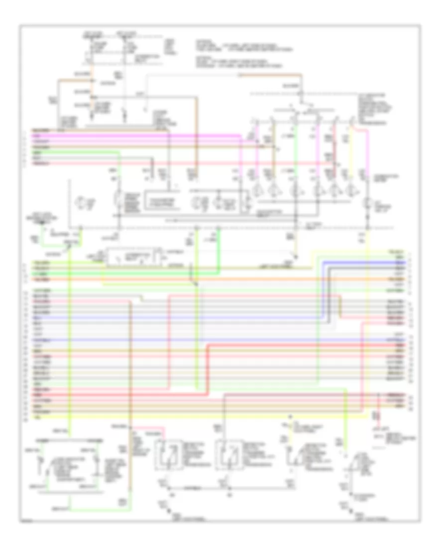
3.4L, Engine Performance Wiring Diagrams, A/T (1 of 4) for Toyota T100 SR5 1997
List of elements for 3.4L, Engine Performance Wiring Diagrams, A/T (1 of 4) for Toyota T100 SR5 1997:
- (eng harn, right side of eng compt)
- (eng harn, right side of safety wall) e3
- (front left fender) g100
- (i/p harn, behind center of dash)
- (i/p harn, behind right side of dash)
- (i/p harn, center dash)
- (i/p harn, left side of dash)
- (i/p harn, right dash)
- (i/p harn, right kick panel)
- (i/p harn, right side of dash)
- (left kick panel)
- (left kick panel) g200
- (on transmission)
- (splice e3: eng harn, right side of firewall)
- 4wd
- A/c amplifier (behind right side of i/p)
- Ac1
- Acc
- Act
- Am1
- Am1 fuse 40a
- Am2
- Batt
- C17
- Circuit opening relay (behind right side of i/p)
- Conn e4
- Conn e5
- Cruise control system
- Efi fuse 15a
- Efi main relay
- Egr
- Egr vsv (left rear side of engine)
- Engine & electronic controlled transmission electronic control module (ecm) (right kick panel)
- Evap vsv (left rear corner of engine compartment)
- Fuel injectors (on top of engine)
- Fuel pump (under center of vehicle)
- G110 (left front side of engine, near throttle body)
- G200
- Hot at all times
- Hot in on or start
- Idlo
- Ig2
- Ign fuse 7.5a
- Igniter (right front side of engine compartment)
- Ignition coil no.1 (right side of engine)
- Ignition coil no.2 (right side of engine)
- Ignition coil no.3 (right side of engine)
- Ignition switch
- J/b 1 (left kick panel)
- Lock
- Note #1
- Note #1: i6-usa dlx i9-ex usa dlx
- Note #2
- Note #2: i9-usa dlx i12-ex usa dlx
- Od1
- Od2
- Oilw
- P&n
- Park/neutral position switch
- Prg
- R/b 2 (left side of engine compartment)
- Red
- Sdl
- Sp1
- St1
- Start
- Starter relay (u.s. models: w/power window, canada a/t & m/t w/power window (in j/b 1: left kick panel) (u.s. & canada m/t models w/o power window (left kick panel)
- Starting/ charging system (starter)
- Te1
- Tfn
- Tpc
- Vapor pressure vsv (left side of eng compt)
3.4L, Engine Performance Wiring Diagrams, A/T (2 of 4) for Toyota T100 SR5 1997
List of elements for 3.4L, Engine Performance Wiring Diagrams, A/T (2 of 4) for Toyota T100 SR5 1997:
- (eng harn, right side of firewall)
- (i/p harn, above center of dash)
- (i/p harn, right kick panel)
- (usa-dlx)
- (usa-sr5 & canada)
- Add control relay (behind combination meter)
- Add valve 2 (left side of engine compartment)
- Add valve 4 (left side of engine compartment)
- Camshaft position sensor (right front side of engine)
- Crankshaft position sensor (left front side of engine)
- Data link connector #1 (check connector) (left side of engine)
- Data link connector #3 (obd2) (behind left side of i/p)
- Fuse box (left kick panel)
- G110 (left front of engine, near throttle body)
- G200 (left kick panel)
- Heated oxygen sensor (bank 1 sensor 2-4wd) (bank 1 sensor 1-2wd) (under right side of vehicle, near transmission)
- Heated oxygen sensor (oxygen sensor) (bank 1 sensor 1) (right rear of engine compt., near transmission)
- Hot at all times
- Ht1
- Ht2
- I12
- I14
- I6 (or i7)
- I6 i1
- J/b no.1 (left kick panel)
- Ne-
- Obd2 fuse 7.5a
- Ox1
- Ox2
- Pnk
- Red
- Shield
- Stop fuse 15a
- Stop light switch (on top of brake pedal)
- Te1
3.4L, Engine Performance Wiring Diagrams, A/T (3 of 4) for Toyota T100 SR5 1997
List of elements for 3.4L, Engine Performance Wiring Diagrams, A/T (3 of 4) for Toyota T100 SR5 1997:
- (eng harn, left front of engine)
- (i/p harn, above center of dash)
- (i/p harn, behind center of dash)
- (i/p harn, center of dash) i6
- (i/p harn, left side of dash)
- (i/p harn, right side of dash)
- (left kick panel)
- 4wd
- 4wd ind. lp
- A/t indicator switch (park/neutral position switch) (neutral start switch) (on transmission)
- A/t oil temp. ind lp
- A/t parking ind. lp
- A10
- A12
- A15
- Abs ecu (below center of dash)
- Add indicator switch (left rear side of engine compartment)
- Anti-lock brakes system (abs ecu)
- Center of dash)
- Cig fuse 15a
- Combination meter
- Detection switch (transfer l4 position, a/t) (on transmission)
- Detection switch (transfer neutral position, a/t) (on transmission)
- Detection switch (transfer position) (on transmission)
- Diode (a/t) (behind right side of i/p)
- Ex13
- G200 (left kick panel)
- G20o
- Gauge fuse 10a
- Hot in acc or on
- Hot in on or start
- I12
- I12 (i/p harn, right kick panel)
- I6 (canada) i7 (usa)
- If equipped
- Integration relay
- J/b #1 (left kick panel)
- J/b 1 (left kick panel)
- Malfunction ind lp.
- Note #3
- Note #3: i5-usa sr5 i7-ex usa sr5
- Note #4
- Note #4: i9-usa i6-canada
- O/d main switch (left side of i/p)
- O/d off ind lp
- Red
- Short pin (left rear side of engine compart- ment)
- Tachometer (if equipped)
- Vehicle speed sensor (speed sensor)
- W/ tach. only
- W/add
- W/o add
3.4L, Engine Performance Wiring Diagrams, A/T (4 of 4) for Toyota T100 SR5 1997
List of elements for 3.4L, Engine Performance Wiring Diagrams, A/T (4 of 4) for Toyota T100 SR5 1997:
- #10
- #20
- #30
- #40
- #50
- #60
- (eng harn, front of engine)
- (eng harn, right front of engine)
- (eng harn, right side of firewall)
- (i/p harn, right kick panel)
- (right kick panel)
- Conn e6
- Conn e7
- Cruise control system (cruise control ecu)
- E01
- E02
- Egr gas temp. sensor (right rear side of engine)
- Electronic controlled transmission solenoid (on transmission)
- Engine coolant temp. sensor (right front of engine)
- Engine & electronic controlled transmission electronic control module (ecm)
- Eo3
- G110 (left front of engine, near throttle body)
- Ht1
- Ht2
- I14
- I14 (i/p harn, right kick panel)
- Idle air control valve (top right side of engine)
- Igf
- Igt1
- Igt2
- Igt3
- Knk1
- Knk2
- Knock sensor no.1 (center front of engine)
- Knock sensor no.2 (center front of engine)
- Mass air flow meter (right front corner of engine compartment, in air cleaner assembly)
- Ne-
- Nsw
- Oil
- Oil temp sensor (on transmission)
- Ox1
- Ox2
- Pnk
- Ptnk
- Red
- Rsc
- Rso
- Shield
- Sp2
- Speed sensor
- Sta
- Tha
- Thg
- Throttle position sensor (right rear side of engine)
- Thw
- Vapor pressure sensor (left rear corner of eng compt)
- Vcc
- Vehicle speed sensor (electronic controlled transmission) (on transmission)
- Vta
- I14
3.4L, Engine Performance Wiring Diagrams, M/T (1 of 4) for Toyota T100 SR5 1997
List of elements for 3.4L, Engine Performance Wiring Diagrams, M/T (1 of 4) for Toyota T100 SR5 1997:
- (eng harn, right side of eng compt)
- (i/p harn, left side of dash)
- (i/p harn, right kick panel)
- (i/p harn, right side of dash)
- (left kick panel) g200
- (right side of engine) ignition coil no.1
- (right side of engine) ignition coil no.2
- (right side of engine) ignition coil no.3
- (splice e3: eng harn, right side of firewall)
- 4wd
- A/c amplifier (behind right side of i/p)
- Ac1
- Acc
- Act
- Am1
- Am1 fuse 40a
- Am2
- Batt
- Camshaft position sensor (right front side of engine)
- Circuit opening relay (behind right side of i/p)
- Conn e4
- Conn e5
- Crankshaft position sensor (left front side of engine)
- E03
- Efi fuse 15a
- Efi main relay
- Engine control module (ecm) (right kick panel)
- Fuel injectors (on top of engine)
- Fuel pump (under center of vehicle)
- G100 (front left fender)
- G110 (left front of engine, near throttle body)
- G110 (left side of engine, near throttle body)
- Hot at all times
- Ht1
- Ht2
- I14
- I6 (or i7)
- Ig2
- Igniter (right side of engine compartment)
- Ignition switch
- Lock
- Nca
- Ne-
- Ptnk
- R/b 2 (left side of engine compartment)
- Red
- Sdl
- Spd
- St1
- Sta
- Start
- Starter relay (w/ power window) (in j/b 1: left kick panel) (w/o power window) (left kick panel)
- Starting/charging system (starter)
3.4L, Engine Performance Wiring Diagrams, M/T (2 of 4) for Toyota T100 SR5 1997
List of elements for 3.4L, Engine Performance Wiring Diagrams, M/T (2 of 4) for Toyota T100 SR5 1997:
- (eng harn, right side of firewall)
- (i/p harn, above center of dash)
- (usa-sr5 & canada) (usa-dlx)
- Add control relay (behind combination meter)
- Add valve 2 (left side of engine compartment)
- Add valve 4 (left side of engine compartment)
- C17
- Clutch start switch (on top of clutch pedal)
- Data link connector #1 (check connector) (left side of engine)
- Data link connector #3 (obd2) (behind left side of i/p)
- Fuse box (left kick panel)
- G110 (left front of engine, near throttle body)
- G200 (left kick panel)
- Heated oxygen sensor (oxygen sensor) (bank 1 sensor 1) (right rear of engine compartment, near transmission)
- Heated oxygen sensor (oxygen sensor) (bank 1 sensor 2) (under right side of vehicle, near transmission)
- Hot at all times
- Hot in on or start
- I12
- I12 (i/p harn, right kick panel)
- I14 (i/p harn, right kick panel)
- I6 (or i7)
- Ign fuse 7.5a
- J/b 1 (left kick panel)
- Nca
- Obd2 fuse 7.5a
- Pnk
- Red
- Shield
- Stop fuse 15a
- Stop light switch (on top of brake pedal)
- Te1
3.4L, Engine Performance Wiring Diagrams, M/T (3 of 4) for Toyota T100 SR5 1997
List of elements for 3.4L, Engine Performance Wiring Diagrams, M/T (3 of 4) for Toyota T100 SR5 1997:
- (eng harn, front of engine)
- (eng harn, left side of engine)
- (eng harn, right front of engine)
- (i/p harn, right kick panel)
- (right kick panel)
- 4wd ind. lp
- A12
- Add indicator switch (left rear side of engine compartment)
- Anti-lock brakes system (abs ecu)
- Combination meter
- D12
- Detection switch (transfer position) (on transmission)
- G200 (left kick panel)
- G203
- Gauge fuse 10a
- Hot in on or start
- I14
- I7-usa dlx (i/p harn, behind center of dash)
- If equipped
- Integration relay
- J/b 1 (left kick panel)
- Knock sensor no.1 (center front of engine)
- Knock sensor no.2 (center front of engine)
- Malfunction ind. lp (check engine warning lt)
- Nca
- Note #1
- Note #1: i4-usa sr5, canada (i/p harn, left side of dash)
- Red
- Shield
- Short pin (left rear side of engine compart- ment)
- Tachometer (if equipped)
- Vehicle speed sensor
- W/add
- W/o add
3.4L, Engine Performance Wiring Diagrams, M/T (4 of 4) for Toyota T100 SR5 1997
List of elements for 3.4L, Engine Performance Wiring Diagrams, M/T (4 of 4) for Toyota T100 SR5 1997:
- #10
- #20
- #30
- #40
- #50
- #60
- (eng harn, right side of firewall)
- (i/p harn, behind left side of dash)
- (i/p harn, right kick panel)
- (i/p harn, right kick panel) i14
- (right kick panel) (right side of dash)
- Conn e6
- Conn e7
- Cruise control system
- Egr
- Egr gas temp. sensor (right rear side of engine)
- Egr vsv (left rear side of engine)
- Engine control module (engine ecu) (right kick panel)
- Engine coolant temp. sensor (right front of engine)
- Eo1
- Eo2
- Evap vsv (left rear corner of engine compartment)
- G110 (left front of engine, near throttle body)
- I12-sr5 i9-dlx
- I14
- I14 (i/p harn, right kick panel)
- Idle air control valve (top right side of engine)
- Idlo
- Ig3
- Igf
- Igt1
- Igt2
- Knk1
- Knk2
- Mass air flow meter (right front corner of engine compartment, in air cleaner)
- Ox1
- Ox2
- Pnk
- Prg
- Ptnk
- Red
- Rsc
- Rso
- Te1
- Tha
- Thg
- Throttle position sensor (right rear side of engine)
- Thw
- Tpc
- Vapor pressure sensor (left rear corner of eng compt)
- Vapor pressure vsv (left side of eng compt)
- Vcc
- Vta

 Čeština
 Dansk
Dansk Deutsch
 Ελληνικά
 English
 Español
 Suomi
Suomi Français
 Français
 עברית
עברית Hrvatski
 Magyar
 Italiano
 日本語
日本語 한국어
한국어 Nederlands
 Polski
 Português
 Português
 Română
 Русский
 Slovenčina
 Slovenščina
 Svenska
 Türkçe
 中文 (中国)