ENGINE PERFORMANCE
2.7L
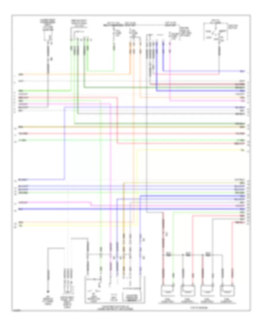
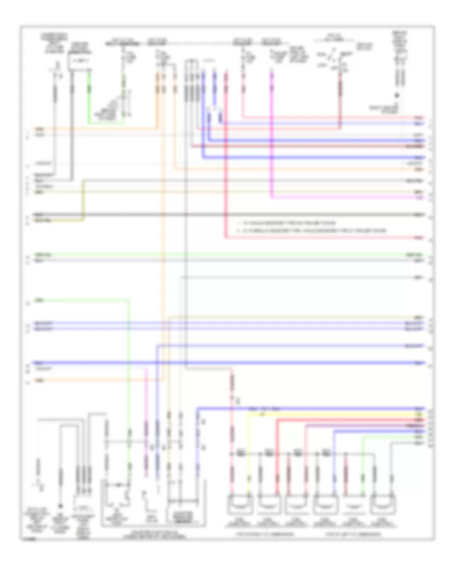
2.7L, Engine Performance Wiring Diagram (1 of 7) for Toyota Tacoma 2014
 https://portal-diagnostov.com/license.html
Automotive Electricians Portal FZCO
Automotive Electricians Portal FZCO
https://portal-diagnostov.com/license.html
https://portal-diagnostov.com/license.html
Automotive Electricians Portal FZCO
Automotive Electricians Portal FZCO
List of elements for 2.7L, Engine Performance Wiring Diagram (1 of 7) for Toyota Tacoma 2014:
- (power steering pump) power steering oil pressure switch
- +bm
- 4wd
- A/f htr fuse 15a
- A/f htr relay
- A10
- A11
- A30
- A31
- A33
- Ac1
- Accelerator position sensor (top of accelerator pedal assembly)
- Act
- Aidi
- Aip
- Air conditioning system
- Airp
- Airv
- Batt
- Bd (left rear frame rail)
- C/opn relay
- Canh
- Canl
- Computer data lines system
- Driver side j/b (left end of dash)
- E21
- E22
- Ea (right front of engine compt)
- Efi fuse 10a
- Efi main fuse 20a
- Efi main relay
- Efii
- Efio
- Els
- Els3
- Engine control module (behind right side of dash)
- Engine room j/b (left side of engine compt)
- Engine room r/b (left front of engine compt)
- Epa
- Epa2
- Fuel suction pump & gauge assembly (fuel tank)
- Hot at all times
- Ia1
- Ib1
- Igsw
- Ii1
- Imi
- Imo
- Instrument cluster system
- J/c 13 (behind right kick panel)
- J/c 14 (behind right kick panel)
- Mpmp
- Mrel
- Nsw
- Psw
- Red
- Spd
- St1-
- Sta
- Starting/charging system
- Stp
- Tach
- Transmissions system
- Transponder key ecu (left side of dash)
- Vcp2
- Vcpa
- Vpa
- Vpa2
- Vpmp
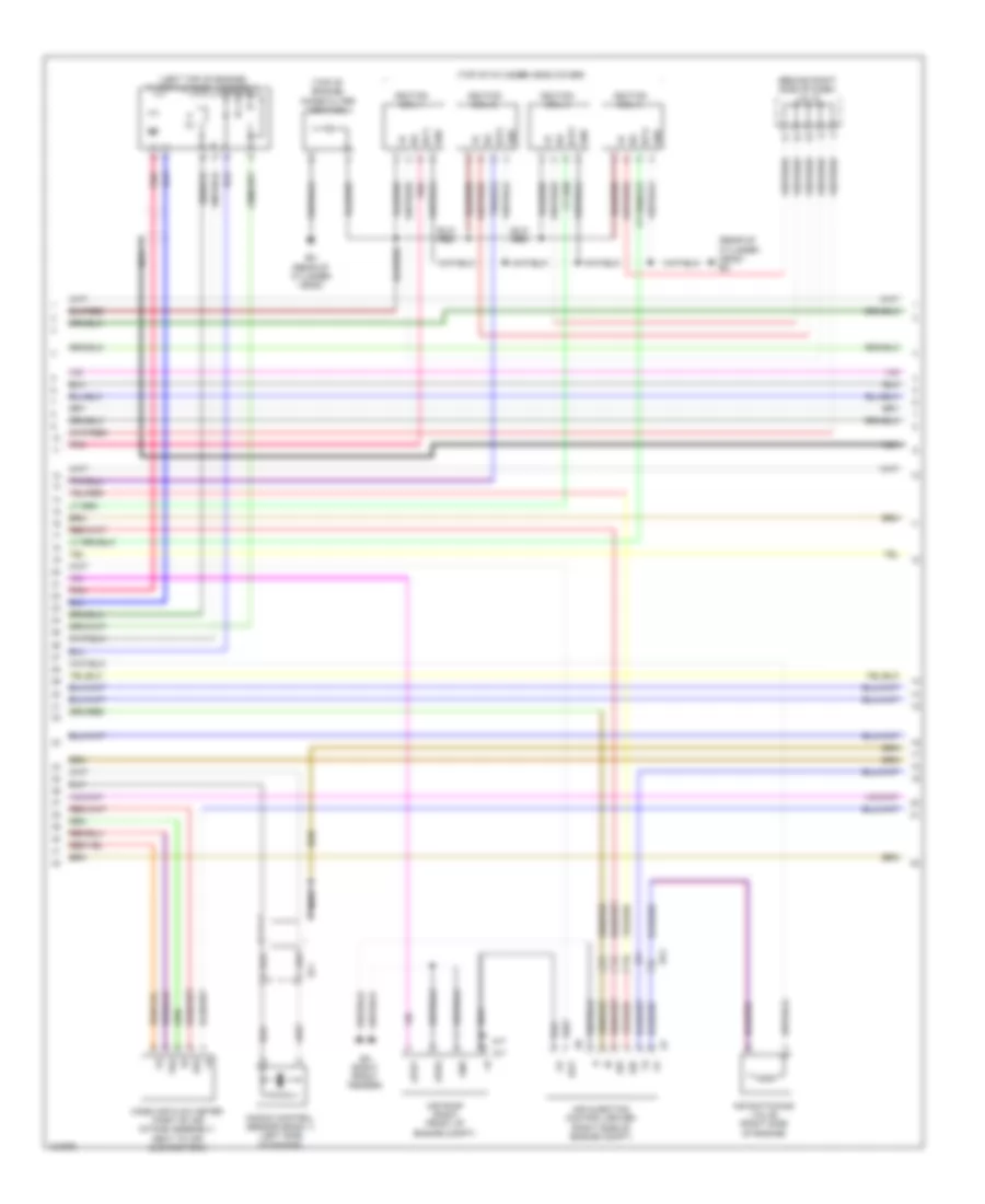
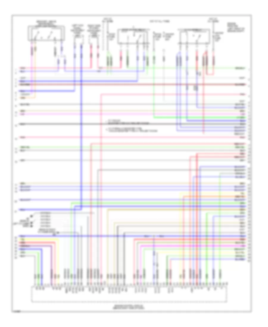
2.7L, Engine Performance Wiring Diagram (2 of 7) for Toyota Tacoma 2014
List of elements for 2.7L, Engine Performance Wiring Diagram (2 of 7) for Toyota Tacoma 2014:
- (behind right side of dash) j/c 4 & 5
- (top of engine)
- (under front passenger's seat) voltage inverter
- A17
- A18
- Acc
- B10
- B11
- C13
- Canister pressure sensor
- Canister pump module (under center of vehicle bed)
- Driver side j/b (left end of dash)
- Ea1
- Eh (rear of cylinder head)
- Fuel injector 1
- Fuel injector 2
- Fuel injector 3
- Fuel injector 4
- Gauge fuse 7.5a
- Hot at all times
- Hot in on or start
- Hot w/ tail relay energized
- I15
- Ib1
- Id2
- Ig2
- Ign fuse 15a
- Ignition switch
- Ih1
- Im1
- Instrument panel j/b 2 (right side of dash)
- Leak detection pump
- Lock
- Off
- Out
- Red
- Start
- Tail fuse 10a
- Vent valve
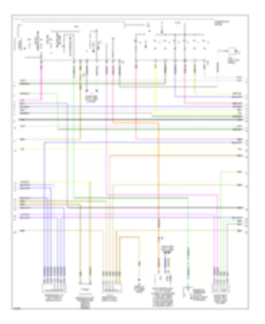
2.7L, Engine Performance Wiring Diagram (3 of 7) for Toyota Tacoma 2014
List of elements for 2.7L, Engine Performance Wiring Diagram (3 of 7) for Toyota Tacoma 2014:
- (a/t) air pump htr relay
- (automatic transmission) a/t fluid temperature sensor
- (bracket, above brake pedal) stop lamp switch
- (left kick panel) instrument panel j/b 1
- (rear of cylinder head) eg
- Air pump fuse 50a
- Air pump htr fuse 10a
- Alt
- Charging system starting/
- E01
- E02
- E17
- E20
- E2g
- Eh (rear of cylinder head)
- Eknk
- Engine control module (behind right side of dash)
- Engine room r/b (left front of engine compt)
- Eppm
- Eta
- Etcs fuse 10a
- Etha
- Ethw
- Hot at all times
- Igf1
- Igt1
- Igt2
- Igt3
- Igt4
- Knk1
- Me01
- Pnk
- Ppmp
- Red
- Stop fuse 10a
- Tha
- Thoc
- Thw
- Vcpp
- Vcta
- Vta1
- Vta2
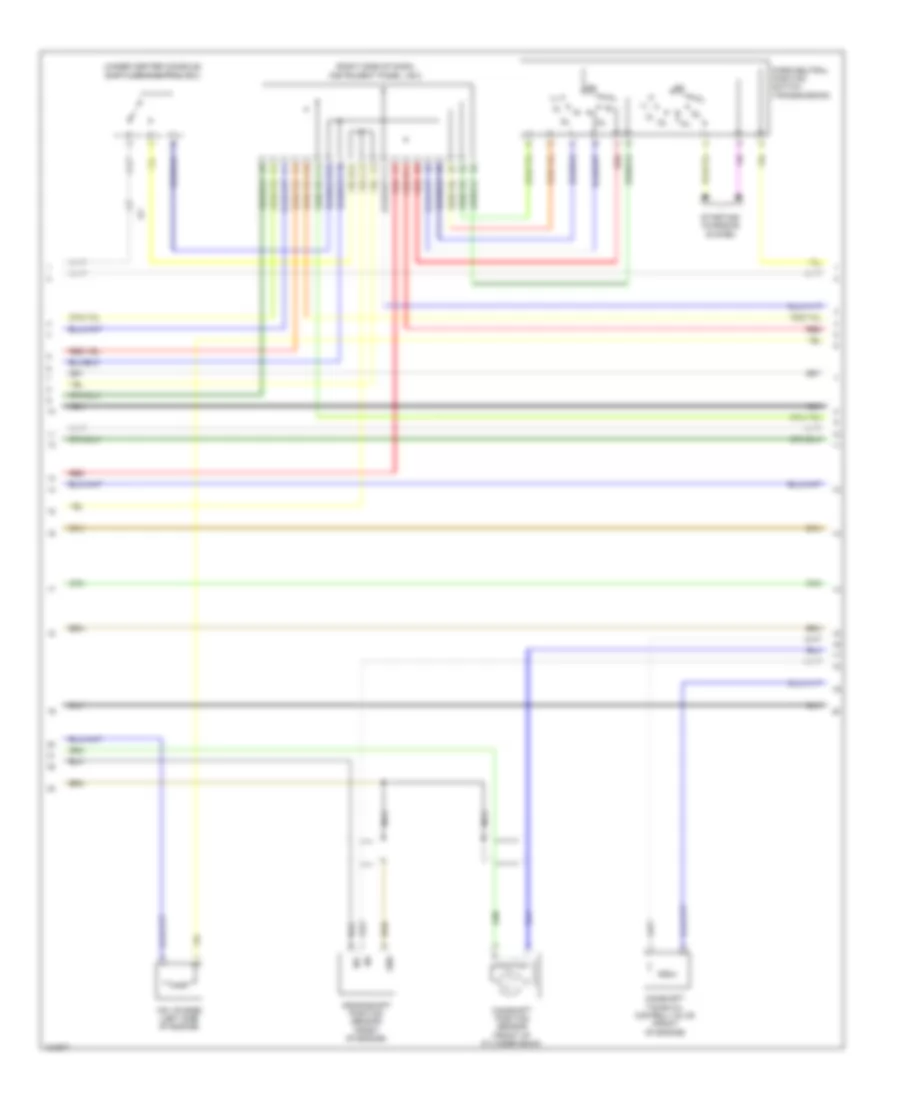
2.7L, Engine Performance Wiring Diagram (4 of 7) for Toyota Tacoma 2014
List of elements for 2.7L, Engine Performance Wiring Diagram (4 of 7) for Toyota Tacoma 2014:
- (behind right side of dash) j/c 12
- (left top of engine) throttle body assembly
- (rear of cylinder head) eh
- (right side of engine compt)
- (top of cylinder head cover)
- (top of engine)
- A/t
- Air injection control driver
- Air pump (right front of engine compt)
- Air switching valve (right side of engine)
- Aphg
- Apht
- Bat
- E2g
- Ea (right front fender)
- Ea1
- Ef1
- Eh (rear of cylinder head)
- Gnd
- Ia1
- Igf
- Ignition coil 1
- Ignition coil 2
- Ignition coil 3
- Ignition coil 4
- Igt1
- Igt2
- Igt3
- Igt4
- Knock control sensor (bank 1) (left side of engine)
- M/t
- Mass air flow meter (part of air intake assembly, next to air cleaner box)
- Nca
- Noise filter (ignition)
- Pnk
- Sip
- Siv
- Tha
2.7L, Engine Performance Wiring Diagram (5 of 7) for Toyota Tacoma 2014
List of elements for 2.7L, Engine Performance Wiring Diagram (5 of 7) for Toyota Tacoma 2014:
- A12
- A13
- A14
- A15
- A18
- B10
- Buzzer
- C10
- C12
- Canh
- Canl
- Combination meter
- Computer data lines system
- Cpu
- Eh (rear of cylinder head)
- Engine coolant temperature sensor (rear of engine)
- Engine oil pressure switch (right front of engine)
- Engine room j/b (left side of engine compt)
- Fuel ind
- Ia1
- Ind lamp malfunction
- Instrument panel j/b 2 (right side of dash)
- J/c 1 (left kick panel)
- J/c 12 (behind right side of dash)
- Nca
- Oil pressure ind
- Red
- Skid control ecu w/ actuator (hydraulic booster type: left rear of engine compt) (vacuum booster type: right rear of engine compt)
- Sp1
- Temperature ind a/t oil
2.7L, Engine Performance Wiring Diagram (6 of 7) for Toyota Tacoma 2014
List of elements for 2.7L, Engine Performance Wiring Diagram (6 of 7) for Toyota Tacoma 2014:
- (right side of dash) instrument panel j/b 2
- (under center console) shift lock control ecu
- A10
- B11
- C11
- C13
- C14
- C16
- Camshaft position sensor (front of cylinder bank)
- Camshaft timing oil control valve (front of engine)
- Crankshaft position sensor (front of engine)
- E12
- E15
- Gnd
- Ij1
- Nca
- Ne-
- Park/neutral position switch (transmission)
- Red
- Starting/ charging system
- Vsv (purge) (left side of engine)
2.7L, Engine Performance Wiring Diagram (7 of 7) for Toyota Tacoma 2014
List of elements for 2.7L, Engine Performance Wiring Diagram (7 of 7) for Toyota Tacoma 2014:
- (left side of engine compt) engine room j/b
- (left side of transmission assembly) transmission revolution sensor (turbine)
- (rear of cylinder head) eg
- (right rear of engine) air pressure sensor
- A1a+
- A1a-
- Aip
- Air fuel ratio sensor (bank 1 sensor 1) (in exhaust, upstream of catalytic converter)
- Driver side j/b (left end of dash)
- E03
- E04
- E18
- E19
- Ea1
- Eaip
- Eg (rear of cylinder head)
- Electronically controlled transmission solenoid (transmission)
- Engine control module (behind right side of dash)
- Etho
- Ex1b
- Ge01
- H13
- Ha1a
- Hai1
- Heated oxygen sensor (bank 1 sensor 2) (in exhaust, downstream of catalytic converter)
- Hot in on or start
- Ht1b
- Ig1 fuse 10a
- Ih1
- Ih2
- Nc0-
- Nca
- Nco+
- Ne+
- Ne-
- Oc1+
- Oc1-
- Ox1b
- Pnk
- Prg &
- Red
- Slt+
- Slt-
- Slu+
- Slu-
- Sp2+
- Sp2-
- Tho1
- Vehicle speed sensor (electronically controlled transmission) (transmission)
4.0L
4.0L, Engine Performance Wiring Diagram (1 of 7) for Toyota Tacoma 2014
List of elements for 4.0L, Engine Performance Wiring Diagram (1 of 7) for Toyota Tacoma 2014:
- +b2
- 4wd
- A/f htr fuse 15a
- A/f htr relay
- A10
- A11
- A30
- A31
- A33
- Ac1
- Accelerator position sensor (top of accelerator pedal assembly)
- Act
- Aip
- Aip2
- Air conditioning system
- Anti-theft system
- Batt
- Bd (left rear frame rail)
- C/opn relay
- Canh
- Canl
- Ccs
- Computer data lines system
- Cruise control system
- Driver side j/b (left end of dash)
- E13
- E14
- Ea (right front of engine compt)
- Eb (left front of engine compt)
- Efi fuse 10a
- Efi main fuse 20a
- Efi main relay
- Els
- Els2
- Engine control module (behind right side of dash)
- Engine room j/b (left side of engine compt)
- Engine room r/b (left front of engine compt)
- Epa
- Epa2
- Fpr
- Fuel pump relay
- Fuel pump resistor
- Fuel suction pump & gauge assembly (fuel tank)
- Hot at all times
- Ia1
- Ib1
- Igsw
- Ih1
- Im1
- Imi
- Imo
- Instrument cluster system
- Mpmp
- Mrel
- Red
- Spd
- St1-
- Sta
- Starting/charging system
- Stp
- Tach
- Thwo
- Transmissions system
- Vcp2
- Vcpa
- Vpa
- Vpa2
- Vpmp
4.0L, Engine Performance Wiring Diagram (2 of 7) for Toyota Tacoma 2014
List of elements for 4.0L, Engine Performance Wiring Diagram (2 of 7) for Toyota Tacoma 2014:
- (behind right side of dash) j/c 5
- (center of dash) diode (tail)
- (top of left cylinder bank)
- (top of right cylinder bank)
- (under front passenger's seat) voltage inverter
- A18
- Acc
- B10
- B11
- C13
- Canister pressure sensor
- Canister pump module (under center of vehicle bed)
- Data link connector 3 (below left center of dash)
- Driver side j/b (left end of dash)
- Ea1
- Ee (rear of right cylinder bank)
- Fuel injector 1
- Fuel injector 2
- Fuel injector 3
- Fuel injector 4
- Fuel injector 5
- Fuel injector 6
- Gauge fuse 7.5a
- H13
- Hot at all times
- Hot in on or start
- Hot w/ tail relay energized
- I15
- Ib1
- Ic (right center of dash)
- Id2
- If1
- Ig1 fuse 10a
- Ig2
- Ign fuse 15a
- Ignition switch
- Ih1
- Instrument panel j/b 2 (right side of dash)
- J/c 4 & 5 (behind right side of dash)
- Leak detection pump
- Lock
- Off
- Out
- Pnk
- Red
- Start
- Tail fuse 10a
- Vent valve
- W/ hydraulic booster type, vacuum booster type w/ trailer towing
- W/ vacuum booster type w/o trailer towing
4.0L, Engine Performance Wiring Diagram (3 of 7) for Toyota Tacoma 2014
List of elements for 4.0L, Engine Performance Wiring Diagram (3 of 7) for Toyota Tacoma 2014:
- (bracket, above brake pedal) stop lamp switch
- (left kick panel) instrument panel j/b 1
- (rear of right cylinder bank) ee
- (right side of dash) instrument panel j/b 2
- Ai valve relay
- Air pmp fuse 50a
- Air pmp htr fuse 10a
- Airv
- Booster type w/o trailer towing
- E01
- E02
- E03
- E04
- E05
- E12
- Ea1
- Ef (rear of left cylinder bank)
- Engine control module (behind right side of dash)
- Engine room r/b (left front of engine compt)
- Etcs fuse 10a
- Ex1b
- Ex2b
- Ha1a
- Ha2a
- Hot at all times
- Ht1b
- Ht2b
- Ia3
- If1
- Me01
- Ne+
- Ne-
- Oc2+
- Oc2-
- Ox1b
- Ox2b
- Pnk
- Red
- Stop fuse 10a
- Stop lp ctrl relay
- Vcv1
- Vcv2
- Vv1+
- Vv1-
- Vv2+
- Vv2-
- W/ hydraulic booster type, vacuum booster type w/ trailer towing
- W/ vacuum
4.0L, Engine Performance Wiring Diagram (4 of 7) for Toyota Tacoma 2014
List of elements for 4.0L, Engine Performance Wiring Diagram (4 of 7) for Toyota Tacoma 2014:
- (behind right side of dash) j/c 12
- (hydraulic booster type: left rear of engine compt) (vacuum booster type: right rear of engine compt) skid control ecu w/ actuator
- (rear of engine)
- (rear of right cylinder bank) ee
- (top of left cylinder bank valve cover)
- (top of right cylinder bank valve cover)
- Crankshaft position sensor (front of engine)
- Ea1
- Ed (rear of right cylinder bank)
- Gnd
- Heated oxygen sensor (bank 1 sensor 2) (in right exhaust, downstream of catalytic converter)
- Heated oxygen sensor (bank 2 sensor 2) (in left exhaust, downstream of catalytic converter)
- Ht1b
- Ht2b
- Hydraulic booster type
- If1
- Igf
- Ignition coil 1
- Ignition coil 2
- Ignition coil 3
- Ignition coil 4
- Ignition coil 5
- Ignition coil 6
- Igt1
- Igt2
- Igt3
- Igt4
- Igt5
- Igt6
- Left camshaft timing oil control valve (top front of left cylinder bank)
- Left vvt sensor (left front of engine)
- Nca
- Noise filter (ignition)
- Ox1b
- Ox2b
- Pnk
- Red
- Right vvt sensor (top right front of engine)
- Stpo
- Vacuum booster type
- Vvl+
- Vvl-
- Vvr+
- Vvr-
4.0L, Engine Performance Wiring Diagram (5 of 7) for Toyota Tacoma 2014
List of elements for 4.0L, Engine Performance Wiring Diagram (5 of 7) for Toyota Tacoma 2014:
- A/t oil tempe- rature ind
- A13
- A14
- A15
- A18
- Air pump htr relay
- B10
- C10
- Combination meter
- Cpu
- Ee (rear of right cylinder bank)
- Engine coolant temperature sensor (rear of engine)
- Engine room j/b (left side of engine compt)
- Engine room r/b 2 (left front of engine compt)
- Ih1
- Ii1
- Ij1
- J/c 1 (left kick panel)
- J/c 12 (behind right side of dash)
- J/c 4 & 5 (behind right side of dash)
- Malfunction ind lamp
- Pnk
- Red
4.0L, Engine Performance Wiring Diagram (6 of 7) for Toyota Tacoma 2014
List of elements for 4.0L, Engine Performance Wiring Diagram (6 of 7) for Toyota Tacoma 2014:
- (right front fender) ea
- (right side of dash) instrument panel j/b 2
- (right side of engine compt)
- (under center console) shift lock control ecu
- +bl
- A10
- A17
- A18
- A20
- Aip
- Aip2
- Air injection control driver
- Air pump (right front of engine compt)
- Air switching valve (bank 1)
- Air switching valve (bank 2)
- Aph+
- Aphg
- B11
- B12
- Bat
- C11
- C14
- E11
- E14
- E15
- E22
- E2g
- Ea1
- Ee (rear of right cylinder bank)
- Ee2
- Gnd
- Gndl
- If1
- Ih1
- Instrument panel j/b 2 (right side of dash)
- Knock control sensor (bank 1) (under intake manifold, on right cylinder bank)
- Knock control sensor (bank 2) (under intake manifold, on left cylinder bank)
- Mass air flow meter (part of air intake assembly, next to air cleaner box)
- Nca
- Park/neutral position switch (transmission)
- Pnk
- Red
- Sip
- Siv
- Starting/ charging system
- Tha
- Vc2
- Vsv (acis) (rear top center of engine)
- Vsv (purge) (left side of engine)
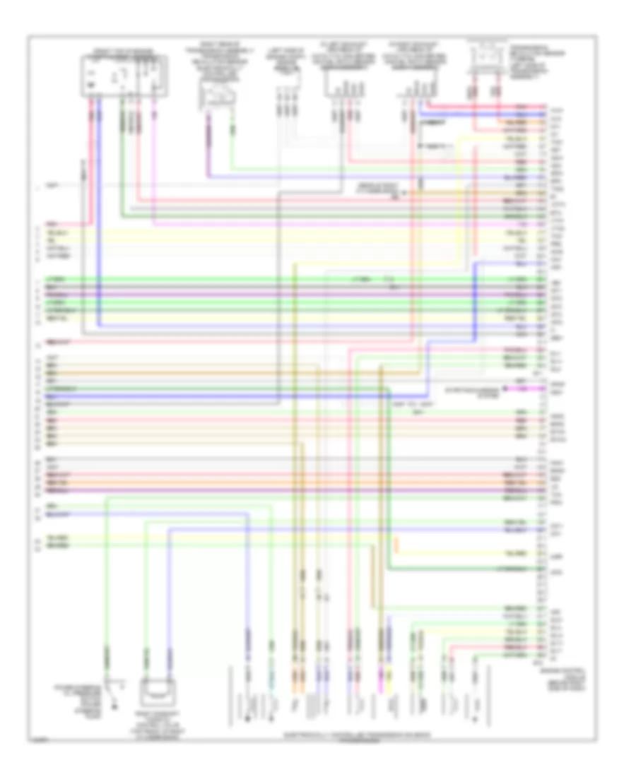
4.0L, Engine Performance Wiring Diagram (7 of 7) for Toyota Tacoma 2014
List of elements for 4.0L, Engine Performance Wiring Diagram (7 of 7) for Toyota Tacoma 2014:
- (front top of engine) throttle body assembly
- (in left exhaust, upstream of catalytic converter) air fuel ratio sensor (bank 2 sensor 1)
- (in right exhaust, upstream of catalytic converter) air fuel ratio sensor (bank 1 sensor 1)
- (left side of engine compt) engine room j/b
- (rear of right cylinder bank) ee
- (right rear of transmission assembly) transmission revolution sensor (electronically controlled transmission)
- +bm
- A1a+
- A1a-
- A2a+
- A2a-
- Acis
- Aidi
- Air1
- Airp
- E10
- E11
- E2g
- Ea1
- Ekn2
- Eknk
- Electronically controlled transmission solenoid (transmission)
- Engine control module (behind right side of dash)
- Eta
- Etha
- Ethw
- Ge01
- Ha1a
- Ha2a
- Hai1
- If1
- Igf1
- Igt1
- Igt2
- Igt3
- Igt4
- Igt5
- Igt6
- Knk1
- Knk2
- Nca
- Nsw
- Nt+
- Nt-
- Oc1+
- Oc1-
- Pnk
- Power steering oil pressure switch (power steering pump)
- Ppmp
- Prg
- Psw
- Red
- Right camshaft timing oil control valve (top front of right cylinder bank)
- Sl1+
- Sl1-
- Sl2+
- Sl2-
- Slt+
- Slt-
- Slu+
- Slu-
- Sp2+
- Sp2-
- Starting/charging system
- Th01
- Th02
- Tha
- Thw
- Transmission revolution sensor (turbine) (left side of transmission assembly)
- Vcta
- Vta1
- Vta2

 Čeština
 Dansk
Dansk Deutsch
 Ελληνικά
 English
 Español
 Suomi
Suomi Français
 Français
 עברית
עברית Hrvatski
 Magyar
 Italiano
 日本語
日本語 한국어
한국어 Nederlands
 Polski
 Português
 Português
 Română
 Русский
 Slovenčina
 Slovenščina
 Svenska
 Türkçe
 中文 (中国)