ENGINE PERFORMANCE
2.0L
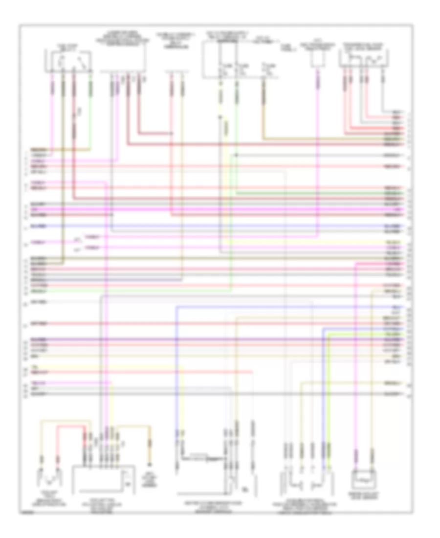
2.0L, Engine Performance Wiring Diagram, CBFA Early Production (1 of 6) for Volkswagen CC VR6 Sport 2010
 https://portal-diagnostov.com/license.html
Automotive Electricians Portal FZCO
Automotive Electricians Portal FZCO
https://portal-diagnostov.com/license.html
https://portal-diagnostov.com/license.html
Automotive Electricians Portal FZCO
Automotive Electricians Portal FZCO
List of elements for 2.0L, Engine Performance Wiring Diagram, CBFA Early Production (1 of 6) for Volkswagen CC VR6 Sport 2010:
- (on left long member) g647
- Engine control module (ecm) (in center of plenum)
- Engine coolant temperature sensor (on radiator) (integral with upper radiator hose)
- Fuse 10a
- Fuse 15a
- Fuse 20a
- Fuse 25a
- Fuse 40a
- Fuse panel b
- G645 (on firewall)
- Heater oxygen sensor 1 after catalytic converter & heated oxygen sensor 2
- Hot at all times
- Leak detection pump (ldp) (in right rear wheelwell)
- Mass air flow sensor (on engine air intake duct)
- Nca
- Radiator identification sensor
- Secondary air injection pump motor
- Secondary air injection pump relay
- Starting/charging system
- Steering column electronics control module (under side of steering column)
- T16p
- T40
- T94
- W/ adaptive cruise control
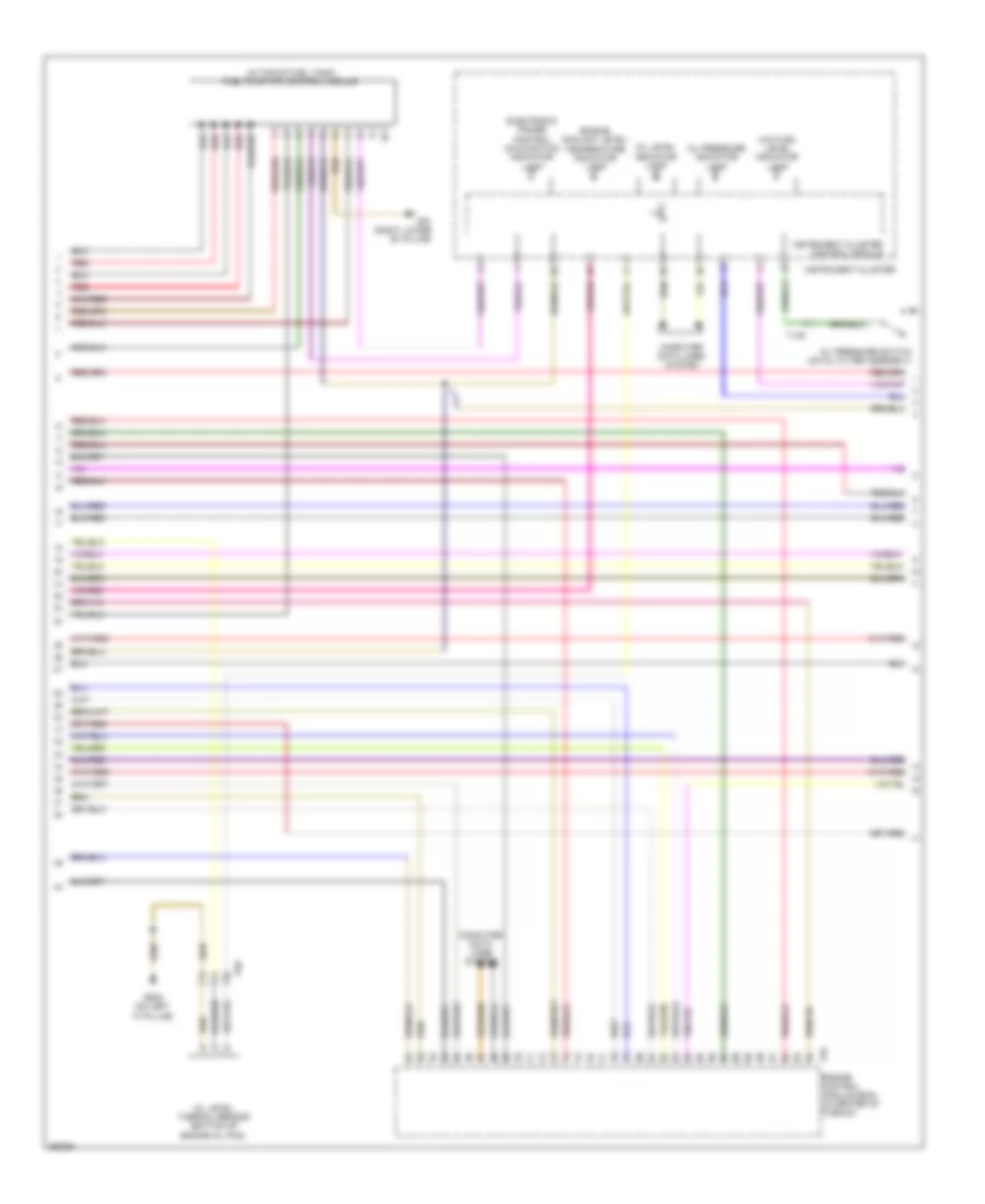
2.0L, Engine Performance Wiring Diagram, CBFA Early Production (2 of 6) for Volkswagen CC VR6 Sport 2010
List of elements for 2.0L, Engine Performance Wiring Diagram, CBFA Early Production (2 of 6) for Volkswagen CC VR6 Sport 2010:
- (a/t) dsg transmission mechatronic
- (under driver's side relay carrier) vehicle electrical system control module
- 10a
- 27a
- A/t
- Accelerator pedal position sender 2/ accelerator pedal position sensor (above accelerator pedal)
- Coolant fan (fc) control module (on coolant fan motor)
- Coolant fan 2 (behind right side of radiator)
- Engine coolant level sensor
- Fuel pump relay 2
- Fuse 10a
- Fuse 15a
- Fuse 5a
- Fuse panel c
- G671 (on left long member)
- Heated oxygen sensor (ho2s) (integral with exhaust manifold)
- Hot at all times
- M/t
- Nca
- Red
- T11
- T14c
- T16g
- T2be
- T4i
- T8t
- Transfer fuel pump/ fuel level sensor
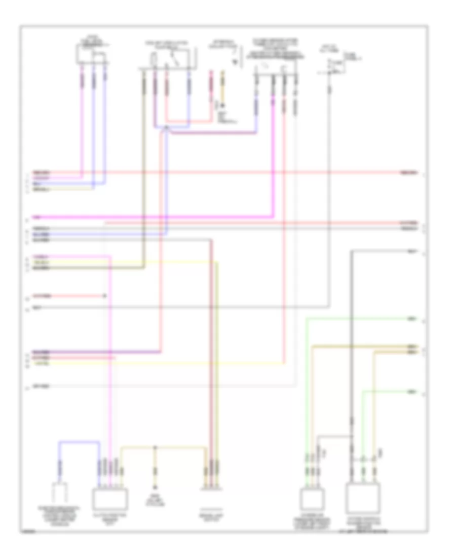
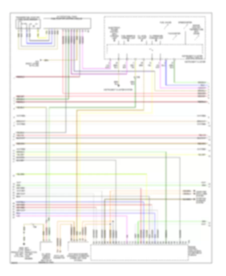
2.0L, Engine Performance Wiring Diagram, CBFA Early Production (3 of 6) for Volkswagen CC VR6 Sport 2010
List of elements for 2.0L, Engine Performance Wiring Diagram, CBFA Early Production (3 of 6) for Volkswagen CC VR6 Sport 2010:
- (in top of fuel tank) fuel pump (fp) control module
- Computer data lines system
- Electronic power control malfunction indicator lamp
- Engine control module (ecm) (in center of plenum)
- Engine coolant level/ temperature indicator lamp
- G639 (on left "a" pillar)
- G78 (right lower "b" pillar)
- Instrument cluster
- Instrument cluster control module
- Low fuel level indicator lamp
- Oil level indicator lamp
- Oil level thermal sensor (bottom of engine oil pan)
- Oil pressure indicator lamp
- Oil pressure switch (on oil filter assembly)
- Red
- T14d
- T6e
- T94
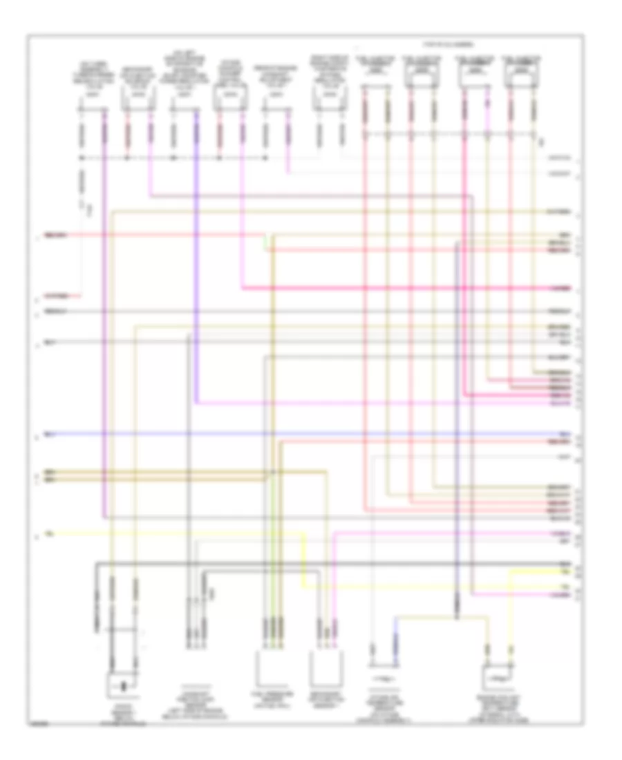
2.0L, Engine Performance Wiring Diagram, CBFA Early Production (4 of 6) for Volkswagen CC VR6 Sport 2010
List of elements for 2.0L, Engine Performance Wiring Diagram, CBFA Early Production (4 of 6) for Volkswagen CC VR6 Sport 2010:
- (awd) fuel level sensor 2
- After-run coolant pump
- Brake lamp switch
- Charge air pressure sensor (lower left front of engine compt)
- Clutch position sensor (m/t)
- Coolant circulation pump relay
- Electro-mechanical parking brake control module (under center console)
- Fuse 50a
- Fuse panel a
- G639 (on left "a" pillar)
- G647 (on firewall)
- Hot at all times
- Intake manifold runner position sensor (at left rear of engine)
- Nca
- Oxygen sensor after three way catalytic converter/ heater oxygen sensor 2 after catalytic converter
- T14c
- T2ck
- T6bu
2.0L, Engine Performance Wiring Diagram, CBFA Early Production (5 of 6) for Volkswagen CC VR6 Sport 2010
List of elements for 2.0L, Engine Performance Wiring Diagram, CBFA Early Production (5 of 6) for Volkswagen CC VR6 Sport 2010:
- (on left side of engine) evaporative emission (evap) canister purge regulator valve 1
- (on turbo assembly) turbocharger recirculating valve
- (rear of engine) camshaft adjustment valve 1
- (right side of engine compt) wastegate bypass regulator valve
- (top of cylinders) fuel injectors
- Camshaft position (cmp) sensor (left side of engine below intake manifold)
- Cylinder 1
- Cylinder 2
- Cylinder 3
- Cylinder 4
- Engine coolant temperature (ect) sensor
- Fuel pressure sensor (on fuel rail)
- Intake air temperature sensor (on intake manifold assembly)
- Intake manifold runner control (imrc) valve
- Knock sensor 1 (below intake manifold)
- Nca
- Secondary air injection sensor 1
- Secondary air injection solenoid valve
- T14c
- T6bu
- T8y
- W/ adaptive cruise control
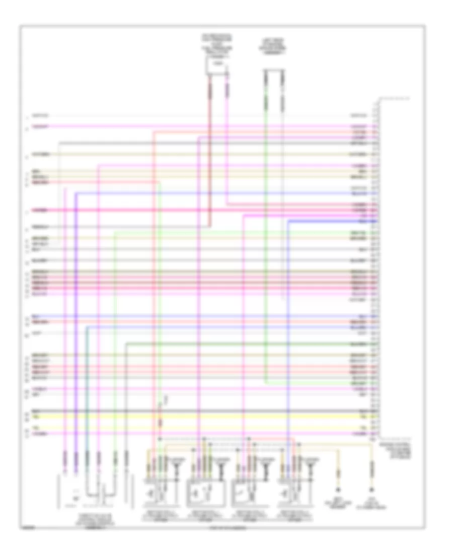
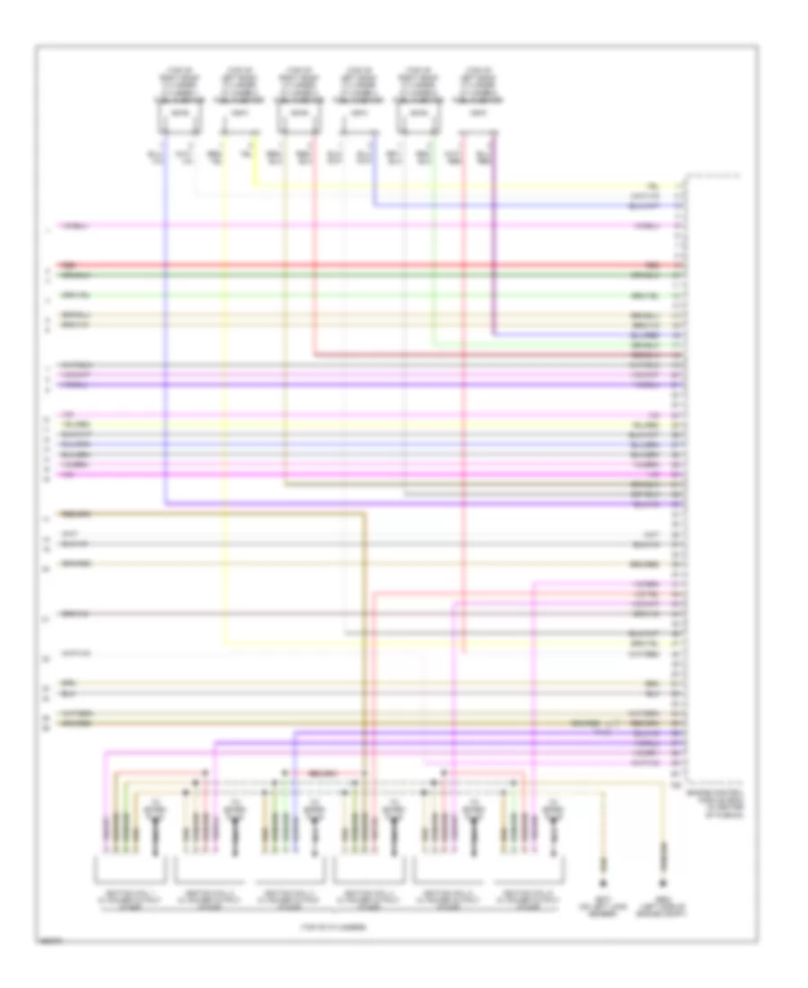
2.0L, Engine Performance Wiring Diagram, CBFA Early Production (6 of 6) for Volkswagen CC VR6 Sport 2010
List of elements for 2.0L, Engine Performance Wiring Diagram, CBFA Early Production (6 of 6) for Volkswagen CC VR6 Sport 2010:
- (left rear of engine) engine speed sensor
- (on mechanical high pressure pump) fuel pressure regulator valve
- (top of cylinders)
- Engine control module (ecm) (in center of plenum)
- Epc throttle drive angle sensor 1 & 2
- G15
- G673 (on left long member)
- Ignition coil 1 w/ power output stage
- Ignition coil 2 w/ power output stage
- Ignition coil 3 w/ power output stage
- Ignition coil 4 w/ power output stage
- Nca
- T14c
- T60
- To spark plug
2.0L, Engine Performance Wiring Diagram, CBFA Late Production (1 of 6) for Volkswagen CC VR6 Sport 2010
List of elements for 2.0L, Engine Performance Wiring Diagram, CBFA Late Production (1 of 6) for Volkswagen CC VR6 Sport 2010:
- (on firewall) g647
- A/t
- Cooling fans system
- Dsg transmission mechatronic
- Engine control module (ecm) (in center of plenum)
- Engine coolant temperature sensor (on radiator) (integral with upper radiator hose)
- Fuse 10a
- Fuse 15a
- Fuse 20a
- Fuse 25a
- Fuse 40a
- Fuse 5a
- Fuse panel b
- G645 (on firewall)
- Hot at all times
- Leak detection pump (ldp) (usa) (in right rear wheelwell)
- M/t
- Mass air flow sensor (on engine air intake duct)
- Nca
- Oxygen sensor after three way catalytic converter (twc)/ heater oxygen sensor 1 after catalytic converter
- Red
- Secondary air injection pump motor
- Starting/charging system
- Steering column electronic systems control module (under side of steering column)
- T16o
- T40
- T94
- W/ adaptive cruise control
2.0L, Engine Performance Wiring Diagram, CBFA Late Production (2 of 6) for Volkswagen CC VR6 Sport 2010
List of elements for 2.0L, Engine Performance Wiring Diagram, CBFA Late Production (2 of 6) for Volkswagen CC VR6 Sport 2010:
- (under driver's side relay carrier) vehicle electrical system control module
- 10a
- 27a
- Accelerator pedal position sender 2 (above accelerator pedal)
- Coolant fan 2 (behind right side of radiator)
- Coolant fan control module (on coolant fan motor)
- Engine coolant level sensor
- Fuse 10a
- Fuse 20a
- Fuse panel c
- G671 (on left long member)
- Heated oxygen sensor (ho2s) (integral with exhaust manifold)
- Heater oxygen sensor 2 after catalytic converter & heated oxygen sensor 2
- Hot at all times
- Nca
- Red
- T2be
- T4i
- T52b
- T52c
- Transfer fuel pump/ fuel level sensor
2.0L, Engine Performance Wiring Diagram, CBFA Late Production (3 of 6) for Volkswagen CC VR6 Sport 2010
List of elements for 2.0L, Engine Performance Wiring Diagram, CBFA Late Production (3 of 6) for Volkswagen CC VR6 Sport 2010:
- (in top of fuel tank) fuel pump (fp) control module
- Computer data lines system
- Electronic power control malfunction indicator lamp
- Engine control module (ecm) (in center of plenum)
- Engine coolant level/ temperature indicator lamp
- Engine coolant temperature (ect) gauge
- Fuel gauge
- G639 (on left "a" pillar)
- G78 (right lower "b" pillar)
- Instrument cluster
- Instrument cluster control module
- Low fuel level indicator lamp
- Oil level indicator lamp
- Oil level thermal sensor (canada) (bottom of engine oil pan)
- Oil pressure indicator lamp
- Red
- T94
- Tachometer
2.0L, Engine Performance Wiring Diagram, CBFA Late Production (4 of 6) for Volkswagen CC VR6 Sport 2010
List of elements for 2.0L, Engine Performance Wiring Diagram, CBFA Late Production (4 of 6) for Volkswagen CC VR6 Sport 2010:
- (awd) fuel level sensor 2
- Brake light switch
- Charge air pressure sensor/ manifold absolute pressure sensor (lower left front of engine compt)
- Clutch position sensor (m/t)
- Electro-mechanical parking brake control module (under center console)
- Fuel pump relay 2
- Fuse 50a
- Fuse panel a
- G639 (on left "a" pillar)
- G645 (on firewall)
- Hot at all times
- Intake manifold runner position sensor (at left rear of engine)
- Oil pressure switch (on oil filter assembly)
- T14a
- T6bu
2.0L, Engine Performance Wiring Diagram, CBFA Late Production (5 of 6) for Volkswagen CC VR6 Sport 2010
List of elements for 2.0L, Engine Performance Wiring Diagram, CBFA Late Production (5 of 6) for Volkswagen CC VR6 Sport 2010:
- (on left side of engine) evaporative emission (evap) canister purge regulator valve 1
- (on turbo assembly) turbocharger recirculating valve
- (rear of engine) camshaft adjustment valve 1
- (right side of engine compt) wastegate bypass regulator valve
- (top of cylinders)
- Camshaft position (cmp) sensor (left side of engine below intake manifold)
- Engine coolant temperature (ect) sensor (integral with upper radiator hose)
- Fuel injector cylinder 1
- Fuel injector cylinder 2
- Fuel injector cylinder 3
- Fuel injector cylinder 4
- Fuel pressure sensor (on fuel rail)
- Intake air temperature sensor (on intake manifold assembly)
- Intake manifold runner control (imrc) valve
- Knock sensor 1 (below intake manifold)
- Nca
- Secondary air injection sensor 1
- Secondary air injection solenoid valve
- T14a
- T6bu
- T8y
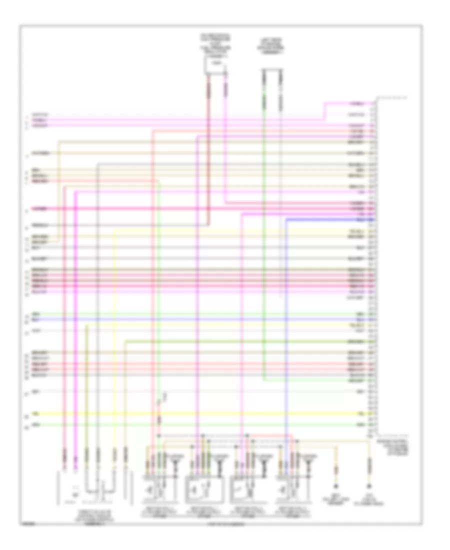
2.0L, Engine Performance Wiring Diagram, CBFA Late Production (6 of 6) for Volkswagen CC VR6 Sport 2010
List of elements for 2.0L, Engine Performance Wiring Diagram, CBFA Late Production (6 of 6) for Volkswagen CC VR6 Sport 2010:
- (left rear of engine) engine speed sensor
- (on mechanical high pressure pump) fuel pressure regulator valve
- (top of cylinders)
- Engine control module (ecm) (in center of plenum)
- G15 (top of cylinder head)
- G673 (on left long member)
- Ignition coil 1 w/ power output stage
- Ignition coil 2 w/ power output stage
- Ignition coil 3 w/ power output stage
- Ignition coil 4 w/ power output stage
- Nca
- Red
- T14a
- T60
- Throttle valve control module (on intake manifold assembly)
- To spark plug
2.0L, Engine Performance Wiring Diagram, CCTA (1 of 6) for Volkswagen CC VR6 Sport 2010
List of elements for 2.0L, Engine Performance Wiring Diagram, CCTA (1 of 6) for Volkswagen CC VR6 Sport 2010:
- (on firewall) g647
- A/t
- Cooling fans system
- Dsg transmission mechatronic
- Engine control module (ecm) (in center of plenum)
- Engine coolant temperature sensor (on radiator) (integral with upper radiator hose)
- Fuse 10a
- Fuse 15a
- Fuse 20a
- Fuse 25a
- Fuse 40a
- Fuse 5a
- Fuse panel b
- G645 (on firewall)
- Hot at all times
- Leak detection pump (ldp) (usa) (in right rear wheelwell)
- M/t
- Mass air flow sensor (on engine air intake duct)
- Nca
- Oxygen sensor after three way catalytic converter (twc)/ heater oxygen sensor 1 after catalytic converter
- Red
- Reduced oil pressure switch (on oil filter assembly)
- Secondary air injection pump motor
- Starting/ charging system
- Starting/charging system
- Steering column electronic systems control module (under side of steering column)
- T14a
- T16o
- T40
- T94
- W/ adaptive cruise control
2.0L, Engine Performance Wiring Diagram, CCTA (2 of 6) for Volkswagen CC VR6 Sport 2010
List of elements for 2.0L, Engine Performance Wiring Diagram, CCTA (2 of 6) for Volkswagen CC VR6 Sport 2010:
- (under driver's side relay carrier) vehicle electrical system control module
- 10a
- 27a
- Accelerator pedal position sender 2 (above accelerator pedal)
- Coolant fan 2 (behind right side of radiator)
- Coolant fan control module (on coolant fan motor)
- Engine coolant level sensor
- Fuse 10a
- Fuse 20a
- Fuse panel c
- G671 (on left long member)
- Heated oxygen sensor (ho2s) (integral with exhaust manifold)
- Heater oxygen sensor 2 after catalytic converter/ heated oxygen sensor 2
- Hot at all times
- Nca
- Red
- T2be
- T4i
- T52b
- T52c
- Transfer fuel pump/ fuel level sensor
2.0L, Engine Performance Wiring Diagram, CCTA (3 of 6) for Volkswagen CC VR6 Sport 2010
List of elements for 2.0L, Engine Performance Wiring Diagram, CCTA (3 of 6) for Volkswagen CC VR6 Sport 2010:
- (in top of fuel tank) fuel pump (fp) control module
- Computer data lines system
- Electronic power control malfunction indicator lamp
- Engine control module (ecm) (in center of plenum)
- Engine coolant level/ temperature indicator lamp
- Engine coolant temperature (ect) gauge
- Fuel gauge
- G639 (on left "a" pillar)
- G78 (right lower "b" pillar)
- Instrument cluster
- Instrument cluster control module
- Low fuel level indicator lamp
- Oil level indicator lamp
- Oil level thermal sensor (bottom of engine oil pan)
- Oil pressure indicator lamp
- Red
- T6e
- T94
- Tachometer
2.0L, Engine Performance Wiring Diagram, CCTA (4 of 6) for Volkswagen CC VR6 Sport 2010
List of elements for 2.0L, Engine Performance Wiring Diagram, CCTA (4 of 6) for Volkswagen CC VR6 Sport 2010:
- (awd) fuel level sensor 2
- Brake light switch
- Charge air pressure sensor/ manifold absolute pressure sensor (lower left front of engine compt)
- Clutch position sensor (m/t)
- Electro-mechanical parking brake control module (under center console)
- Fuel pump relay 2
- Fuse 50a
- Fuse panel a
- G639 (on left "a" pillar)
- G645 (on firewall)
- Hot at all times
- Intake manifold runner position sensor (at left rear of engine)
- Oil pressure switch (on oil filter assembly)
- T14a
- T6bu
2.0L, Engine Performance Wiring Diagram, CCTA (5 of 6) for Volkswagen CC VR6 Sport 2010
List of elements for 2.0L, Engine Performance Wiring Diagram, CCTA (5 of 6) for Volkswagen CC VR6 Sport 2010:
- (on left side of engine) evaporative emission (evap) canister purge regulator valve 1
- (on turbo assembly) turbocharger recirculation valve
- (rear of engine) camshaft adjustment valve 1
- (right side of engine compt) wastegate bypass regulator valve
- (top of cylinders)
- Camshaft position (cmp) sensor (left side of engine below intake manifold)
- Cylinder 4
- Engine coolant temperature (ect) sensor (integral with upper radiator hose)
- Fuel injectors
- Fuel injectors cylinder 1
- Fuel injectors cylinder 2
- Fuel injectors cylinder 3
- Fuel pressure sensor (on fuel rail)
- Intake air temperature sensor (on intake manifold assembly)
- Intake manifold runner control (imrc) valve
- Knock sensor 1 (below intake manifold)
- Nca
- Oil pressure regulation valve
- T14a
- T6bu
- T8y
2.0L, Engine Performance Wiring Diagram, CCTA (6 of 6) for Volkswagen CC VR6 Sport 2010
List of elements for 2.0L, Engine Performance Wiring Diagram, CCTA (6 of 6) for Volkswagen CC VR6 Sport 2010:
- (left rear of engine) engine speed sensor
- (on mechanical high pressure pump) fuel pressure regulator valve
- (top of cylinders)
- Engine control module (ecm) (in center of plenum)
- G15 (top of cylinder head)
- G673 (on left long member)
- Ignition coil 1 w/ power output stage
- Ignition coil 2 w/ power output stage
- Ignition coil 3 w/ power output stage
- Ignition coil 4 w/ power output stage
- Nca
- Red
- T14a
- T60
- Throttle valve control module (on intake manifold assembly)
- To spark plug
3.6L
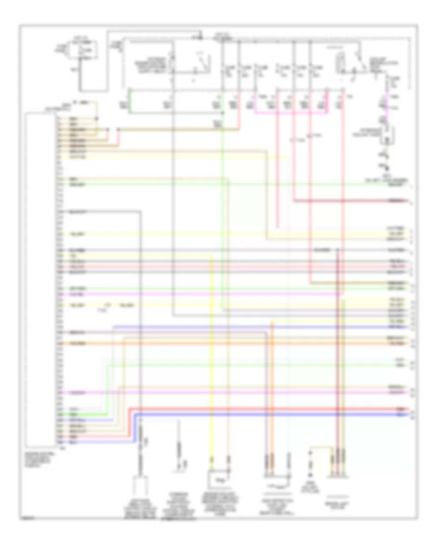
3.6L, Engine Performance Wiring Diagram, BLV (1 of 6) for Volkswagen CC VR6 Sport 2010
List of elements for 3.6L, Engine Performance Wiring Diagram, BLV (1 of 6) for Volkswagen CC VR6 Sport 2010:
- After-run coolant pump
- Brake light switch
- Coolant recirculation pump relay
- Distance regulation control module (behind center of front grille)
- Engine control module (ecm) (in center of plenum)
- Engine coolant temperature (ect) sensor (radiator) (integral with upper radiator hose)
- Fuse 10a
- Fuse 125a
- Fuse 15a
- Fuse 20a
- Fuse 25a
- Fuse 5a
- Fuse panel b
- Fuse panel f
- G639 (on left "a" pillar)
- G645 (on firewall)
- G673 (on left long member)
- Hot at all times
- Leak detection pump (ldp) (in right rear wheelwell)
- Red
- Steering column electronic systems control module (under side of steering column)
- T10a
- T14a
- T20d
- T26a
- T40
- T94
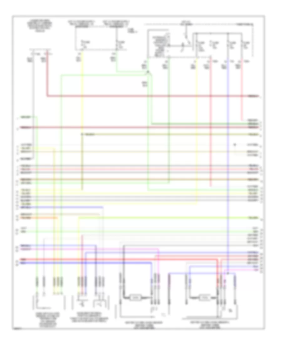
3.6L, Engine Performance Wiring Diagram, BLV (2 of 6) for Volkswagen CC VR6 Sport 2010
List of elements for 3.6L, Engine Performance Wiring Diagram, BLV (2 of 6) for Volkswagen CC VR6 Sport 2010:
- (under driver's side relay carrier) vehicle electrical system control module
- 10a
- Accelerator pedal position sensor 2/ throttle position (tp) sensor (above accelerator pedal)
- Fuse 10a
- Fuse 10a (usa)
- Fuse 15a
- Fuse 5a
- Fuse panel b
- Fuse panel c
- Heated oxygen (ho2s) sensor (before three way converter)
- Heated oxygen (ho2s) sensor 2 (before three way converter)
- Hot at all times
- Mass air flow (maf) sensor/ intake air temperature (iat) sensor (on engine air intake duct)
- Nca
- Nca nca
- Red
- T11
- T16g
- T26a
- T40
3.6L, Engine Performance Wiring Diagram, BLV (3 of 6) for Volkswagen CC VR6 Sport 2010
List of elements for 3.6L, Engine Performance Wiring Diagram, BLV (3 of 6) for Volkswagen CC VR6 Sport 2010:
- (in top of fuel tank) fuel pump (fp) control module
- Computer data lines system
- Data bus on board diagnostic interface (under left side of dash)
- Data link connector
- Electronic power control (epc) warning lamp
- Engine control module (ecm) (in center of plenum)
- Engine coolant temperature (ect) gauge
- Fuel gauge
- Fuel reserve warning lamp
- G671 g639 (late (early production) (on left long member)
- G78 (right lower "b" pillar)
- Instrument cluster
- Instrument cluster control module
- Instrument cluster system
- Oil level ind lamp
- Oil level thermal sensor (bottom of engine oil pan)
- Oil pressure warning lamp
- Production) (on left "a" pillar)
- Speedometer
- Starting/ charging system
- T6e
- T94
- Tachometer
- Transfer fuel pump (fp)/ fuel level sensor
3.6L, Engine Performance Wiring Diagram, BLV (4 of 6) for Volkswagen CC VR6 Sport 2010
List of elements for 3.6L, Engine Performance Wiring Diagram, BLV (4 of 6) for Volkswagen CC VR6 Sport 2010:
- (awd) fuel level sensor 2
- 27a
- Coolant fan 2 (behind right side of radiator)
- Coolant fan control (fc) module (on coolant fan motor)
- Fuse 15a
- Fuse 50a
- Fuse panel a
- Fuse panel c
- G671 (on left long member)
- G673 (on left long member)
- Hot at all times
- Nca
- Oil pressure switch (on oil filter assembly)
- Oxygen sensor 2 behind three way catalytic converter (behind left catalytic converter)
- Oxygen sensor behind three way catalytic converter (behind right catalytic converter)
- Positive crankcase ventilation (pcv) heating element (on intake manifold)
- Red
- T14a
- T2be
- T4i
3.6L, Engine Performance Wiring Diagram, BLV (5 of 6) for Volkswagen CC VR6 Sport 2010
List of elements for 3.6L, Engine Performance Wiring Diagram, BLV (5 of 6) for Volkswagen CC VR6 Sport 2010:
- (on high pressure pump) fuel pressure regulator valve
- (on left side of engine) evaporative emission (evap) canister purge regulator valve 1
- (rear of engine) camshaft adjustment valve 1
- (rear of engine) camshaft adjustment valve 1 (exhaust)
- (rear of right cylinder bank) camshaft position (cmp) sensor 2
- (right front of engine) low fuel pressure sensor
- Camshaft position (cmp) sensor (rear of left cylinder bank)
- Engine coolant temperature (ect) sensor
- Engine speed (rpm) sensor (left rear of engine)
- Fuel pressure sensor (rear of left fuel rail)
- Knock sensor (ks) 1 (between cylinders 1 & 3)
- Knock sensor (ks) 2 (between cylinders 4 & 6)
- Nca
- Red
- T14a
- Throttle valve control module (on intake manifold)
3.6L, Engine Performance Wiring Diagram, BLV (6 of 6) for Volkswagen CC VR6 Sport 2010
List of elements for 3.6L, Engine Performance Wiring Diagram, BLV (6 of 6) for Volkswagen CC VR6 Sport 2010:
- (top of cylinders)
- (top of left bank cylinder) cylinder 2 fuel injector
- (top of left bank cylinder) cylinder 4 fuel injector
- (top of left bank cylinder) cylinder 6 fuel injector
- (top of right bank cylinder) cylinder 1 fuel injector
- (top of right bank cylinder) cylinder 3 fuel injector
- (top of right bank cylinder) cylinder 5 fuel injector
- Engine control module (ecm) (in center of plenum)
- G652 (left side of engine compt)
- G673 (on left long member)
- Ignition coil 1 w/ power output stage
- Ignition coil 2 w/ power output stage
- Ignition coil 3 w/ power output stage
- Ignition coil 4 w/ power output stage
- Ignition coil 5 w/ power output stage
- Ignition coil 6 w/ power output stage
- Nca
- Red
- T14a
- T60
- To spark plug

 Čeština
 Dansk
Dansk Deutsch
 Ελληνικά
 English
 Español
 Suomi
Suomi Français
 Français
 עברית
עברית Hrvatski
 Magyar
 Italiano
 日本語
日本語 한국어
한국어 Nederlands
 Polski
 Português
 Português
 Română
 Русский
 Slovenčina
 Slovenščina
 Svenska
 Türkçe
 中文 (中国)