ENGINE PERFORMANCE
2.0L
2.0L, Engine Performance Wiring Diagrams (1 of 3) for Volkswagen Golf GL 1999
 https://portal-diagnostov.com/license.html
Automotive Electricians Portal FZCO
Automotive Electricians Portal FZCO
https://portal-diagnostov.com/license.html
https://portal-diagnostov.com/license.html
Automotive Electricians Portal FZCO
Automotive Electricians Portal FZCO
List of elements for 2.0L, Engine Performance Wiring Diagrams (1 of 3) for Volkswagen Golf GL 1999:
- (at right of air cleaner housing, in intake air duct)
- (on center of firewall)
- Air conditioning system
- Anti-lock brake system
- Evaporative emission (evap) canister purge regulator valve (next to engine coolant reservoir)
- Fuse 10a
- Fuse panel
- G121
- Heated oxygen sensor (ho2s) (ahead of 3-way catalytic converter)
- Hot at all times
- Instrument cluster
- Leak detection pump (in right rear wheelhousing)
- Malfunction indicator light (mil)
- Mass airflow (maf) sensor & intake air temperature (iat) sensor
- Motronic engine control module (ecm) (at base of windshield, in center plenum)
- Oxygen sensor (o2s) (at back of 3-way catalytic converter)
- Secondary air injection (air) solenoid valve (above brake fluid reservoir)
- T32
- T32a
- Transmission controls system
2.0L, Engine Performance Wiring Diagrams (2 of 3) for Volkswagen Golf GL 1999
List of elements for 2.0L, Engine Performance Wiring Diagrams (2 of 3) for Volkswagen Golf GL 1999:
- (center of firewall) g121
- (right side of firewall) g123
- Data link connector (dlc) (under left side of dash)
- Engine speed (rpm) sensor (left side of of engine)
- Fuel pump
- Fuel pump relay
- Fuse 15a
- Fuse 28 10a
- Fuse 32 10a
- Fuse 34 10a
- Fuse 43 10a
- Fuse 50a
- Fuse bracket
- Fuse panel
- G202 (behind left side of dash)
- Hot at all times
- Hot in run or start
- Ignition switch
- Knock sensor (ks) 1 (left front side of engine)
- Knock sensor (ks) 2 (left side of engine, behind ignition coil)
- Nca
- Off
- Positive crankcase ventilation (pvc) heating element (in fresh air intake hose)
- Red
- Relay panel
- Run
- S3/3
- S3/6
- Secondary air injection (air) pump relay (at left side of engine compt, behind air cleaner housing)
- Secondary air injection pump motor (left rear side of engine)
- Start
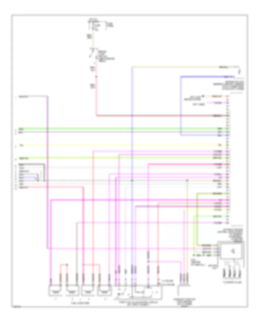
2.0L, Engine Performance Wiring Diagrams (3 of 3) for Volkswagen Golf GL 1999
List of elements for 2.0L, Engine Performance Wiring Diagrams (3 of 3) for Volkswagen Golf GL 1999:
- (not used)
- Anti-lock brake system
- Brake- light switch (above brake pedal)
- Camshaft position (cmp) sensor (on cylinder head)
- Engine coolant temperature (ect) sensor (on cylinder head, in coolant flange)
- Fuel injectors
- Fuse 10a
- Fuse panel
- G121 (center of firewall)
- Hot at all times
- Ignition coil
- Motronic engine control module (ecm) (at base of windshield, in center plenum)
- Nca
- Throttle valve control module (on throttle body)
- To spark plugs
- W/ cruise
- W/o cruise

 Čeština
 Dansk
Dansk Deutsch
 Ελληνικά
 English
 Español
 Suomi
Suomi Français
 Français
 עברית
עברית Hrvatski
 Magyar
 Italiano
 日本語
日本語 한국어
한국어 Nederlands
 Polski
 Português
 Português
 Română
 Русский
 Slovenčina
 Slovenščina
 Svenska
 Türkçe
 中文 (中国)