ENGINE PERFORMANCE
1.9L
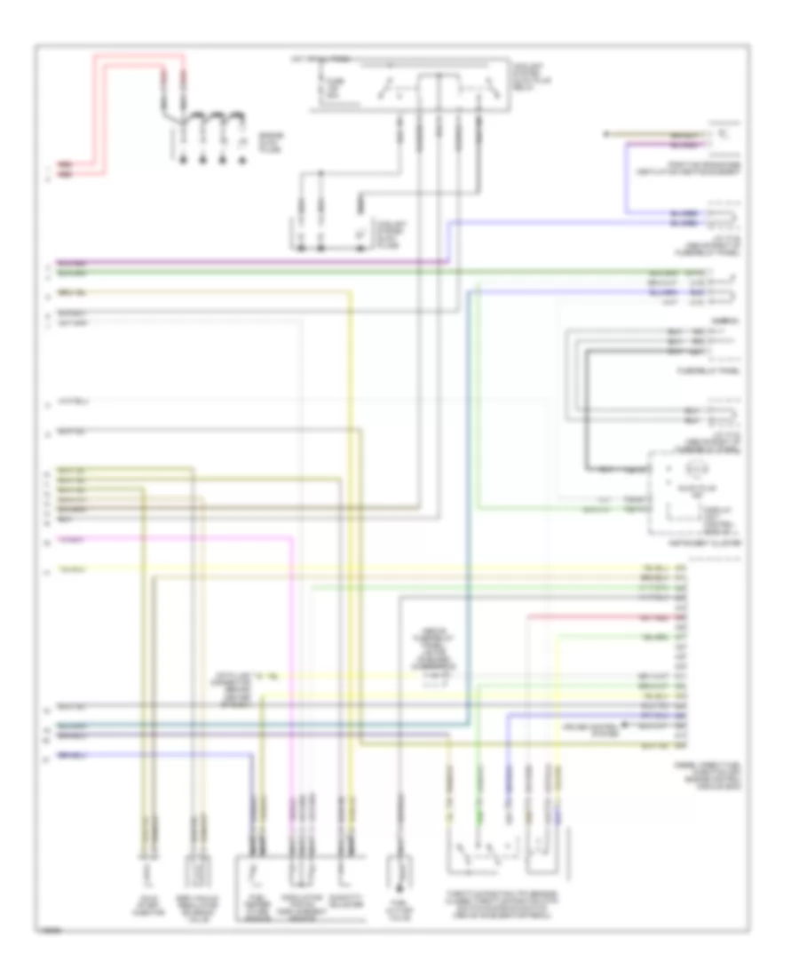
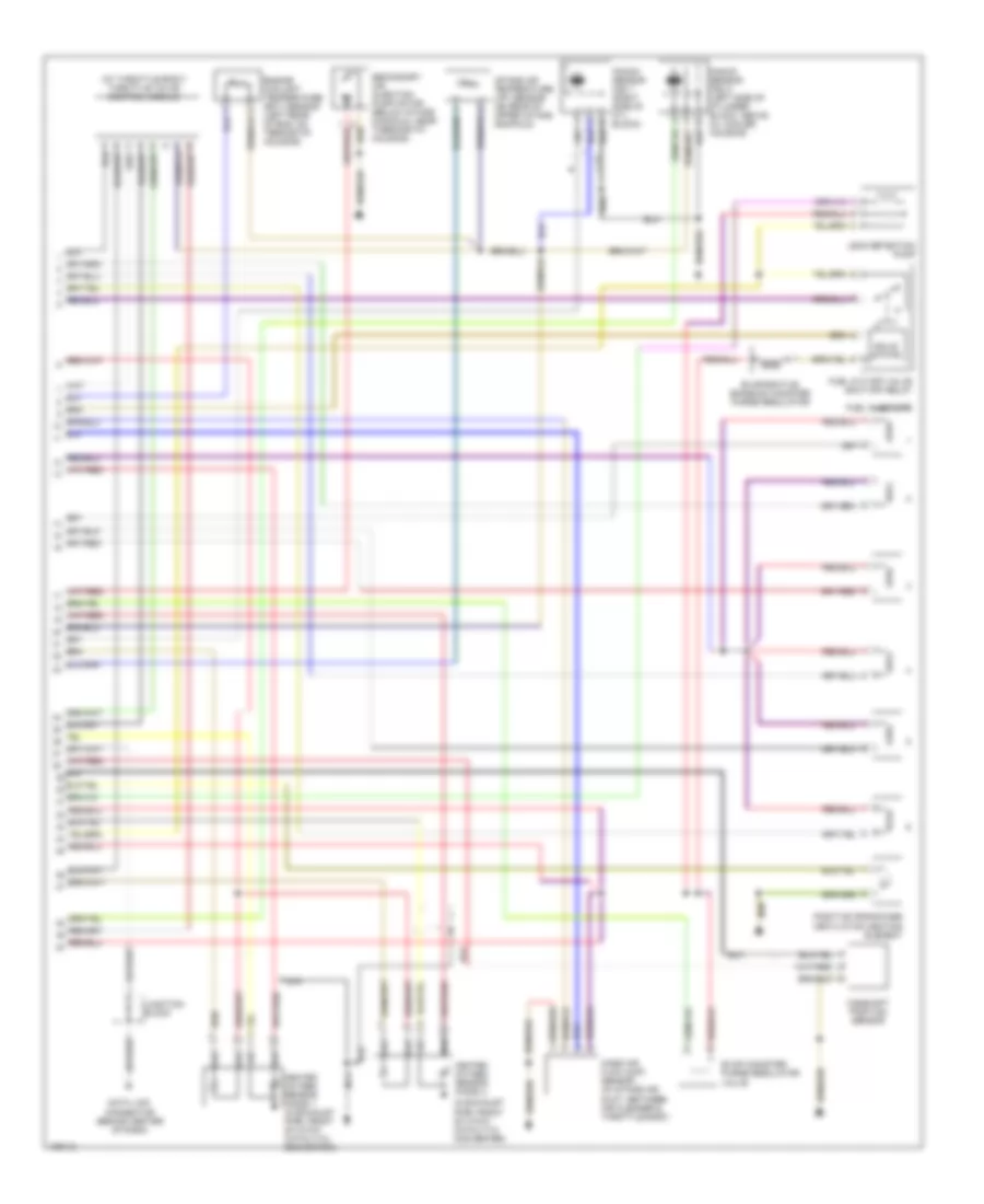
1.9L Turbo Diesel, Engine Performance Wiring Diagrams (1 of 2) for Volkswagen Jetta GL 1998
 https://portal-diagnostov.com/license.html
Automotive Electricians Portal FZCO
Automotive Electricians Portal FZCO
https://portal-diagnostov.com/license.html
https://portal-diagnostov.com/license.html
Automotive Electricians Portal FZCO
Automotive Electricians Portal FZCO
List of elements for 1.9L Turbo Diesel, Engine Performance Wiring Diagrams (1 of 2) for Volkswagen Jetta GL 1998:
- (not used)
- (on brake pedal) brake light switch
- 0.3 bar oil pressure switch
- 30a
- A/c system
- Battery
- Brake switch (on brake pedal)
- Clutch vacuum vent valve switch (on clutch pedal bracket)
- Cooling fans system
- Cruise control system
- D/11
- Diesel direct fuel injection (dfi) engine control module (ecm)
- E/3
- E/4
- Engine speed sensor
- Engine temperature sensor
- Fuse 10a
- Fuse/ relay panel
- G1/10
- G1/4
- G1/7
- Generator
- Glow plug fuse
- Glow plug relay
- Hot at all times
- Ignition
- Instrument cluster system
- Intake air temperature sensor
- J/c (tv11) (above right of fuse/relay panel)
- Mass air flow sensor
- Needle lift sensor
- Red
- Red red
- W/4
- Wastegate bypass regulator valve
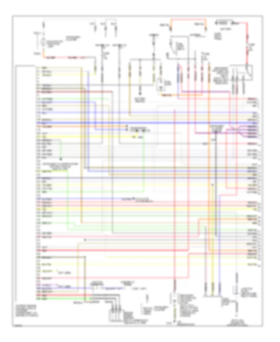
1.9L Turbo Diesel, Engine Performance Wiring Diagrams (2 of 2) for Volkswagen Jetta GL 1998
List of elements for 1.9L Turbo Diesel, Engine Performance Wiring Diagrams (2 of 2) for Volkswagen Jetta GL 1998:
- (above fuse/relay panel) j/b for on-board diagnostics
- Cold start injector
- Coolant system glow plug relay
- Coolant system glow plugs
- Cruise control system
- D/8
- Data link connector (behind center of dash)
- Diesel direct fuel injection (dfi) engine control module (ecm)
- Display unit control module
- E/2
- Egr vacuum regulator solenoid valve
- Engine glow plugs
- Fuel cut-off valve
- Fuel temper- ature sensor
- Fuse 50a
- Fuse/relay panel
- G1/12
- G2/5
- Glow plug ind
- Hot at all times
- Ignition
- Instrument cluster
- J/c (tv4) (above right of fuse/relay panel)
- J/c (tv5) (above right of fuse/relay panel)
- Modulating piston displacement sensor
- Nca
- Positive crankcase ventilation heating element
- Quantity adjuster
- Red
- T28/10
- T28/13
- T28/20
- Throttle position (tp) sensor/ closed throttle position (ctp) switch/kickdown switch (above accelerator pedal)
- U1/6
- U1/8
- U2/1
2.0L
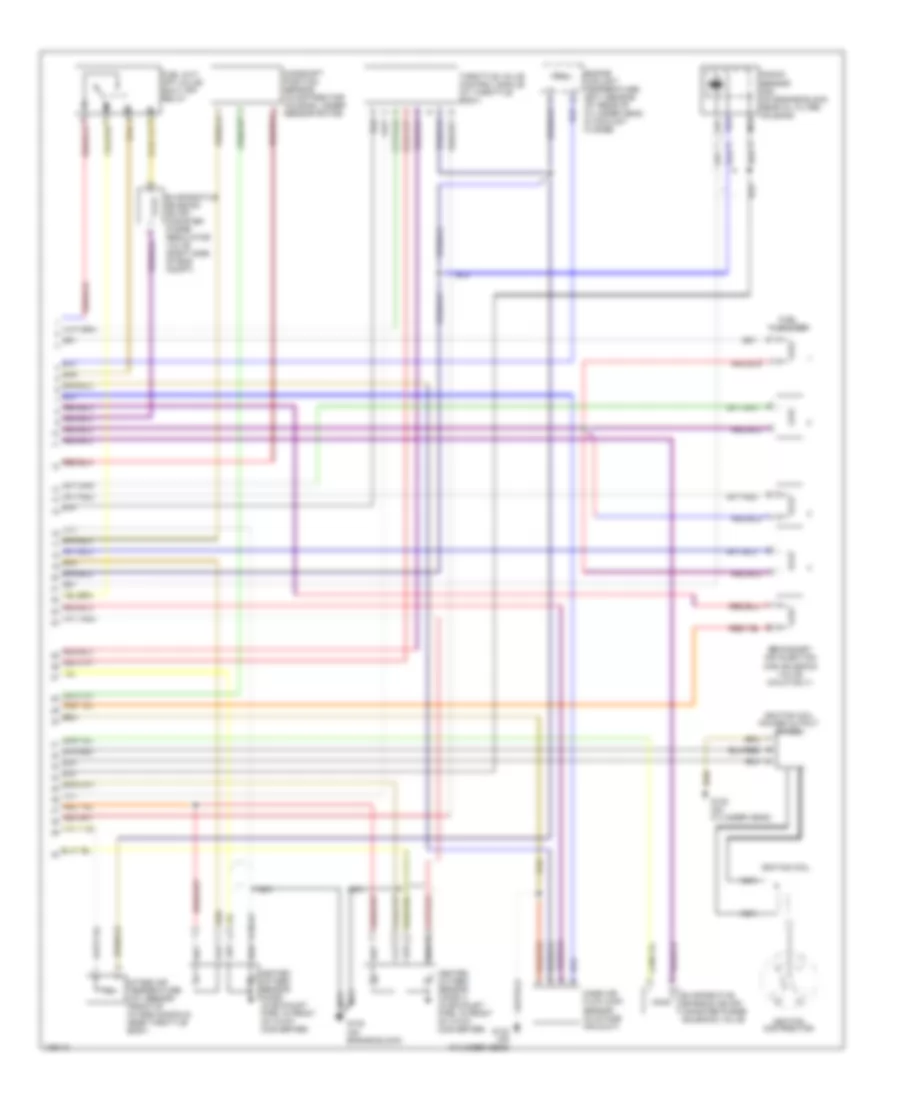
2.0L, Engine Performance Wiring Diagrams (1 of 2) for Volkswagen Jetta GL 1998
List of elements for 2.0L, Engine Performance Wiring Diagrams (1 of 2) for Volkswagen Jetta GL 1998:
- (not used)
- (on engine block)
- 30b
- A/c clutch cut-off relay
- Battery
- Battery ground
- D/8
- Data link connector (center of dash)
- E/2
- Engine speed sensor (on cylinder block behind oil filter)
- Fuel pump
- Fuel pump relay
- Fuse 10a
- Fuse 20a
- Fuse 30a
- Fuse/ relay panel
- Fuse/relay panel
- G1/3
- G1/4
- G1/6
- G1/8
- G1/9
- G132
- G2/4
- G2/8
- G2/9
- Ignition
- Ignition (15)
- Instrument cluster
- Instrument cluster system
- Instrument cluster system (control module/ display unit)
- Junction block (above fuse/ relay panel)
- Junction connector
- Leak detection pump
- M/1
- M/2
- Malfunction indicator lamp
- Motronic engine control module (in engine compartment, on center of plenum)
- Nca
- Red
- Secondary air injection (air) pump motor (calif. only) (below intake manifold, near thermostat housing)
- Secondary air injection (air) pump relay (calif. only) (behind left headlight)
- T28/13
- T28/20
- Transmission control module
- U1/9
- U2/1
- U2/2
- Vehicle speed signal
- W/1
- Z/2
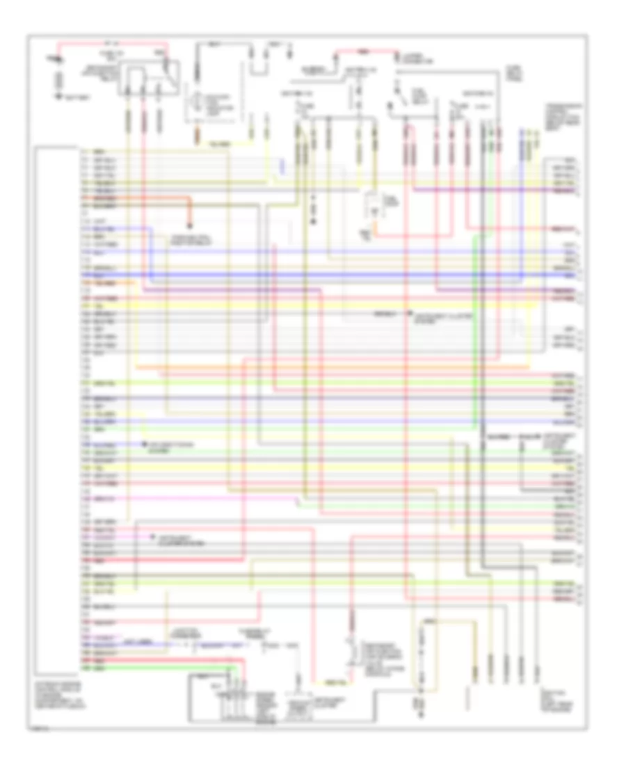
2.0L, Engine Performance Wiring Diagrams (2 of 2) for Volkswagen Jetta GL 1998
List of elements for 2.0L, Engine Performance Wiring Diagrams (2 of 2) for Volkswagen Jetta GL 1998:
- Camshaft position sensor (in distributor housing, under sensor rotor)
- Engine coolant temperature (ect) sensor (at rear of cylinder head, in coolant flange)
- Evaporative emission (evap) canister purge regulator valve (right side of eng compt)
- Evaporative emission (evap) canister purge solenoid valve
- Fuel cut- off valve/ shut off relay
- Fuel injectors
- G132 (on cylinder head)
- G132 (on engine block)
- Heated oxygen sensor (ho2s) (in exhaust pipe, in front of 3-way converter)
- Heated oxygen sensor (ho2s) 2 (in exhaust pipe, in front of 3-way converter)
- Ignition coil
- Ignition coil power output stage
- Ignition distributor
- Intake air temperature (iat) sensor (front of intake manifold, near throttle body)
- Knock sensor (ks) (on engine block, near oil filter housing)
- Mass air flow (maf) sensor (in intake air duct)
- Nca
- Secondary air injection (air) solenoid valve (calif only)
- Throttle valve control module (at throttle body)
2.8L
2.8L, Engine Performance Wiring Diagrams (1 of 2) for Volkswagen Jetta GL 1998
List of elements for 2.8L, Engine Performance Wiring Diagrams (1 of 2) for Volkswagen Jetta GL 1998:
- (not used)
- 30b
- Air conditioning system
- Battery
- D/8
- E/2
- Engine speed sensor (left side of engine)
- Fuel pump
- Fuel pump relay
- Fuse 10a
- Fuse 130 50a
- Fuse 20a
- Fuse/ relay panel
- Fuse/relay panel
- G1/3
- G1/4
- G1/6
- G1/8
- G1/9
- G2/4
- G2/8
- G2/9
- Ignition (15)
- Ignition coil (left rear of engine)
- Instrument cluster
- Instrument cluster system
- Jumper connector
- Junction connector
- M/1
- M/2
- Malfunc- tion indicator lamp
- Motronic engine control module (in engine compartment, on center of plenum)
- N/1
- Nca
- Park/neutral position relay
- Red
- Secondary air injection (air) solenoid valve (below intake manifold)
- Secondary air injection relay
- T28/13
- T28/20
- Transmission control module (tcm) (below rear seat)
- U1/9
- U2/1
- U2/2
- Vehicle speed output
- W/1
- Z/1
- Z/2
2.8L, Engine Performance Wiring Diagrams (2 of 2) for Volkswagen Jetta GL 1998
List of elements for 2.8L, Engine Performance Wiring Diagrams (2 of 2) for Volkswagen Jetta GL 1998:
- (at throttle body) throttle valve control module
- (in exhaust pipe, front of 3-way catalytic converter)
- Camshaft position sensor
- Data link connector (behind center of dash)
- Engine coolant temperature (ect) sensor (left rear of eng, on termostat housing)
- Evap canister purge regulator valve
- Evaporative emission canister purge regulator
- Fuel cut-off valve shut-off relay
- Fuel injectors
- Heated oxygen sensor (ho2s) 1 (in exhaust pipe, front of 3-way catalytic converter)
- Heated oxygen sensor (ho2s) 2
- Intake air temperature (iat) sensor (on rear of upper intake manifold)
- Junction block
- Knock sensor (ks) 1 (right side of cyl block)
- Knock sensor (ks) 2 (left side of cylinder block, above oil cooler housing)
- Leak detection pump
- Mass air flow (maf) sensor (in intake air duct, between air cleaner & throttle body)
- Nca
- Positive crankcase ventilation heating element
- Secondary air injection pump motor (below intake manifold, near thermostat housing)
- Solid state

 Čeština
 Dansk
Dansk Deutsch
 Ελληνικά
 English
 Español
 Suomi
Suomi Français
 Français
 עברית
עברית Hrvatski
 Magyar
 Italiano
 日本語
日本語 한국어
한국어 Nederlands
 Polski
 Português
 Português
 Română
 Русский
 Slovenčina
 Slovenščina
 Svenska
 Türkçe
 中文 (中国)