ENGINE PERFORMANCE
2.8L
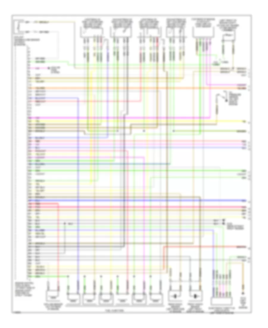
2.8L Turbo, Engine Performance Wiring Diagrams (1 of 3) for Volvo S80 T-6 2001
 https://portal-diagnostov.com/license.html
Automotive Electricians Portal FZCO
Automotive Electricians Portal FZCO
https://portal-diagnostov.com/license.html
https://portal-diagnostov.com/license.html
Automotive Electricians Portal FZCO
Automotive Electricians Portal FZCO
List of elements for 2.8L Turbo, Engine Performance Wiring Diagrams (1 of 3) for Volvo S80 T-6 2001:
- (downstream of left converter) heated oxygen sensor (ho2s) 4
- (downstream of right converter) heated oxygen sensor (ho2s) 2
- (left front of engine compt) intake air temper- ature sensor (turbo)
- (top rear of engine, in air duct) mass airflow (maf) sensor
- (upstream of left converter) heated oxygen sensor (ho2s) 3
- (upstream of right converter) heated oxygen sensor (ho2s) 1
- Coolant temperature sensor (on front of engine)
- Cooling fans system
- Electronic throttle module (etm) (left side of engine)
- Engine control module (ecm) (at right side of engine compt, forward of strut tower)
- Front knock sensor (left front side of engine)
- Fuel injectors
- G105 (rear of right front fender)
- G112 (left side of engine)
- Impulse sensor (on top rear of engine)
- Oil pressure sensor (on left side of engine)
- Pnk
- Rear knock sensor (left rear side of engine)
- Red
- Turbo
- W/o turbo
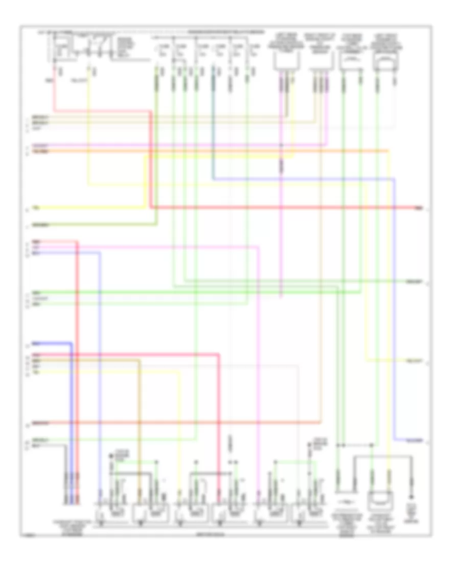
2.8L Turbo, Engine Performance Wiring Diagrams (2 of 3) for Volvo S80 T-6 2001
List of elements for 2.8L Turbo, Engine Performance Wiring Diagrams (2 of 3) for Volvo S80 T-6 2001:
- (left front corner of engine compt) canister purge (cp) valve
- (left rear of engine) intake manifold pressure sensor (turbo)
- (right front of engine compt) a/c pressure sensor
- (top of engine) g125
- (top rear of engine) turbo control valve (turbo)
- 15/20
- 15/23
- 15/24
- 15/25
- Air preheating ptc resistor (turbo) (top right side of engine)
- Camshaft adjustment valve (on top front of engine)
- Camshaft position (cmp) sensor (top rear of engine)
- Engine compartment relay/fuse box
- Engine control system main relay
- Fuse 10a
- Fuse 15a
- Fuse 20a
- Fuse 5a
- G112 (left side of engine)
- Hot at all times
- Ignition coils
- Pnk
- Red
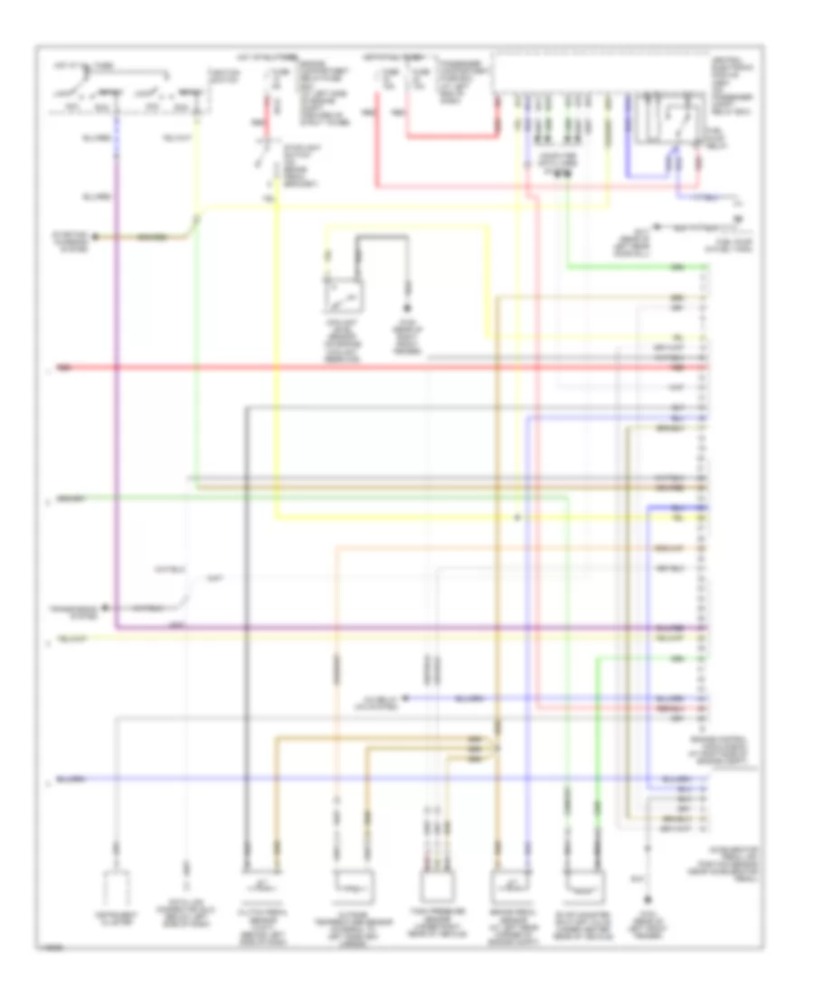
2.8L Turbo, Engine Performance Wiring Diagrams (3 of 3) for Volvo S80 T-6 2001
List of elements for 2.8L Turbo, Engine Performance Wiring Diagrams (3 of 3) for Volvo S80 T-6 2001:
- 15/24
- A/c relay (a/c system)
- A20
- Acc
- Accelerator pedal (ap) position sensor (near accelerator pedal)
- B14
- B17
- B18
- Brake pedal sensor (at left rear corner of engine compt)
- C14
- Central electronic module (cem) (on passenger compt relay box)
- Clutch pedal sensor (w/m/t) (behind left side of dash)
- Computer data lines system
- Coolant level sensor (on engine coolant resrvoir)
- Data link connector (dlc) (below left side of dash)
- Engine compartment relay/fuse box (at left side of engine compt, forward of strut tower)
- Engine control module (ecm) (at right side of engine compt)
- Evap canister shut-off valve (under center rear of vehicle)
- Fuel pump (in fuel tank)
- Fuel pump relay
- Fuse 10a
- Fuse 15a
- Fuse 5a
- G104 (rear of left front fender)
- G105 (rear of right front fender)
- G317 (rear of left rear door sill)
- Hot at all times
- Ignition switch
- Instrument cluster
- Lock
- Nca
- Outside temperature sensor (integral to left sideview mirror)
- Passenger compartment fuse box (at left end of dash)
- Red
- Run
- Start
- Starting/ charging system
- Stoplight switch (on brake pedal bracket)
- Tank pressure sensor (under right rear of vehicle)
- Transmission system
2.9L
2.9L, Engine Performance Wiring Diagrams (1 of 3) for Volvo S80 T-6 2001
List of elements for 2.9L, Engine Performance Wiring Diagrams (1 of 3) for Volvo S80 T-6 2001:
- (downstream of left converter) heated oxygen sensor (ho2s) 4
- (downstream of right converter) heated oxygen sensor (ho2s) 2
- (left front of engine compt) intake air temper- ature sensor (turbo)
- (top rear of engine, in air duct) mass airflow (maf) sensor
- (upstream of left converter) heated oxygen sensor (ho2s) 3
- (upstream of right converter) heated oxygen sensor (ho2s) 1
- Coolant temperature sensor (on front of engine)
- Cooling fans system
- Electronic throttle module (etm) (left side of engine)
- Engine control module (ecm) (at right side of engine compt, forward of strut tower)
- Front knock sensor (left front side of engine)
- Fuel injectors
- G105 (rear of right front fender)
- G112 (left side of engine)
- Impulse sensor (on top rear of engine)
- Oil pressure sensor (on left side of engine)
- Pnk
- Rear knock sensor (left rear side of engine)
- Red
- Turbo
- W/o turbo
2.9L, Engine Performance Wiring Diagrams (2 of 3) for Volvo S80 T-6 2001
List of elements for 2.9L, Engine Performance Wiring Diagrams (2 of 3) for Volvo S80 T-6 2001:
- (left front corner of engine compt) canister purge (cp) valve
- (left rear of engine) intake manifold pressure sensor (turbo)
- (right front of engine compt) a/c pressure sensor
- (top of engine) g125
- (top rear of engine) turbo control valve (turbo)
- 15/20
- 15/23
- 15/24
- 15/25
- Air preheating ptc resistor (turbo) (top right side of engine)
- Camshaft adjustment valve (on top front of engine)
- Camshaft position (cmp) sensor (top rear of engine)
- Engine compartment relay/fuse box
- Engine control system main relay
- Fuse 10a
- Fuse 15a
- Fuse 20a
- Fuse 5a
- G112 (left side of engine)
- Hot at all times
- Ignition coils
- Pnk
- Red
2.9L, Engine Performance Wiring Diagrams (3 of 3) for Volvo S80 T-6 2001
List of elements for 2.9L, Engine Performance Wiring Diagrams (3 of 3) for Volvo S80 T-6 2001:
- 15/24
- A/c relay (a/c system)
- A20
- Acc
- Accelerator pedal (ap) position sensor (near accelerator pedal)
- B14
- B17
- B18
- Brake pedal sensor (at left rear corner of engine compt)
- C14
- Central electronic module (cem) (on passenger compt relay box)
- Clutch pedal sensor (w/m/t) (behind left side of dash)
- Computer data lines system
- Coolant level sensor (on engine coolant resrvoir)
- Data link connector (dlc) (below left side of dash)
- Engine compartment relay/fuse box (at left side of engine compt, forward of strut tower)
- Engine control module (ecm) (at right side of engine compt)
- Evap canister shut-off valve (under center rear of vehicle)
- Fuel pump (in fuel tank)
- Fuel pump relay
- Fuse 10a
- Fuse 15a
- Fuse 5a
- G104 (rear of left front fender)
- G105 (rear of right front fender)
- G317 (rear of left rear door sill)
- Hot at all times
- Ignition switch
- Instrument cluster
- Lock
- Nca
- Outside temperature sensor (integral to left sideview mirror)
- Passenger compartment fuse box (at left end of dash)
- Red
- Run
- Start
- Starting/ charging system
- Stoplight switch (on brake pedal bracket)
- Tank pressure sensor (under right rear of vehicle)
- Transmission system

 Čeština
 Dansk
Dansk Deutsch
 Ελληνικά
 English
 Español
 Suomi
Suomi Français
 Français
 עברית
עברית Hrvatski
 Magyar
 Italiano
 日本語
日本語 한국어
한국어 Nederlands
 Polski
 Português
 Português
 Română
 Русский
 Slovenčina
 Slovenščina
 Svenska
 Türkçe
 中文 (中国)