GROUND DISTRIBUTION
Ground Distribution Wiring Diagram, Coupe (1 of 2) for Infiniti G35 2004
 https://portal-diagnostov.com/license.html
Automotive Electricians Portal FZCO
Automotive Electricians Portal FZCO
https://portal-diagnostov.com/license.html
https://portal-diagnostov.com/license.html
Automotive Electricians Portal FZCO
Automotive Electricians Portal FZCO
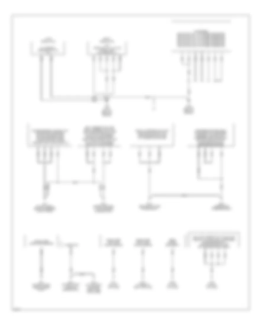
List of elements for Ground Distribution Wiring Diagram, Coupe (1 of 2) for Infiniti G35 2004:
- Camshaft position sensor (phase) (bank 1), crankshaft position sensor (pos), shield wire ((electric throttle control actuator) throttle position sensor 1) (for circuit from terminals: 1)), shield wire ((electric throttle control actuator) throttle position sensor 1 & 2) (for circuit from terminals: 2, 4 & 5)), shield wire ((electric throttle control actuator) throttle control motor) for circuit from terminals: 3 & 6)), camshaft position sensor (phase) (bank 2), park/neutral position switch (m/t), ecm (terminals: 1, 115 & 116), shield wire (knock sensor), passenger side vanity mirror lamp, auto anti-dezzling inside mirror (homelink universal transceiver), driver side vanity mirror lamp, sunroof motor assembly, map lamp, sunroof switch, passenger side door mirror (door mirror defogger), power window sub-switch (cpu & door lock & unlock switch)
- Data link connector (terminal: 5), driver side air mix door motor, display & a/c auto amp (terminal: 24), display unit (terminals: 22 & 24), power socket (floor console box) (a/t), navi control unit (terminals: 1 & 4), blower motor, glove box lamp, intake door motor, upper glove box lamp, power socket (right side instrument panel), passenger side air mix door motor, mode door motor
- Display & a/c auto lamp (terminal: 14), ipdm e/r (terminal: 38 & 60), ipdm e/r (terminal: 50), horn (low), horn (high), right front combination lamp (terminal: 8) headlamp (high) & fog), cooling fan motor 1, left front side marker lamp, left front combination lamp (terminal: 4) (headlamp low,turn signal/parking & parking), brake fluid level switch, front wiper motor, cooling fan motor 2, vdc/tcs/abs control unit (terminals: 28 & 29)
- E17 (on right side of engine compt)
- E43 (on left front side of engine compt)
- Fuel level sensor unit & fuel pump (terminal: 5) (fuel level sensor (main) & fuel tank temperature sensor), driver side door mirror (door mirror defogger), power window main switch (cpu, power window lock switch, door lock & unlock switch & illumination), driver side door lock assembly (door key cylinder switch), a/t pv ign relay (early production)
- Fuse block (j/b), (terminal: 7b) (accessory relay & blower relay), illumination control switch, data link connector (terminal: 4), vdc off switch, combination meter (terminals: 45, 46 & 47), steering angle sensor, door mirror remote control switch, combination switch, clock, navi switch, a/c & audio controller, cigarette lighter socket, hazard switch, a/t device (terminal: 1) (shift lock solenoid & park position switch), a/t device (terminal: 9) (mode select switch), ashtray illumination, passenger side heated seat switch, bcm, driver side heated seat switch, air bag diagnosis sensor unit, compass, trunk lid opener switch, heated seat relay
- Ipdm e/r (terminal: 14), daytime light relay 1, daytime light relay 2, hood switch, right front combination lamp (terminal: 4) (headlamp low, turn signal/parking & parking), daytime light control unit, right front side marker lamp, washer level sensor, left front combination lamp (terminal: 8) (headlamp high & foglamp) (usa only), ipdm e/r (terminal: 50) (m/t) (early production)
- M30 (behind instrument cluster)
- M66 (behind right side of dash)
Ground Distribution Wiring Diagram, Coupe (2 of 2) for Infiniti G35 2004
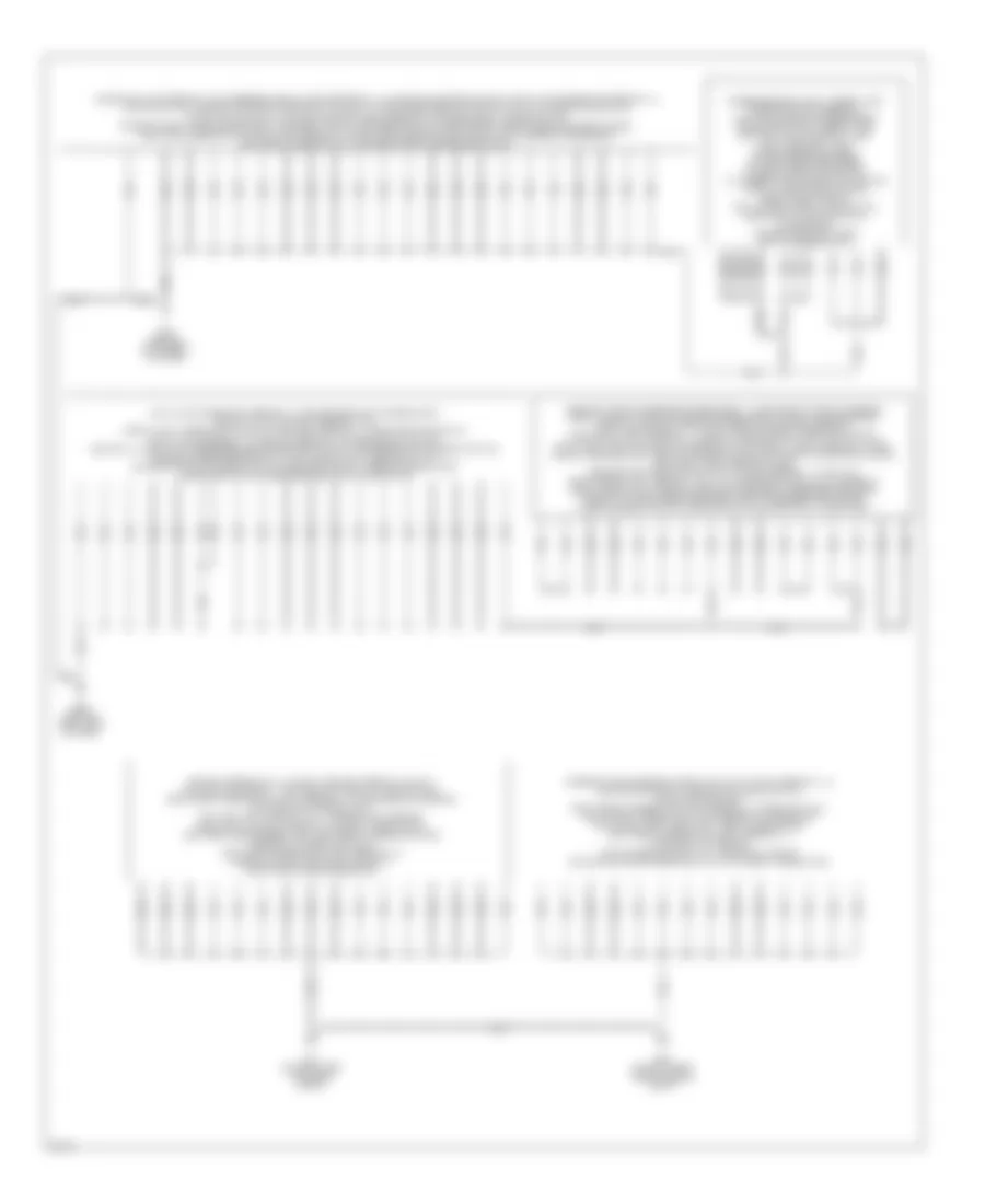
List of elements for Ground Distribution Wiring Diagram, Coupe (2 of 2) for Infiniti G35 2004:
- (early production)
- (late production)
- A/t
- A/t assembly (terminals: 5 & 10) (a/t)
- Alternator (e)
- B103 (under trim panel, at left rear of luggage compt)
- B18 (on left "b" pillar)
- B29 (on left "c" pillar)
- B402 (under front passenger seat)
- B407 (at base of right "b" pillar)
- B413 (behind right side of rear seat)
- B452 (at left "c" pillar)
- B5 (on left front side of passenger compt floor)
- Condenser, ignition coil no. 1 (w/ power transistor), ignition coil no. 2 (w/ power transistor), ignition coil no. 3 (w/ power transistor), ignition coil no. 4 (w/ power transistor), ignition coil no. 5 (w/ power transistor), ignition coil no. 6 (w/ power transistor)
- Driver side seat control unit, driver side power seat switch (sliding switch), driver side front seat cushion heater, driver side seat belt buckle switch
- E212 (on right front corner of engine compt)
- E213 (on top front of engine, near timing chain case)
- E22 (on right front side of engine compt)
- F22 (a/t) (on top front of engine)
- F23 (on top front of engine)
- Fuel level sensor unit & fuel pump (terminal: 3) (fuel pump), condenser, bose speaker amp, high-mounted stop lamp (on the rear parcel shelf)
- Left license plate lamp, right license plate lamp, left rear combination lamp (tail & stop, turn signal, back-up & side marker), right rear combination lamp (tail & stop, turn signal, back-up & side marker)
- Passenger side seat belt buckle switch, passenger side seat control unit, passenger side power seat switch (sliding switch), passenger side front seat cushion heater
- Rear window defogger (-)
- Shield wire (crash zone sensor)
- Shield wire (left side air bag sensor)
- Shield wire (right side air bag sensor)
- Tcm (terminals: 5, 14, 24 & 46) shield wire (tcm (terminal: 5))
- Trunk lid opener actuator, trunk room lamp switch, high-mounted stop lamp (in the rear air spoiler)
Ground Distribution Wiring Diagram, Sedan (1 of 2) for Infiniti G35 2004
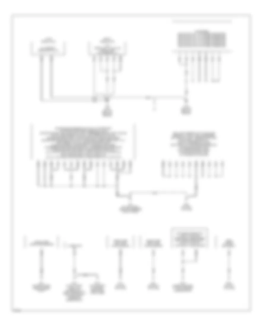
List of elements for Ground Distribution Wiring Diagram, Sedan (1 of 2) for Infiniti G35 2004:
- Camshaft position sensor (phase) (bank 1), crankshaft position sensor (pos), camshaft position sensor (phase) (bank 2), shield wire (electric throttle control actuator (throttle position sensor 1) (for circuit from terminal: 1), shield wire (electric throttle control actuator (throttle position sensor 1&2) (for circuit from terminals: 2,4&5), shield wire (electric throttle control actuator (throttle control motor) (for circuit from terminals: 3&6), park/neutral position switch (m/t), ecm (terminal: 1,115 & 116), awd control unit (terminal: 10 & 11) (late production), a/t pv ign relay (early production), shield wire (knock sensor), passenger side door mirror (w/ door mirror defogger), front passenger side power window sub-switch (cpu, door lock & unlock switch, illumination)
- Data link connector (terminal: 5), driver side air mix door motor, display & a/c auto amp (terminal: 24), display unit (terminals: 22 & 24), a/t device (terminal: 1) (park position switch, shift lock solenoid), a/t device (terminal: 9) (mode select switch), ashtray illumination, passenger side heated seat switch, driver side heated seat switch, air bag diagnosis sensor unit, navi control unit (terminals: 1 & 4), blower motor, glove box lamp, intake door motor, upper glove box lamp, mode door motor, passenger side air mix door motor
- E17 (on right side of engine compt)
- E43 (on left front side of engine compt)
- Fuse block (j/b) (terminal: 7b, accessory relay & blower relay), illumination control switch, data link connector (terminal: 4), vdc off switch, combination meter (terminals: 45, 46 & 47), door mirror remote control switch, combination switch, clock, navi switch, a/c & audio controller, cigarette lighter socket, hazard switch, power socket (floor console box), compass, trunk lid opener switch, power socket (right side instrument panel), fuel level sensor unit & fuel pump (terminal: 5) (fuel level sensor (main) & fuel tank temperature sensor), bcm, snow mode switch (late production), heated seat relay
- Ipdm e/r (terminals: 14, 38 & 50), ipdm e/r (terminal: 54) (a/t), daytime light relay 1, daytime light relay 2, hood switch, right front combination lamp (terminal: 4) (turn signal & parking), daytime light control unit, daytime light control unit, washer level sensor, horn (high), ipdm e/r (terminal: 60) (early production), left front side marker lamp, left front combination lamp (terminal: 5) (headlamp low), left front combination lamp (terminal: 8) (headlamp high & foglamp) (usa only), right front side marker lamp
- M30 (behind instrument cluster)
- M66 (behind right side of dash)
- Passenger side vanity mirror lamp, sunroof motor assembly, auto anti-dazzling inside mirror, driver side vanity mirror lamp, map lamp, left personal lamp, right personal lamp, driver side door mirror (w/ door mirror defogger), power window main switch (w/ interruption detection function for all door window or for front door window) (cpu, power window lock switch, door lock & unlock switch, illumination), driver side front door key cylinder switch
- Steering angle sensor, display & a/c auto amp (terminal: 14), cooling fan motor 1, brake fluid level switch, cooling fan motor 2, right front combination lamp (terminal: 5) (headlamp low), right front combination lamp (terminal: 8) (headlamp high & fog lamp), horn (low), front wiper motor, left front combination lamp (terminal: 4) (turn signal & parking), vdc/tcs/abs control unit (terminals: 28 & 29), cooling fan motor (terminals: 3 & 4) (a/t) (early production),
Ground Distribution Wiring Diagram, Sedan (2 of 2) for Infiniti G35 2004
List of elements for Ground Distribution Wiring Diagram, Sedan (2 of 2) for Infiniti G35 2004:
- (early production)
- (late production)
- A/t
- A/t assembly (terminals: 5 & 10)
- Alternator (e)
- B103 (under trim panel, at left rear of luggage compt)
- B18 (on left "b" pillar)
- B24 (on right "b" pillar)
- B242 (on left "c" pillar)
- B29 (on left "c" pillar)
- B5 (on left front side of passenger compt floor)
- Condenser, ignition coil no. 1 (w/ power transistor), ignition coil no. 2 (w/ power transistor), ignition coil no. 3 (w/ power transistor), ignition coil no. 4 (w/ power transistor), ignition coil no. 5 (w/ power transistor), ignition coil no. 6 (w/ power transistor)
- Driver side power seat switch (w/ power seat w/o driver positioner) (terminals: 2 & 8), driver side seat belt buckle switch, passenger side seat belt buckle switch, driver seat control unit (terminals: 16 & 33), driver side front seat cushion heater (w/ drive positioner), driver side power seat switch (w/ drive positioner) (terminals: 1 & 7), seat memory switch, driver side front seat cushion heater (w/ power seat, w/o drive positioner), passenger side power seat switch, passenger side front seat cushion heater, left rear power window sub-switch (cpu (w/ anti-pinch system for all door window) & illumination), right rear power window sub-switch (cpu (w/ anti-pinch system for all door window) & illumination)
- E212 (awd: at right front of engine compt) (early production: on right front corner of engine compt)
- E213 (on top front of engine, near timing chain case)
- E22 (on right front side of engine compt)
- F22 (a/t) (on top front of engine)
- F23 (on top front of engine)
- Fuel level sensor unit & fuel pump (terminal: 3) (fuel lamp), condenser, left back-up lamp, license plate lamp, trunk room lamp switch, trunk lid opener actuator, right back-up lamp, bose speaker amp, high-mounted stop lamp (on the rear parcel shelf), high-mounted stop lamp (in the rear air spoiler)
- Left rear combination lamp (tail & stop, turn signal, side marker), right rear combination lamp (tail & stop, turn signal, side marker)
- Rear window defogger (-)
- Shield wire (crash zone sensor)
- Shield wire (left side air bag sensor)
- Shield wire (right side air bag sensor)
- Tcm (terminals: 5,14,24 & 46), shield wire (tcm (terminal: 5))

 Čeština
 Dansk
Dansk Deutsch
 Ελληνικά
 English
 Español
 Suomi
Suomi Français
 Français
 עברית
עברית Hrvatski
 Magyar
 Italiano
 日本語
日本語 한국어
한국어 Nederlands
 Polski
 Português
 Português
 Română
 Русский
 Slovenčina
 Slovenščina
 Svenska
 Türkçe
 中文 (中国)