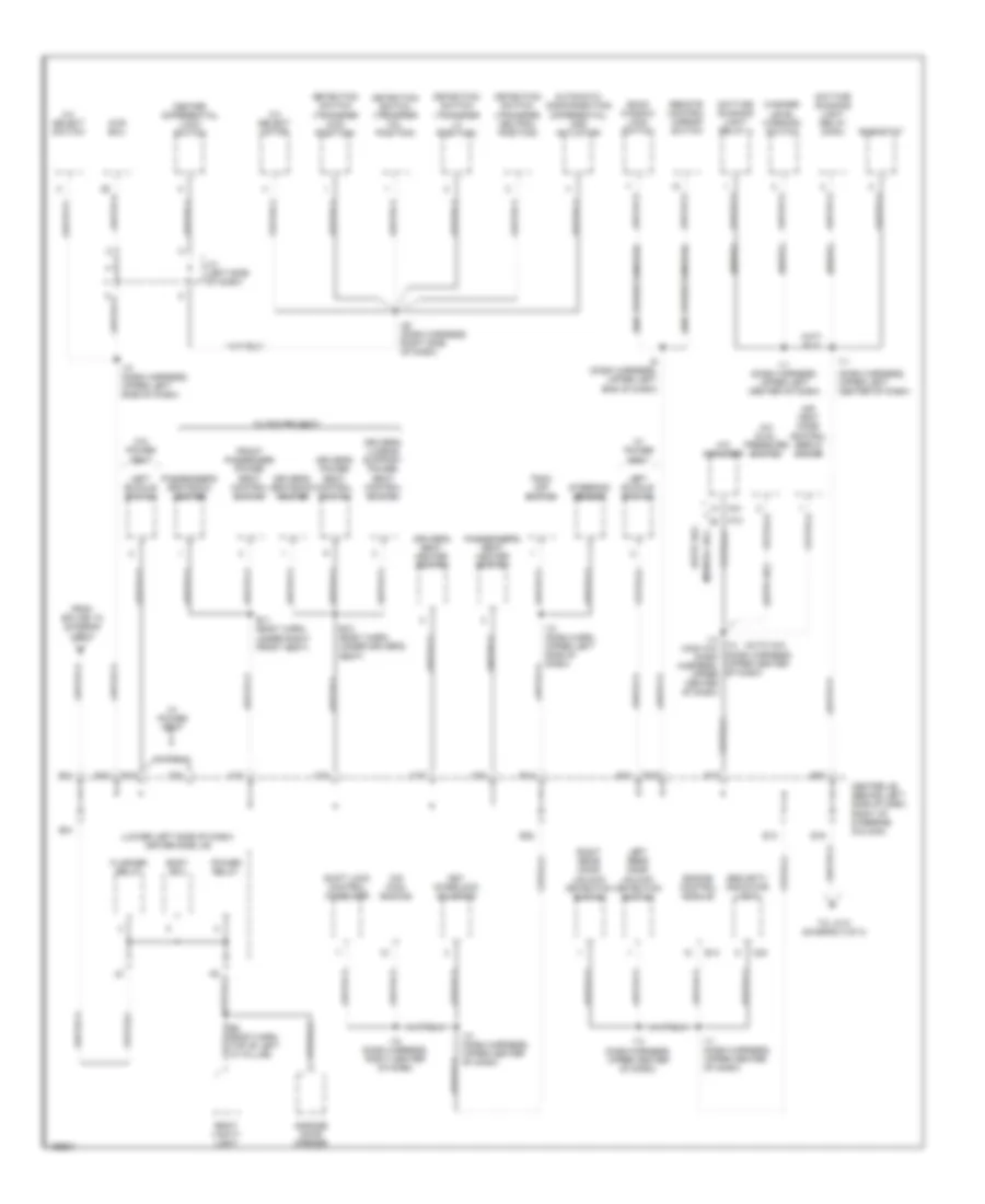
GROUND DISTRIBUTION
Ground Distribution Wiring Diagram (1 of 3) for Toyota 4Runner Limited 2002
 https://portal-diagnostov.com/license.html
Automotive Electricians Portal FZCO
Automotive Electricians Portal FZCO
https://portal-diagnostov.com/license.html
https://portal-diagnostov.com/license.html
Automotive Electricians Portal FZCO
Automotive Electricians Portal FZCO
List of elements for Ground Distribution Wiring Diagram (1 of 3) for Toyota 4Runner Limited 2002:
- (left side of engine compt, on inner fender panel) engine room r/b
- (w/ moon roof) personal light
- B1 (body harness, inside left front door)
- B3 (body harness, center of windshield header)
- Bj (right rear side of luggage compt)
- Brake fluid level warning switch
- C21
- C23
- C27
- Center air bag sensor assembly
- Cigarette lighter
- Clock
- Combination meter
- Combination switch
- D22
- E2 (eng compt harn, left front of engine compt)
- Ea (front of right front fender)
- Eb (front of left front fender)
- Efi relay
- Engine
- Glove box light
- Heater relay
- Hood courtesy switch
- I13 (dash harness, upper center of dash)
- Ie (left side of dash)
- Ig (right kick panel)
- J/c 1 & 2 (left inner fender panel, front of strut tower)
- J/c 4 (left side of dash)
- J1 a
- Left front door key lock & unlock switch
- Left front door lock control switch
- Left front door unlock detection switch
- Left front fog- light
- Left front parking light
- Left front power outlet
- Left front turn signal light
- Left mirror heater
- Moon roof control motor & limit switch
- Moon roof control relay & switch
- Power outlet relay
- Power window master switch
- Rear power outlet
- Rear window defogger switch
- Right front buckle switch
- Right front fog- light
- Right front parking light
- Right front power outlet
- Right front turn signal light
- Starter relay
- To center j/b pin e11 (diagram 2 of 3)
- To data link connector 3 (diagram 3 of 3)
- To junction connector 9 (diagram 3 of 3)
- To splice b8 (diagram 3 of 3)
- Unlock warning switch
- V10
- V11
- V16
- V19
- Vsc actuator
- Vsc ecu
- W/ anti-theft
- W/ power windows
- W/o power windows
Ground Distribution Wiring Diagram (2 of 3) for Toyota 4Runner Limited 2002
List of elements for Ground Distribution Wiring Diagram (2 of 3) for Toyota 4Runner Limited 2002:
- (auto a/c)
- (dash harness, upper left center of dash)
- (lower left side of dash) driver side j/b
- (manual a/c)
- (w/drl)
- (w/o power window)
- 2-4 select motor
- 2-4 select switch
- 4wd ecu
- A/c amplifier
- A/c dual pressure switch
- A12
- A31
- Air vent mode control servo motor
- Automatic disconnecting differential add actuator
- B10 (body harn, under driver's seat)
- B11 (body harn, under right front seat)
- B2 (body harn, top of left "a" pillar)
- Back window lock switch
- Body ecu
- C15
- C18
- C19
- C20
- C22
- C24
- Center differential lock switch
- Center j/b (behind left side of dash, right of steering column)
- Daytime running light relay (main)
- Daytime running light relay 4
- Detection switch (transfer 4wd position)
- Detection switch (transfer h4l position)
- Detection switch (transfer l4 position)
- Detection switch (transfer neutral position)
- Driver's lumbar support power seat control switch
- Driver's power seat control switch
- Driver's seat heater switch
- Driver's seatback heater
- E11
- E12
- E13
- E14
- E15
- E16
- E17
- E18
- E19
- E20
- E21
- E22
- Engine control module
- Flasher relay
- From splice i10 (diagram 1 of 3)
- Front passenger power seat control switch
- Garage door opener
- I10 (dash harn, upper left side of dash)
- I10 (dash harness, upper left side of dash)
- I11
- I11 (dash harness, upper center of dash)
- I11 (dash harness, upper left center of dash)
- I12 (dash harness, upper center of dash)
- I13 (dash harness, upper center of dash)
- I14 (man a/c) (dash harness, upper center of dash)
- I18 (dash harness, right center of dash)
- I20 (dash harness, right side of dash)
- I6 (dash harness, upper left end of dash)
- J/3 (left side of dash)
- Key interlock solenoid
- Left buckle switch
- Left rear door unlock detection switch
- O/d main switch
- Passenger's seat heater switch
- Passenger's seatback heater
- Power relay
- Remote control mirror switch
- Rheostat
- Right rear door unlock detection switch
- Right vanity light
- Security indicator light
- Shift lock control computer
- Steering sensor
- To j/c 9 (diagram 3 0f 3)
- Trac off switch
- W/ power seat
- W/0 power seat
- Washer level warning switch
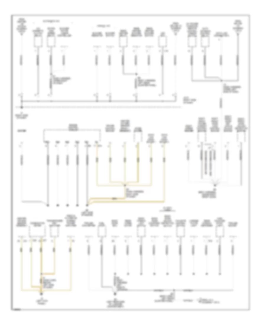
Ground Distribution Wiring Diagram (3 of 3) for Toyota 4Runner Limited 2002
List of elements for Ground Distribution Wiring Diagram (3 of 3) for Toyota 4Runner Limited 2002:
- (w/ power windows)
- (w/ power windows) remote control mirror switch
- (w/o power windows)
- A/c magnetic clutch relay
- Auto antenna control relay
- Automatic a/c
- B5 (body harness, inside right front door)
- B6 (body harness, left rear quarter panel)
- B8 (body harn, left rear quarter panel)
- B9 (body harness, left side of liftgate)
- Back door courtesy switch
- Back door ecu
- Back door unlock detection switch
- Back window limit switch
- Bh (left rear side of luggage compartment)
- Blower motor linear controller
- Blower resistor
- Blower switch
- C21
- C25
- C27
- Center air bag sensor assembly
- Combination meter
- Cruise control switch
- Data link conn- ector 1
- Data link conn- ector 3
- Data link connector 3
- E01
- E02
- E03
- E04
- E10
- Ec (left side of engine)
- Engine control module
- Extra high speed relay
- From center j/b pin e16 (diagram 2 of 3)
- From j/c 4 (diagram 1 of 3)
- From splice i10 (diagram 1 of 3)
- From splice i13 (diagram 1 of 3)
- Fuel pump
- Heated oxygen sensor (bank 1, sensor 2)
- High mounted stop- light
- I10 (dash harness, upper left side of dash)
- I20 (dash harness, right side of dash)
- I21 (dash harness, upper right of dash)
- I9 (dash harn, behind left side of dash)
- Id (left kick panel)
- If (right side of dash)
- Igniter
- J/c 9 (right side of dash)
- License plate light
- Manual a/c
- Me01
- Noise filter
- R18
- Radio & player or stereo power amplifier
- Rear heater blower resistor
- Rear heater blower switch
- Rear heater relay
- Rear window defogger
- Rear wiper motor
- Right front door key lock & unlock switch
- Right front door lock control switch
- Right front door unlock detection switch
- Right front power window control switch
- Right mirror heater
- Tailgate control switch
- Trailer converter
- Trailer socket
- Transponder key amplifier
- V19
- Vsc ecu
- W/ anti- theft

 Čeština
 Dansk
Dansk Deutsch
 Ελληνικά
 English
 English
 Español
 Suomi
Suomi Français
 עברית
עברית Hrvatski
 Magyar
 Italiano
 日本語
日本語 한국어
한국어 Nederlands
 Polski
 Português
 Português
 Română
 Русский
 Slovenčina
 Slovenščina
 Svenska
 Türkçe
 中文 (中国)