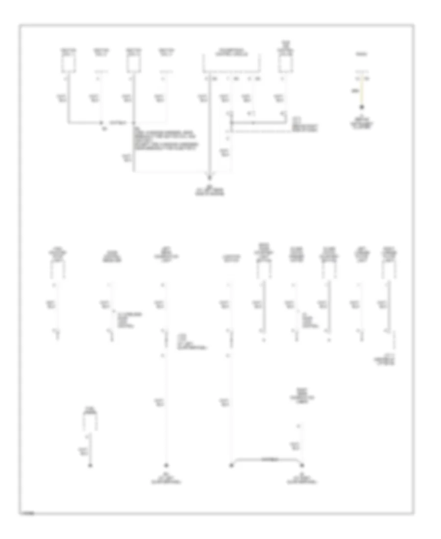
GROUND DISTRIBUTION
Ground Distribution Wiring Diagram (1 of 4) for Toyota Matrix 2003
 https://portal-diagnostov.com/license.html
Automotive Electricians Portal FZCO
Automotive Electricians Portal FZCO
https://portal-diagnostov.com/license.html
https://portal-diagnostov.com/license.html
Automotive Electricians Portal FZCO
Automotive Electricians Portal FZCO
List of elements for Ground Distribution Wiring Diagram (1 of 4) for Toyota Matrix 2003:
- (2wd)
- (4wd)
- (ex xrs)
- (except xrs)
- (w/o abs) combination meter
- (xrs)
- Braided wire
- Brake fluid level warning switch
- Camshaft position sensor shield
- Canada
- Combination meter
- Crankshaft position sensor shield
- Data link connector
- Daytime running light relay
- E1 (in engine room main harness, near breakout for skid control ecu)
- E4 (in engine room main harness, near engine room j/b)
- Ea (at front side of right fender)
- Eb (on left front suspension tower)
- Ec (at left rear side of cylinder head)
- Ec (at left rear side of engine)
- Efi relay
- Engine room r/b
- Except xrs
- Fan 2 relay
- Fan resistor
- Front wiper motor
- Heated oxygen sensor (bank 1 sensor 1)
- Heated oxygen sensor (bank 1 sensor 2)
- Heated oxygen sensor shield bank 1 sensor 1
- Heated oxygen sensor shield bank 1 sensor 2
- I13 (in engine harness, behind right side of dash, near pass-through grommet)
- J/c 3, j/c 4 (behind right side of dash)
- J/c 5, j/c 6 (behind right side of dash)
- Knock sensor shield
- Left front fog lamp
- Left front parking/ turn signal lamp
- Left headlight (high)
- Powertrain control module
- Pressure switch
- Red
- Right front fog lamp
- Right front parking/ turn signal lamp
- Right headlight (high)
- Skid control ecu w/ actuator
- Vehicle speed sensor w/o abs)
- Washer level switch
- Xrs
Ground Distribution Wiring Diagram (2 of 4) for Toyota Matrix 2003
List of elements for Ground Distribution Wiring Diagram (2 of 4) for Toyota Matrix 2003:
- Back door courtesy light switch
- Bh (at left quarterpanel)
- Bi (at right quarterpanel)
- Door control receiver
- E2 (xrs: in engine harness, near breakout for ignition coil and ignitor 3 except xrs: in engine hardness, near breakout for injector 3)
- Ed (at left rear side of engine)
- Fuel pump
- Glass hatch courtesy switch
- Glass hatch opener motor
- High mounted stop light
- Idle air control valve
- If (behind instrument cluster)
- Ignition coil 1
- Ignition coil 2
- Ignition coil 3
- Ignition coil 4
- J/c 11 (center of liftgate)
- J/c 3, j/c 4 (behind right side of dash)
- J/c 8, j/c 9 (at left quarterpanel)
- Junction switch
- Left license plate light
- Left rear combination light
- Powertrain control module
- Radio
- Right license plate light
- Right rear combination light
- W/ door lock control
- W/ wireless door lock control
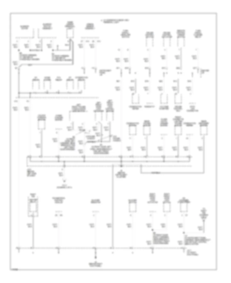
Ground Distribution Wiring Diagram (3 of 4) for Toyota Matrix 2003
List of elements for Ground Distribution Wiring Diagram (3 of 4) for Toyota Matrix 2003:
- A13
- Airbag sensor assembly
- B1 (in front door left harn, near breakout for left front door speaker)
- B11
- B12
- B13
- B14
- B15
- B16
- B17
- B18
- B19
- B2 (in front door left harness, near breakout for left front door speaker)
- B20
- B21
- B22
- B4 (in roof harness, at center of windshield header)
- B5 (in roof harness, at center of windshield header)
- Blower resistor
- Blower switch
- Cd changer (if equipped)
- Center j/b
- Combination meter
- Combination switch
- Cruise control actuator
- Cruise control ecu
- Cruise control switch
- Data link connector
- Door speaker)
- Front cigarette lighter/ power outlet
- Glass hatch opener switch
- H10
- Heater relay
- I10
- I10 (in instrument panel harness, near breakout for air inlet control servo motor)
- Ie (behind instrument cluster)
- Ig (behind right kick panel)
- Ig1 relay
- Inner mirror personal light
- Instrument panel j/b
- Integration relay
- J/c 2 (behind left side of dash)
- J/c 7 (at right kick panel)
- Left front door lock actuator
- Left front door lock control switch
- Left front power window/door lock switch
- Noise filter
- P/w relay
- Personal light
- Powertrain control module
- Rear defogger switch
- Rear power outlet
- Remote control mirror switch
- Rheostat
- Right front door lock actuator
- Right front door lock switch
- Right r/b
- St relay
- Sunroof motor
- Sunroof switch assembly
- To i7 (diagram 4 of 4)
- To right r/b (diagram 4 of 4)
- Turn signal flasher relay
- Turn signal/ headlamp switch
- Unlock warning switch
- Voltage inverter
- W/ moonroof & rear view a
- W/o power window
- W/power window
- Wiper/ washer switch
Ground Distribution Wiring Diagram (4 of 4) for Toyota Matrix 2003
List of elements for Ground Distribution Wiring Diagram (4 of 4) for Toyota Matrix 2003:
- A/c switch
- A/c/ fresh/ recirculation switch illumination
- A/t shift lever illumination
- A11
- A12
- A13
- A14
- A15
- A16
- A17
- A19
- A20
- A21
- A22
- Abs deceleration sensor
- Blower motor switch illumination
- Defogger switch illumination
- From i10 (diagram 3 of 4)
- From j/c 2 (diagram 3 of 4)
- Front cigar lighter illumination
- Glass breakage sensor ecu
- Hazard switch
- Hazard switch illumination
- I10 (in instrument panel harness, near breakout for air inlet control servo motor)
- I7 (in instrument panel harness, near breakout for power outlet) (115v)
- Inv relay
- Left buckle switch
- Main switch
- Main switch illumination
- O/d main switch
- P-point relay
- Radio illumination
- Right buckle switch
- Right j/b
- Right r/b
- Security indicator
- Shift lock control ecu
- Tvip ecu

 Čeština
 Dansk
Dansk Deutsch
 Ελληνικά
 English
 Español
 Suomi
Suomi Français
 Français
 עברית
עברית Hrvatski
 Magyar
 Italiano
 日本語
日本語 한국어
한국어 Nederlands
 Polski
 Português
 Português
 Română
 Русский
 Slovenčina
 Slovenščina
 Svenska
 Türkçe
 中文 (中国)