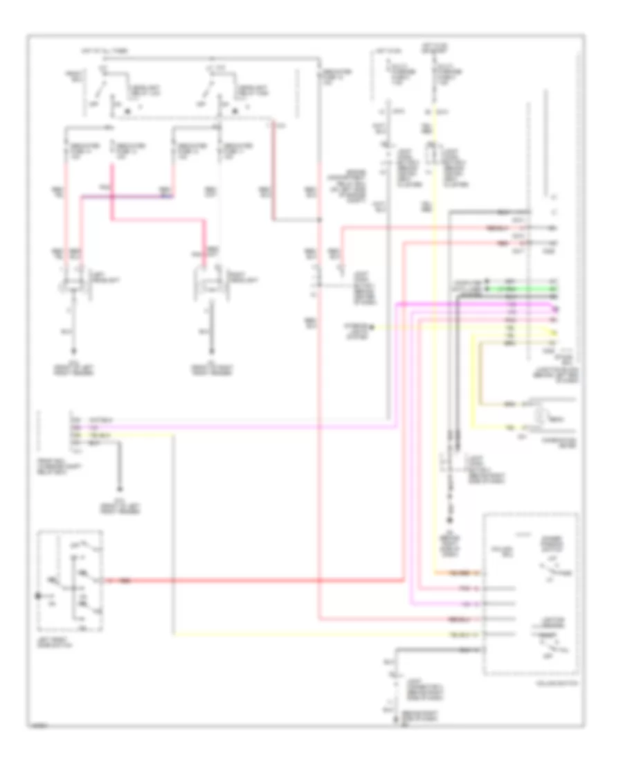
HEADLIGHTS
Headlight Wiring Diagram for Mitsubishi Lancer LS 2002
List of elements for Headlight Wiring Diagram for Mitsubishi Lancer LS 2002:
- (behind right side of dash) g3
- A10
- A11
- Beam
- C01
- C210
- C214
- C217
- C226
- C228
- Column switch
- Column- ecu
- Combination meter
- Computer data lines system
- Dedicated fuse 11 10a
- Dedicated fuse 12 10a
- Dedicated fuse 13 10a
- Dedicated fuse 14 10a
- Dedicated fuse 18 10a
- Dimmer/ passing switch
- Engine compartment relay box (on left side of engine compt)
- Etacs ecu
- Front ecu
- Front ecu (in engine compt relay box)
- G1 (front of right front fender)
- G13 (front of left front fender)
- G3 (behind right side of dash)
- Head
- Headlight relay high
- Headlight relay low
- Hot at all times
- Hot in on
- Hot in on or start
- Interior lights system
- Joint conn- ector 1 (behind center of dash)
- Joint conn- ector 2 (behind instru- ment cluster)
- Joint conn- ector 3 (behind right side of dash)
- Joint conn- ector 5 (behind instru- ment cluster)
- Joint connector 3 (behind right side of dash)
- Junction block (behind left end of dash)
- Left front door switch
- Left headlight
- Lighting switch
- Multi- purpose fuse 2 7.5a
- Multi- purpose fuse 5 7.5a
- Off
- Pass
- Pnk
- Red
- Right headlight
- Tail
 Čeština
 Dansk
Dansk Deutsch
 Ελληνικά
 English
 Español
 Suomi
Suomi Français
 Français
 עברית
עברית Hrvatski
 Magyar
 Italiano
 日本語
日本語 한국어
한국어 Nederlands
 Polski
 Português
 Português
 Română
 Русский
 Slovenčina
 Slovenščina
 Svenska
 Türkçe
 中文 (中国)
 English