
 Čeština
 Dansk
Dansk Deutsch
 Ελληνικά
 English
 English
 Español
 Suomi
Suomi Français
 Français
 עברית
עברית Magyar
 Italiano
 日本語
日本語 한국어
한국어 Nederlands
 Polski
 Português
 Português
 Română
 Русский
 Slovenčina
 Slovenščina
 Svenska
 Türkçe
 中文 (中国)

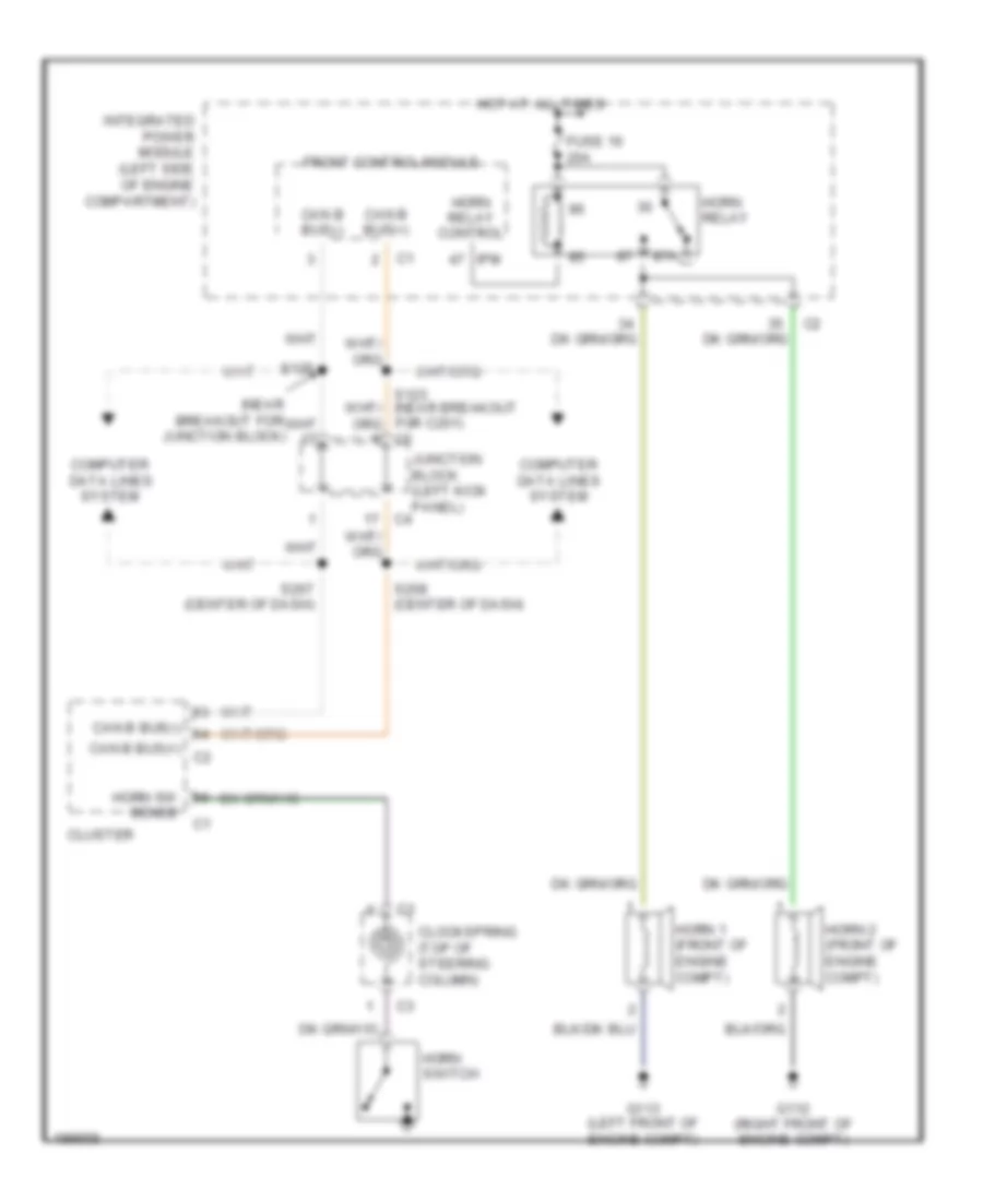
HORN
Horn Wiring Diagram for Dodge Durango 2005
List of elements for Horn Wiring Diagram for Dodge Durango 2005:

ANTI-LOCK BRAKESAIR CONDITIONINGCRUISE CONTROLBODY CONTROL MODULESANTI-THEFTCOMPUTER DATA LINESENGINE PERFORMANCECOOLING FANGROUND DISTRIBUTIONDEFOGGERSEXTERIOR LIGHTSHEADLIGHTSMEMORY SYSTEMSHORNINTERIOR LIGHTSINSTRUMENT CLUSTERPOWER MIRRORSPOWER WINDOWSPOWER DOOR LOCKSPOWER DISTRIBUTIONRADIOSHIFT INTERLOCKPOWER TOP/SUNROOFPOWER SEATSSTARTING/CHARGINGTRANSMISSIONSUPPLEMENTAL RESTRAINTSWARNING SYSTEMSWIPER/WASHER