HORN
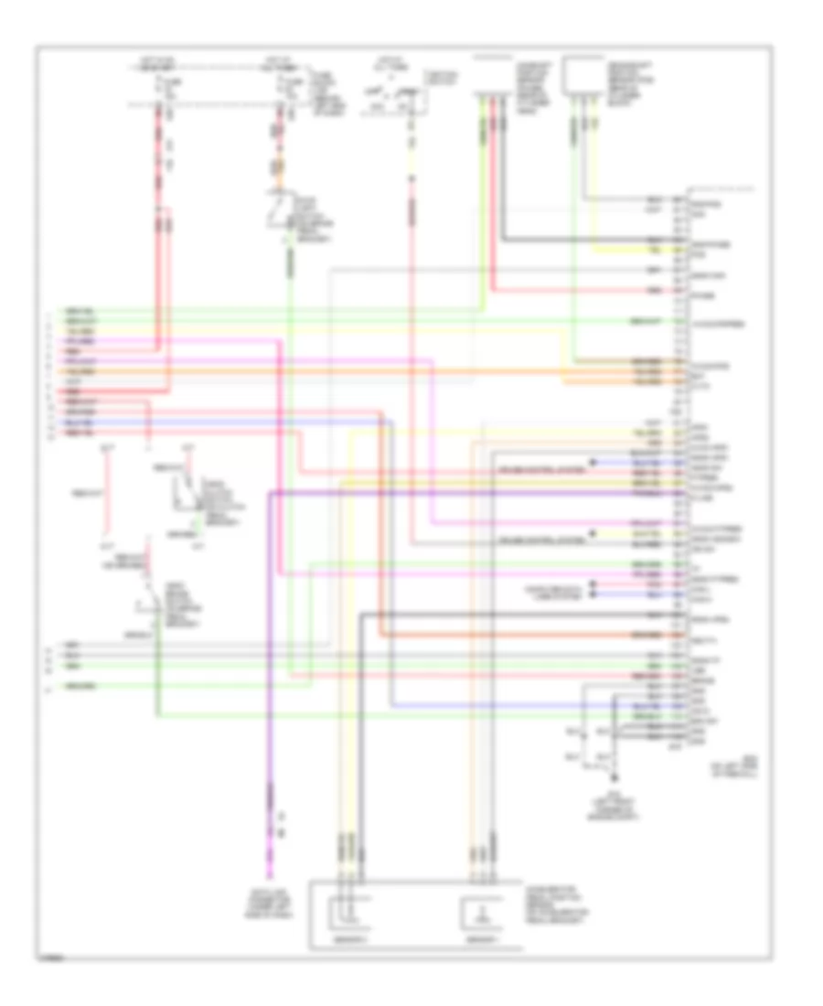
Horn Wiring Diagram for Nissan 240SX SE 1994
List of elements for Horn Wiring Diagram for Nissan 240SX SE 1994:
- Acc
- Accelerator pedal position sensor (on accelerator pedal bracket)
- Aps1
- Aps2
- Ascd brake switch (on brake pedal bracket)
- Ascd clutch switch (on clutch pedal bracket)
- Ascd sw
- Avcc-aps1
- Avcc2 ftpres
- Avcc2-aps2
- Avcc2-pdpres
- Avcc2-pos
- Bat
- Bnc sw
- Brake
- Camshaft position sensor (phase) (rear of cylinder head)
- Can-h
- Can-l
- Cdvc
- Computer data lines system
- Crankshaft position sensor (pos) (rear of cylinder block)
- Cruise control system
- Cvt
- Cvtc
- Data link connector (under left side of dash)
- E15 (left front corner of engine compt)
- E16
- E17
- E39
- Ecm (on left side of firewall)
- F10
- F25
- Ftpres
- Fuse 10a
- Fuse 15a
- Fuse block (j/b) (behind left end of dash)
- Gnd
- Gnd-phase
- Gnd-pos
- Gnda aps1
- Gnda aps2
- Gnda ascdsw
- Gnda ftpres
- Gnda knk
- Gnda-tf
- Hot at all times
- Hot in on or start
- Ig1
- Ign sw
- Ignition switch
- K-line
- Knk
- M/t
- Neut-h
- Off
- Phase
- Pnk
- Pos
- Red
- Sensor 1
- Sensor 2
- Start
- Stop light switch (on brake pedal bracket)
- Vbr
 Čeština
 Dansk
Dansk Deutsch
 Ελληνικά
 English
 Español
 Suomi
Suomi Français
 Français
 עברית
עברית Hrvatski
 Magyar
 Italiano
 日本語
日本語 한국어
한국어 Nederlands
 Polski
 Português
 Português
 Română
 Русский
 Slovenčina
 Slovenščina
 Svenska
 Türkçe
 中文 (中国)
 English