HORN
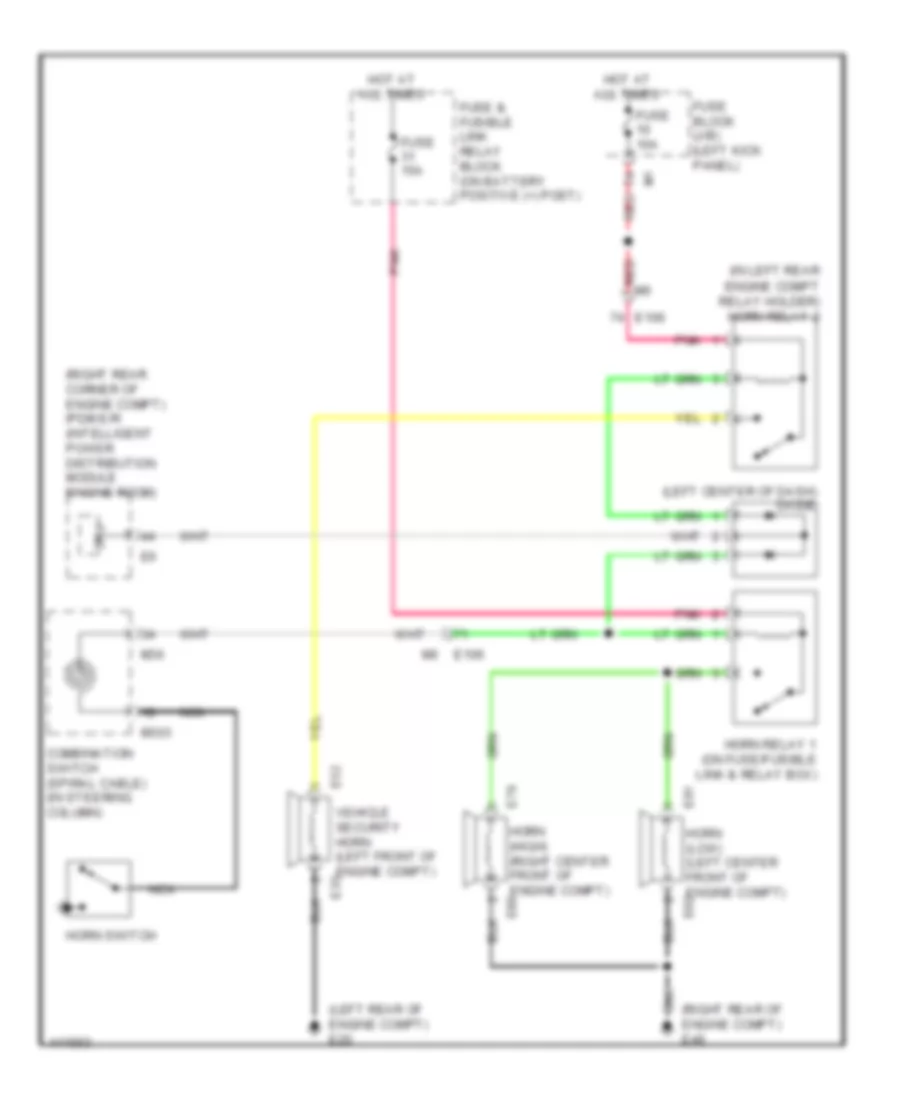
Horn Wiring Diagram for Nissan GT-R Black Edition 2014
List of elements for Horn Wiring Diagram for Nissan GT-R Black Edition 2014:
- (in left rear
- (left center of dash) diode
- (left rear of engine compt) e20
- (right rear corner of engine compt) ipdm e/r (intelligent power distribution module engine room)
- (right rear of engine compt) e46
- Combination switch (spiral cable) (in steering column)
- Cpu
- E106
- E32
- E79
- E81
- Engine compt relay holder) horn relay 2
- Fuse & fusible link relay block (on battery positive (+) post)
- Fuse 10a
- Fuse 15a
- Fuse block (j/b) (left kick panel)
- Horn (high) (right center front of engine compt) e80
- Horn (low) (left center front of engine compt) e82
- Horn relay 1 (on fuse/fusible link & relay box)
- Horn switch
- Hot at all times
- M303
- M36
- Nca
- Pnk
- Red
- Vehicle security horn (left front of engine compt) e33
 Čeština
 Dansk
Dansk Deutsch
 Ελληνικά
 English
 English
 Español
 Suomi
Suomi Français
 עברית
עברית Hrvatski
 Magyar
 Italiano
 日本語
日本語 한국어
한국어 Nederlands
 Polski
 Português
 Português
 Română
 Русский
 Slovenčina
 Slovenščina
 Svenska
 Türkçe
 中文 (中国)
 Français