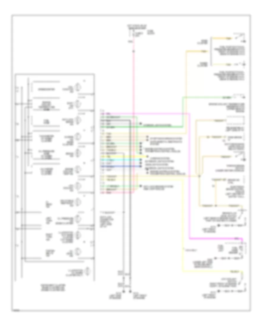
INSTRUMENT CLUSTER
Instrument Cluster Wiring Diagram for Chevrolet Beretta 1996
List of elements for Instrument Cluster Wiring Diagram for Chevrolet Beretta 1996:
- Anti-lock brake ind
- Anti-lock brakes system (abs lamp module)
- Base cluster
- Brake fluid level switch (left rear of engine compt, part of master cylinder)
- Brake ind
- Brake ind ctrl
- Charge ind (base cluster)
- Data link connector (partial) (left side of i/p)
- Daytime running lamps module (below radio)
- Electronic brake control module (left center of saftey wall)
- Engine controls system (powertrain control module)
- Engine coolant temp ind
- Engine coolant temperature gage
- Engine coolant temperature sender/switch (upper rear of engine)
- Exterior lights system
- Fasten belts ind
- Fuel gage
- Fuel gage sender
- Fuel pump switch/oil pressure sender/switch (front of engine-vin m) (rear of engine-vin 4)
- Fuel tank unit
- Fuse 9 20a
- Fuse block
- G110 (left front of engine)
- G112 (left side of engine)
- G300 (under left side of driver seat, near door sill)
- Gages cluster
- Headlights system
- Hi beam ind
- Hot in run, bulb test or start
- Illumination (2-w/ base cluster 3-w/ gages cluster)
- Illumination (w/ gages cluster only)
- Inflatable restraint ind
- Instrument cluster (base cluster-uh6) (gages cluster-ub3)
- Interior lights system
- Left turn ind
- Low coolant ind
- Low coolant switch (right front of engine compt, on surge tank)
- Mal- function ind
- Oil level ind
- Oil pressure gage (w/ gages cluster
- Oil pressure ind (base cluster)
- Park brake in
- Parking brake switch (under center console)
- Pnk
- Release relay (left side of i/p)
- Right turn ind
- Shift ind (m/t)
- Speedometer
- Starting/charging system
- Tachometer (w/ gages cluster)
- Tan
- Vin m only
- Voltmeter (w/ gages cluster)
- Warning system
 Čeština
 Dansk
Dansk Deutsch
 Ελληνικά
 English
 Español
 Suomi
Suomi Français
 Français
 עברית
עברית Hrvatski
 Magyar
 Italiano
 日本語
日本語 한국어
한국어 Nederlands
 Polski
 Português
 Português
 Română
 Русский
 Slovenčina
 Slovenščina
 Svenska
 Türkçe
 中文 (中国)
 English