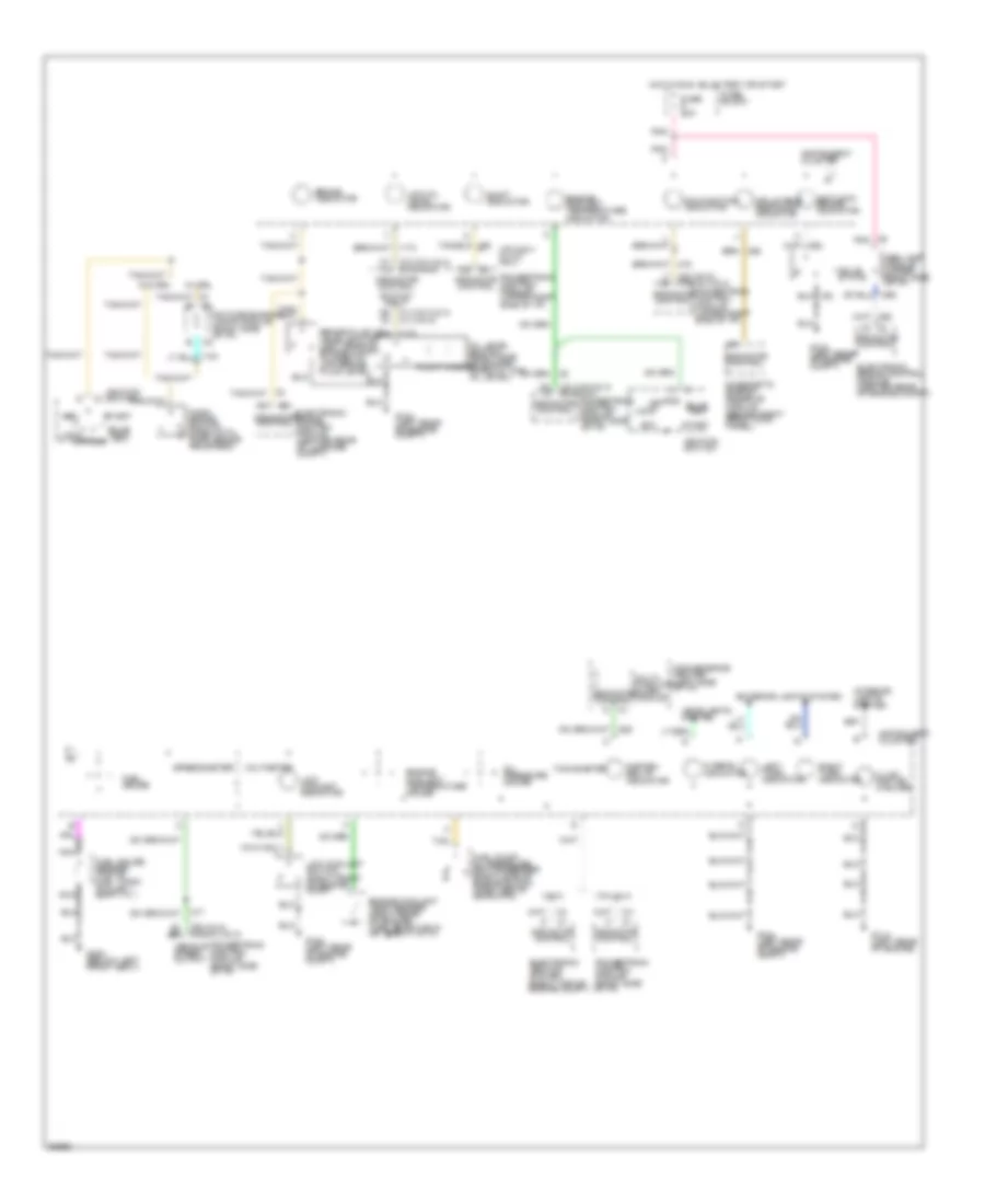
INSTRUMENT CLUSTER
Instrument Cluster Wiring Diagram, Base for Chevrolet Beretta Z26 1994
 https://portal-diagnostov.com/license.html
Automotive Electricians Portal FZCO
Automotive Electricians Portal FZCO
https://portal-diagnostov.com/license.html
https://portal-diagnostov.com/license.html
Automotive Electricians Portal FZCO
Automotive Electricians Portal FZCO
List of elements for Instrument Cluster Wiring Diagram, Base for Chevrolet Beretta Z26 1994:
-
- (not used)
- (vin a & 4) (vin m)
- (vin m) (vin 4 & a)
- (vin m) (vin a & 4)
- Abs lamp module (upper right side of i/p)
- Acc
- Antilock brake indicator
- Brake fluid level switch (left rear of engine compt) (closed w/ low brake fluid level)
- Brake indicator
- Bulb test
- C1 (vin a & 4) c1 (vin m)
- C2 c2
- C2 c3
- C3 (vin a & 4) c1 (vin m)
- C3 c2
- Charge indicator
- Convenience center (left side of i/p)
- Daytime running lamps module (right side of i/p)
- Diagnostic energy reserve module (behind right front kick panel)
- Electronic brake control module (center rear of engine compt)
- Electronic brake control module (center rear of luggage compt)
- Engine controls system
- Engine coolant temp sender (right rear of engine) (1365 @100 f,38 c) (55 @260 f,127 c)
- Engine coolant temperature gauge
- Engine coolant temperature indicator
- Exterior lights system
- Fasten belts indicator
- Float magnet
- Fuel gauge
- Fuel gauge sender (top of fuel tank) (full-90 ) (empty-0 )
- Fuel pump/ oil pressure switch/sender (right side of engine block) (open above 28kpa,4psi)
- Fuse 20a
- Fuse block
- G104 (left rear of engine compt)
- G114 (left rear of engine)
- G300 (below left front seat)
- Generator (right front of engine)
- Headlights system
- Hi beam indicator
- Hot in run, bulb test or start
- Ignition switch
- Illum- ination (2 bulbs)
- Indicator control
- Indicator control switch input
- Inflatable restraint indicator
- Instrument cluster
- Interior lights system
- Left turn indicator
- Lock
- Low coolant indicator
- Low coolant switch (right front of engine comp)
- Low oil level indicator
- Malfunction indicator
- Multi- function alarm module
- Nca
- Off
- Oil level switch (right side of engine) (open w/ low oil level)
- Oil pressure indicator
- Park brake switch (open with park brake released)
- Pnk
- Powertrain control module (right side of i/p)
- Powertrain control module (upper right side of i/p)
- Right turn indicator
- Run
- Shift indicator
- Solid state
- Speedometer
- Start
- Tan
- Vehicle speed output
- Vin a & 4 w/ m/t only
- Vin m only
- W/ drl
- W/o drl
Instrument Cluster Wiring Diagram, Gauges for Chevrolet Beretta Z26 1994
List of elements for Instrument Cluster Wiring Diagram, Gauges for Chevrolet Beretta Z26 1994:
-
- (vin a & 4) (vin m)
- (vin m) (vin 4 & a)
- (vin m) (vin a & 4)
- Abs lamp module (upper right side of i/p)
- Acc
- Antilock brake indicator
- Brake fluid level switch (left rear of engine compt) (closed w/ low brake fluid level)
- Brake indicator
- Bulb test
- C1 (vin a & 4) c1 (vin m)
- C2 c2
- C2 c3
- C3 (vin a & 4) c1 (vin m)
- C3 c2
- Convenience center (left side of i/p)
- Daytime running lamps module (right side of i/p)
- Diagnostic energy reserve module (behind right front kick panel)
- Electronic brake control module (center rear of engine compt)
- Electronic brake control module (center rear of luggage compt)
- Electronic ignition system (right top of engine compt)
- Engine coolant temp sender (right rear of engine) (1365 @100 f,38 c) (55 @260 f,127 c)
- Engine coolant temperature gauge
- Engine coolant temperature indicator
- Exterior lights system
- Fasten belts indicator
- Float magnet
- Fuel gauge
- Fuel gauge sender (top of fuel tank) (full-90 ) (empty-0 )
- Fuel pump/ oil pressure switch/sender (right side of engine block) (open above 28kpa,4psi)
- Fuse 20a
- Fuse block
- G104 (left rear of engine compt)
- G114 (left rear of engine)
- G300 (below left front seat)
- Headlights system
- Hi beam indicator
- Hot in run, bulb test or start
- Ignition switch
- Illum- ination (4 bulbs)
- Indicator control
- Indicator control switch input
- Inflatable restraint indicator
- Instrument cluster
- Interior lights system
- Left turn indicator
- Lock
- Low coolant indicator
- Low coolant switch (right front of engine comp)
- Low oil level indicator
- Malfunction indicator
- Multi- function alarm module
- Nca
- Off
- Oil level switch (right side of engine) (open w/ low oil level)
- Oil pressure gauge
- Park brake switch (open with park brake released)
- Pnk
- Powertrain control module (right side of i/p)
- Powertrain control module (upper right side of i/p)
- Right turn indicator
- Run
- Shift indicator
- Solid state
- Speedometer
- Start
- Tachometer
- Tan
- Vehicle speed output
- Vin 4 & a
- Vin a & 4 w/ m/t only
- Vin m
- Vin m only
- Voltmeter
- W/ drl
- W/o drl

 Čeština
 Dansk
Dansk Deutsch
 Ελληνικά
 English
 Español
 Suomi
Suomi Français
 Français
 עברית
עברית Hrvatski
 Magyar
 Italiano
 日本語
日本語 한국어
한국어 Nederlands
 Polski
 Português
 Português
 Română
 Русский
 Slovenčina
 Slovenščina
 Svenska
 Türkçe
 中文 (中国)