INSTRUMENT CLUSTER
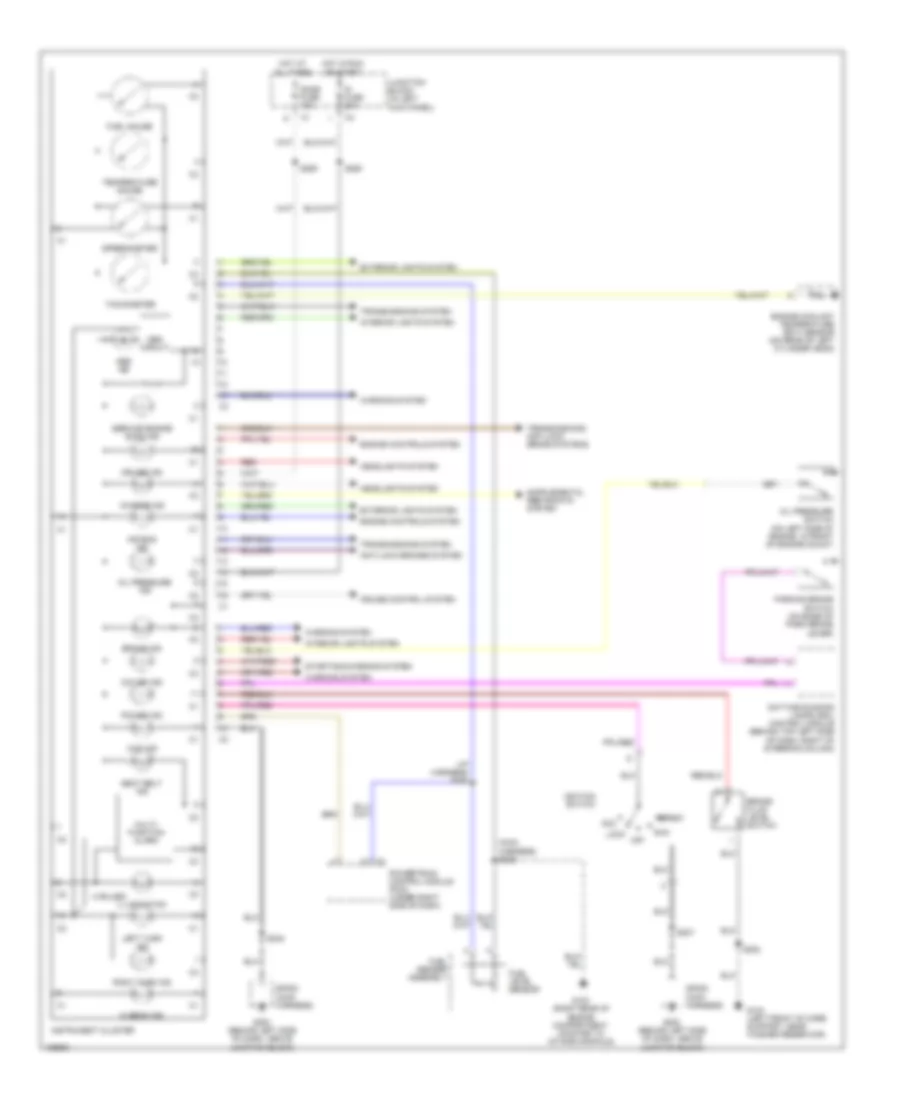
Instrument Cluster Wiring Diagram for Chevrolet Tracker 2004
List of elements for Instrument Cluster Wiring Diagram for Chevrolet Tracker 2004:
- (4 bulbs)
- (i/p harness) s258
- (main harness) s206
- 4wd ind
- Abs circuit
- Abs ind
- Acc
- Air bag ind
- Anti-lock brakes system
- Brake fluid level switch
- Brake ind
- Charge ind
- Cruise control system
- Cruise ind
- Daytime running lamps (drl) control module (behind top left side of dash, right of steering column)
- Dome fuse 10a
- Engine controls system
- Engine coolant temperature (ect) sensor (on rear of left cylinder head)
- Exterior lights system
- Fuel gauge
- Fuel level sensor
- Fuel sender assembly
- G103 (right rear of engine compartment, mounted to intake manifold)
- G104 (left front of core support, near washer reservoir)
- G200 (behind left side of dash, above junction block)
- Headlights system
- Hi beam ind
- Hot at all times
- Hot in run or start
- Ig fuse 20a
- Ignition switch
- Illumination
- Instrument cluster
- Interior lights system
- Junction block (in left kick panel)
- Left turn ind
- Lock
- Multi- function alarm
- O/d off ind
- Off
- Oil pressure ind
- Oil pressure switch (on left side of engine, in front of engine mount)
- Parking brake switch (on base of park brake lever)
- Power ind
- Powertrain control module (pcm) (under right side of dash)
- Red
- Right turn ind
- Run
- S202
- S207
- S248
- S250
- S255
- Seat belt ind
- Service engine soon ind
- Sp200 (main harness)
- Speedometer
- Start
- Starting/charging system
- Tachometer
- Temperature gauge
- Transmissions system
- Transmissions, anti-lock brake systems
- Warning system
 Čeština
 Dansk
Dansk Deutsch
 Ελληνικά
 English
 English
 Suomi
Suomi Français
 Français
 עברית
עברית Hrvatski
 Magyar
 Italiano
 日本語
日本語 한국어
한국어 Nederlands
 Polski
 Português
 Português
 Română
 Русский
 Slovenčina
 Slovenščina
 Svenska
 Türkçe
 中文 (中国)
 Español