INSTRUMENT CLUSTER
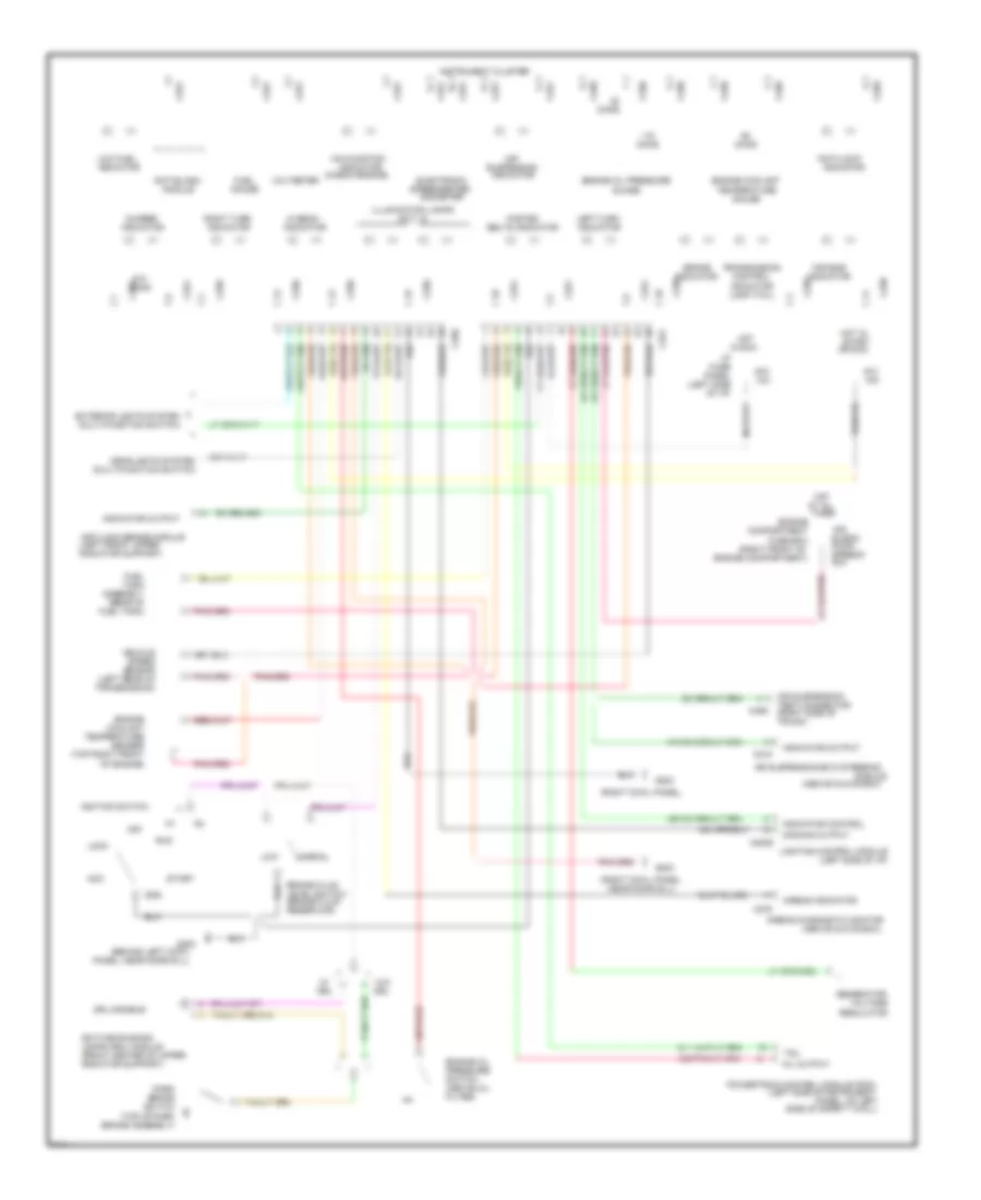
Digital Display Wiring Diagram (1 of 2) for Ford Crown Victoria 1996
 https://portal-diagnostov.com/license.html
Automotive Electricians Portal FZCO
Automotive Electricians Portal FZCO
https://portal-diagnostov.com/license.html
https://portal-diagnostov.com/license.html
Automotive Electricians Portal FZCO
Automotive Electricians Portal FZCO
List of elements for Digital Display Wiring Diagram (1 of 2) for Ford Crown Victoria 1996:
- #18
- (above oil filter)
- (behind right side of i/p)
- (front of right front fender
- (in fluid reservoir)
- (left rear
- (left rear of engine compartment)
- (left side of safety wall)
- (rear of
- (right side of trunk)
- (top right
- 15a
- 17400 ohm
- 2670 ohm
- 28 thru 36
- 7320 ohm
- Air bag diagnostic monitor
- Air susp in
- Air suspension
- Air suspension/evo steering module
- Airbag ind in
- All times
- Apron, right side of battery)
- Assembly
- Automatic
- Battery power
- C215
- C227
- C254 & c255
- C256
- C276
- Charge ind in
- Control (eatc)
- Coolant temp sens in
- Deck lid open
- Dim display in
- Door ajar in
- E/m
- Electronic
- Engine coolant temperature
- Engine oil pressure switch
- English/metric
- Exterior lights system
- Fasten belts in
- Front of engine)
- Fuel
- Fuel flow rate in
- Fuel level in
- Fuel tank)
- Fuse
- G101
- Headlights system
- Hi beam in
- Hot at
- Hot in run
- I/p
- Ind
- Instrument cluster
- Interior
- Interior lights system
- Left turn signal
- Lights
- Low fluid switch
- Low washer fluid in
- Malfunction ind
- Message center switch assembly
- Module
- Of transmission)
- Oil pres ind in
- Out
- Output
- Panel
- Power ground
- Powertrain control module
- Prndl illum
- Red 506
- Reset
- Right turn signal
- Select
- Sens ground
- Sensor
- Sound tone output
- Speed control in
- Speed control servo assembly
- Switch assembly in
- Switched power
- System
- Tank
- Temperature
- Test connector
- Trans ctrl ind lt
- Vehicle speed
- Vehicle speed in +
- Windshield washer
Digital Display Wiring Diagram (2 of 2) for Ford Crown Victoria 1996
List of elements for Digital Display Wiring Diagram (2 of 2) for Ford Crown Victoria 1996:
- #15
- (above glove box)
- (behind right
- (center rear
- (left front door)
- (left side of i/p)
- (part of
- (right cowl panel,
- 10a
- Air suspension
- Ajar
- Ajar lamp output
- C2026
- C2027
- C2029
- C216
- C518
- Closed
- Cowl panel,
- Decklid jar
- Door
- Door ajar
- Driver's ajar switch
- Driver's door
- Evo steering module
- Front
- Fuse
- G203
- G407
- Generator/voltage regulator
- Hot
- I/p
- In run
- Input
- Latch
- Latch assembly)
- Left
- Lid
- Lighting control module
- Module
- Near door sill)
- Of trunk
- On support)
- Panel
- Pass. ajar switch
- Rear
- Right
- Seat belt
- Seatbelt ind out
- Seatbelt switch
- Solenoid ajar switch
- Switch
- Tone request
- Trunk lid release
Instrument Cluster Wiring Diagram, Analog Cluster with Gasoline for Ford Crown Victoria 1996
List of elements for Instrument Cluster Wiring Diagram, Analog Cluster with Gasoline for Ford Crown Victoria 1996:
- "air bag"
- "anti/lock"
- #13
- #15
- (above glove box)
- (above oil
- (behind left cowl
- (brake fluid
- (check engine)
- (front center of upper
- (left front upper
- (left rear of
- (left side
- (left side of i/p)
- (left side of instrument
- (multi/function switch)
- (qty. 6)
- (rear of
- (right cowl panel,
- (right front of
- (right side of
- (top of park
- (top right front
- 10a
- 15a
- 30a
- Acc
- Air
- Air suspension
- Air suspension/evo steering
- Airbag diagnostic monitor
- Airbag indicator
- Anti/lock brake module
- Anti/slosh
- Assembly
- At all
- Belts indicator
- Brake
- Brake assembly)
- Brake fluid
- C2029
- C215
- C250
- C251
- C276
- C459
- Charge
- Compartment
- Control
- Coolant
- Daytime running
- Dimming output
- Drl
- Drl disable
- Electronic
- Engine
- Engine compartment)
- Engine coolant
- Engine oil
- Engine oil pressure
- Exterior lights system
- Fasten
- Filter)
- Fuel
- Fuel tank)
- Fuse
- Fuse box
- G200
- G203
- Gauge
- Generator/
- Gnd
- Guage
- Headlights system
- Hi beam
- Hot
- Hot in
- I/p
- Ignition switch
- Illumination lamps
- In run
- Indicator
- Indicator control
- Indicator output
- Instrument cluster
- Lamp (tcil)
- Lamps (drl) module
- Left turn
- Level switch
- Lighting control module
- Lock
- Low
- Low fuel
- Malfunction
- Mil output
- Module
- Near door sill)
- Normal
- Odometer
- Of engine)
- Of i/p)
- Off
- Ohms
- Or run
- Panel
- Panel, near door sill)
- Panel, on left
- Park
- Powertrain control module (pcm)
- Pressure
- Pump/
- Radiator support)
- Regulator
- Reservoir)
- Right turn
- Run
- Sender
- Sensor
- Side of safety wall)
- Speed
- Speedo
- Speedometer/
- Start
- Suspension
- Suspn
- Switch
- Tank
- Tcil
- Temperature
- Test connector
- Times
- Transmission
- Transmission)
- Trunk)
- Vehicle
- Voltage
- Voltmeter
- W/o
Instrument Cluster Wiring Diagram, Analog Cluster with Natural Gas for Ford Crown Victoria 1996
List of elements for Instrument Cluster Wiring Diagram, Analog Cluster with Natural Gas for Ford Crown Victoria 1996:
- "air bag"
- "anti/lock"
- #15
- (above glove box)
- (above oil
- (behind left cowl
- (brake fluid
- (check engine)
- (front center of upper
- (front of
- (left front upper
- (left rear of
- (left side
- (left side of i/p)
- (left side of instrument
- (multi/function switch)
- (qty. 6)
- (right cowl panel,
- (right front of
- (right side of
- (top of park
- (top right front
- 10a
- 30a
- Acc
- Air
- Air suspension
- Air suspension/evo steering
- Airbag diagnostic monitor
- Airbag indicator
- Anti/lock brake module
- Anti/slosh
- Belts indicator
- Brake
- Brake assembly)
- Brake fluid
- C2029
- C215
- C250
- C251
- C276
- C459
- Charge
- Cluster
- Compartment
- Compartment)
- Control
- Coolant
- Daytime running
- Dimming output
- Drl
- Drl disable
- Electronic
- Engine
- Engine compartment)
- Engine coolant
- Engine oil
- Engine oil pressure
- Exterior lights system
- Fasten
- Filter)
- Fuel
- Fuse
- Fuse box
- G200
- G203
- Gauge
- Generator/
- Gnd
- Ground
- Guage
- Headlights system
- Hi beam
- Hot at all times
- Hot in run
- I/p
- Ignition switch
- Illumination lamps
- Indicator
- Indicator control
- Indicator output
- Instrument cluster
- Lamp (tcil)
- Lamps (drl) module
- Left turn
- Level switch
- Lighting control module
- Lock
- Low
- Low fuel
- Malfunction
- Mil output
- Module
- Module (fim)
- Near door sill)
- Normal
- Odometer
- Of engine)
- Of i/p)
- Off
- Ohms
- Panel
- Panel, near door sill)
- Panel, on left
- Park
- Power
- Powertrain control module (pcm)
- Pressure
- Pump/
- Radiator support)
- Regulator
- Reservoir)
- Right turn
- Run
- Sender
- Sensor
- Side of safety wall)
- Signal
- Speed
- Speedo
- Speedometer/
- Start
- Suspension
- Suspn
- Switch
- Tcil
- Temperature
- Test connector
- Transmission
- Transmission)
- Trunk)
- Vehicle
- Voltage
- Voltmeter
- W/o
Warning Lights Wiring Diagram for Ford Crown Victoria 1996
List of elements for Warning Lights Wiring Diagram for Ford Crown Victoria 1996:
- (left cowl panel, near door sill)
- Acc
- Anti- lock brake module (left front radiator support)
- Anti- lock indicator
- Brake fluid level switch
- Brake indicator
- C162
- C2026
- Daytime running lamps (drl) module (center front of vehicle)
- Fuse 15a
- G200
- Gnd
- Hazard warning indicator
- Hot in start or run
- I/p fuse panel
- Ignition switch
- Lighting control module (left side of i/p)
- Lock
- Off
- Park brake switch (top of park brake assembly)
- Run
- Start
- W/ drl
- W/o drl
- Warning lamps module

 Čeština
 Dansk
Dansk Deutsch
 Ελληνικά
 English
 Español
 Suomi
Suomi Français
 Français
 עברית
עברית Hrvatski
 Magyar
 Italiano
 日本語
日本語 한국어
한국어 Nederlands
 Polski
 Português
 Português
 Română
 Русский
 Slovenčina
 Slovenščina
 Svenska
 Türkçe
 中文 (中国)