INSTRUMENT CLUSTER
Instrument Cluster Wiring Diagram for Ford F550 Super Duty 2004
 https://portal-diagnostov.com/license.html
Automotive Electricians Portal FZCO
Automotive Electricians Portal FZCO
https://portal-diagnostov.com/license.html
https://portal-diagnostov.com/license.html
Automotive Electricians Portal FZCO
Automotive Electricians Portal FZCO
List of elements for Instrument Cluster Wiring Diagram for Ford F550 Super Duty 2004:
- (6.0l: left side of engine compt) (except 6.0l: on left side of firewall) powertrain control module (pcm)
- (behind left side of dash, on park brake assembly) parking brake switch
- (excursion w/ diesel, pickup w/o california emissions)
- (excursion w/ gasoline, pickup w/ california emissions)
- (in taillamps harness, near breakout for fuel tank selector valve) s400
- (left rear of cab)
- (left rear of cab) fuel tank selector valve
- (on vehicle floor, in left front footwell) g300
- 31 (or 1308)
- 4wd high ind
- 4wd low ind
- Abs ind
- Air bag ind
- Air filter ind
- Air filter sensor (diesel) (on left side of engine compartment)
- Anti-lock brakes system
- Anti-theft on ind (excursion)
- Anti-theft system
- Battery saver relay
- Brake fluid level switch (on brake fluid reservoir)
- C1381a
- C175
- C205b
- C220a
- C220b
- C220c
- C270a
- C270b
- Central junction box (cjb) (behind lower left side of dash)
- Charge ind
- Check engine ind
- Computer data lines system
- Cruise control system
- Defogger system
- Diesel
- Diesel gasoline
- Engine coolant temperature
- Excursion
- Exterior lights system
- Fuel gauge
- Fuel tank selector switch
- Fuel tank selector valve
- Fuel tank unit
- Fuse 10a
- Fuse 15a
- G100 (at left rear side of engine compartment)
- G202 (behind left side of dash)
- G300 (on vehicle floor, in left front footwell)
- Gasoline
- Headlights system
- High beam ind
- Hot at all times
- Hot in run or acc
- Hot in start or run
- Illumination (6 bulbs)
- Instrument cluster
- Interior lamps relay
- Interior lights system
- Interior lights, power windows systems
- Lh turn signal ind
- Low brake fluid level/ park brake ind
- Low oil pressure ind
- Low oil pressure/ high coolant temperature ind
- Main light switch
- Microprocessor
- Nca
- Oil pressure switch (5.4l: on left front of engine) (6.0l: top center of engine) (6.8l: lower left side of engine)
- Overhead console
- Pickup
- Powertrain control module (pcm) (left side of engine compt)
- Primary fuel sender (on fuel tank)
- Rh turn signal ind
- S102
- S201
- S208 (w/ overhead console) (in main harness, near breakout for c264)
- S217
- S254
- S271
- S278 (in main harness, at breakout for instrument cluster)
- S298 (in main harness, at breakout for instrument cluster)
- Secondary fuel sender (on fuel tank)
- Speed control ind
- Speed control servo (in right side of engine compt)
- Speedometer
- Starting/charging system
- Tachometer
- Transmission fluid temperature
- Transmissions system
- Trip computer module (on front center of roof)
- W/ auxiliary fuel tank
- W/ roof opening panel
- W/o auxiliary fuel tank
- W/o roof opening panel
- W/o roof opening panel w/ roof opening panel
- Wait to start ind (diesel)
- Warning system
- Water in fuel ind
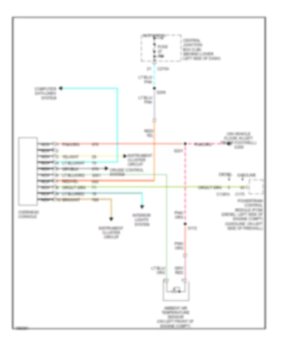
Overhead Console Wiring Diagram for Ford F550 Super Duty 2004
List of elements for Overhead Console Wiring Diagram for Ford F550 Super Duty 2004:
- (on vehicle floor, in left front footwell) g300
- Ambient air temperature sensor (on left front of engine compt)
- C1381a
- C175
- C270a
- Central junction box (cjb) (behind lower left side of dash)
- Computer data lines system
- Cruise control system
- Diesel gasoline
- Fuse 15a
- Hot in run
- Instrument cluster circuit
- Interior lights system
- Nca
- Overhead console
- Powertrain control module (pcm) (diesel: left side of engine compt) (gasoline: on left side of firewall)
- S172
- S201
- S206

 Čeština
 Dansk
Dansk Deutsch
 Ελληνικά
 English
 Español
 Suomi
Suomi Français
 Français
 עברית
עברית Hrvatski
 Magyar
 Italiano
 日本語
日本語 한국어
한국어 Nederlands
 Polski
 Português
 Português
 Română
 Русский
 Slovenčina
 Slovenščina
 Svenska
 Türkçe
 中文 (中国)