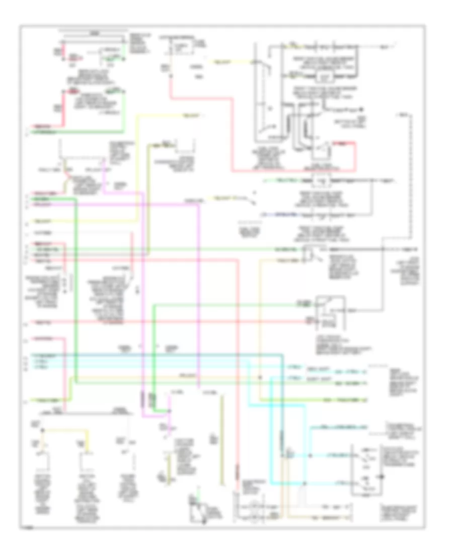
INSTRUMENT CLUSTER
Instrument Cluster Wiring Diagram (1 of 2) for Ford Pickup F350 1996
 https://portal-diagnostov.com/license.html
Automotive Electricians Portal FZCO
Automotive Electricians Portal FZCO
https://portal-diagnostov.com/license.html
https://portal-diagnostov.com/license.html
Automotive Electricians Portal FZCO
Automotive Electricians Portal FZCO
List of elements for Instrument Cluster Wiring Diagram (1 of 2) for Ford Pickup F350 1996:
- (behind bottom of right cowl panel)
- (behind lower center of i/p)
- (behind lower right side of i/p, below glove compt)
- (left front of engine compt, on upper radiator support)
- (left side of safety wall)
- 20 ohms
- 4x4 ind.
- 500 ohms
- A10
- A11
- A12
- A13
- A14
- Acc
- Air bag ind.
- Anti-lock brake ind.
- B10
- B11
- B12
- B13
- Bat
- Brake fluid level
- Brake warning ind.
- Charge ind.
- Check engine ind.
- Chime module
- Conn a
- Conn b
- Conn c
- Control
- Coolant temp. gauge
- Diesel only
- Diesel warning lamps display
- Enable psom programming connector
- Engine warning ind.
- Except diesel
- Exterior lights system (multi-function switch)
- Fasten seat belt ind.
- Fuel gauge
- Fuel water switch (right side of engine, on bottom of fuel filter/heater)
- Fuse 10a
- Fuse 15a
- Fuse 4a
- Fuse panel
- G108
- G200 (behind bottom of left cowl panel)
- G203
- Gas over 8500 gvwr
- Gas under 8500 gvwr and all diesel
- Generator/ voltage regulator
- Gnd
- Headlights system (multi-function switch)
- Hi beam ind.
- Hot at all times
- Hot in run
- Hot in run or start
- Hot w/ light sw in head or park
- Ign (run)
- Ignition switch
- Illumination lamps
- Instrument cluster
- Left turn ind.
- Lock
- Low range ind.
- Mechanical shift only
- Module
- Off
- Oil press. gauge
- Overheat warning switch (left front of engine)
- Plugged fuel filter ind.
- Plugged fuel filter switch (right side of engine, in fuel filter/heater housing)
- Powertrain
- Powertrain control module (left side of safety wall)
- Programmable speedometer/ odometer module
- Red
- Red/pnk
- Right turn ind.
- Run
- Solid state
- Speed control servo/ amplifier assembly (left side of engine compt, near brake master cylinder)
- Start
- Tachometer
- Test
- Volt- meter
- Vss input
- Vss output
- Vss return
- W/ tach
- W/o tach
- Wait-to-start ind.
- Warning
- Water-in- fuel ind.
- Water-in- fuel sensor (right side of engine, near fuel filter)
Instrument Cluster Wiring Diagram (2 of 2) for Ford Pickup F350 1996
List of elements for Instrument Cluster Wiring Diagram (2 of 2) for Ford Pickup F350 1996:
- (5.0l & 5.8l- (left rear of engine, near intake manifold)
- (5.0l & 5.8l-lower left front of of engine, near oil filter) (7.3l & 7.5l-top center rear of engine)
- (behind right side of i/p, behind glove compt)
- (below right center of
- (below right rear of
- (left rear of engine
- (left rear of engine compt,
- 4x2
- 4x4
- 4x4 hi/low indicator switch (below vehicle, on front of transfer case)
- Air bag diagnostic monitor (behind left side of i/p)
- Brake fluid level switch (left rear of engine compt, on brake fluid reservoir)
- Compt, on bracket)
- Data link connector
- Daytime running lamps module (front left side of lower radiator support)
- Diesel
- Diesel only
- Diesel w/ tach
- Elect. shift
- Electronic shift control module (behind right cowl panel)
- Electronic shift control switch
- Engine coolant temperature sender (4.9l-right side of engine) (except 4.9l-top left front of engine)
- Engine oil pressure switch (4.9l-lower left rear of engine, near oi filter)
- Front
- Front tank fuel gauge sender
- Front tank fuel pump/ fuel gauge sender (below right center of vehicle, in front fuel tank)
- Fuel tank selector switch
- Fuel tank selector valve (under left center of vehicle, on left frame rail)
- Fuse 6 15a
- Fuse panel
- G108 (left front of engine compartment, on upper radiator support)
- G200 (bottom of left cowl panel)
- Gas
- Gasoline
- Hot in acc or run
- Ignition coil (4.9l-left front of engine, forward distributor)
- Ignition control module (left rear of engine compt, on fender apron)
- Link connector
- Low
- Low vacuum warning switch (diesel only) (right side of engine compt., behind right battery)
- Mech. shift
- Nca
- On bracket)
- Only
- Park brake switch
- Power- train control module (left side of safety wall)
- Powertrain control module (left side of safety wall)
- Powertrain control module (left side of safety wall)
- Rabs data
- Rear
- Rear anti-lock brake module
- Rear axle speed sensor (on axle assembly)
- Rear tank fuel gauge sender
- Rear tank fuel pump/ fuel gauge sender (below right rear of vehicle, in rear fuel tank)
- Red
- Red/
- Red/ pnk
- Red/pnk
- Solid state
- Vehicle, in front fuel tank)
- Vehicle, in rear fuel tank)
- W/ drl
- W/o drl

 Čeština
 Dansk
Dansk Deutsch
 Ελληνικά
 English
 Español
 Suomi
Suomi Français
 Français
 עברית
עברית Hrvatski
 Magyar
 Italiano
 日本語
日本語 한국어
한국어 Nederlands
 Polski
 Português
 Português
 Română
 Русский
 Slovenčina
 Slovenščina
 Svenska
 Türkçe
 中文 (中国)