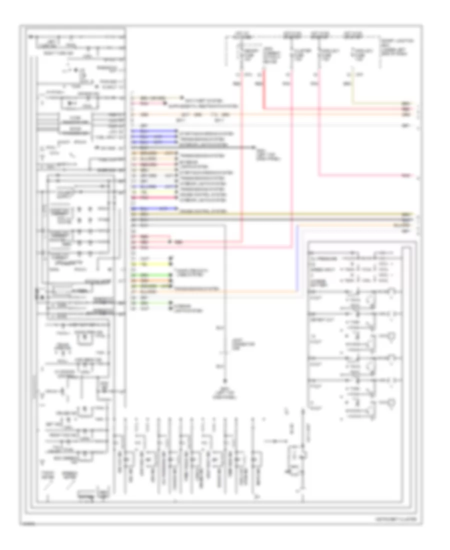
INSTRUMENT CLUSTER
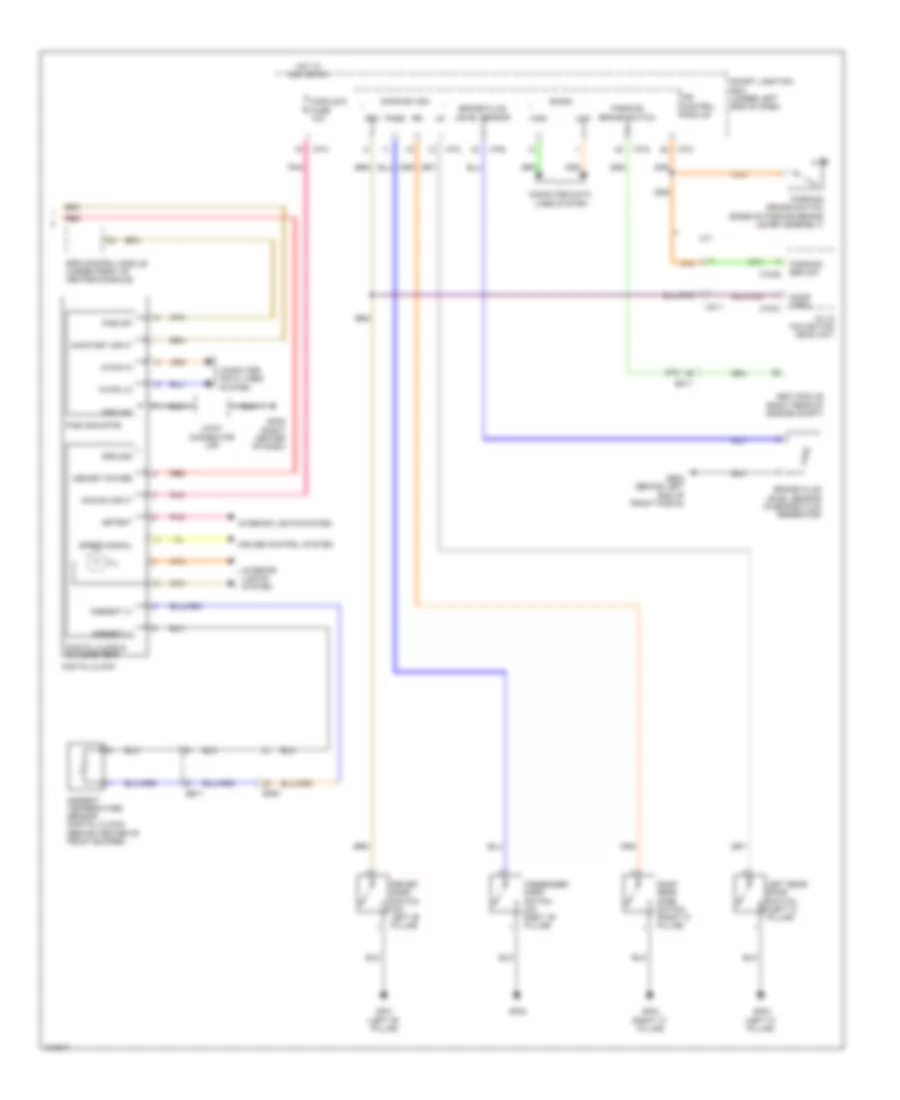
Instrument Cluster Wiring Diagram, MD (1 of 3) for Hyundai Elantra Limited 2014
 https://portal-diagnostov.com/license.html
Automotive Electricians Portal FZCO
Automotive Electricians Portal FZCO
https://portal-diagnostov.com/license.html
https://portal-diagnostov.com/license.html
Automotive Electricians Portal FZCO
Automotive Electricians Portal FZCO
List of elements for Instrument Cluster Wiring Diagram, MD (1 of 3) for Hyundai Elantra Limited 2014:
- (a/t)
- (m/t)
- (w/ conventional)
- (w/ conventional) key out ind
- 5v regulator
- Abs ind
- Active eco sw
- Air bag ind
- Altl output
- Anti-theft system
- Auto stop (green) ind
- B-can
- Battery charger
- Buzzer
- C-can
- Charge ind
- Check engine ind
- Cluster 1 fuse 7.5a
- Computer data lines system
- Constant current circuit
- Cruise control system
- Cruise ind
- D out
- Dc-dc
- Dc/d power
- Detent out
- Dial ill
- Door open ind
- Ec11
- Eco (green) ind
- Eeprom
- Em11
- Esc ind
- Esc off ind
- Exterior lights system
- Front fog ind
- Fuel (+)
- Fuel (-)
- Gm01 (left top dash panel)
- High
- High beam ind
- Hot at all times
- Hot in on or start
- I/f
- I/p-f
- I/p-h
- Immo ind
- Input switch
- Instrument cluster
- Interface
- Interior lights system
- Joint connector ume
- Lcd ill
- Leak current autocut device
- Left turn ind
- Low
- Low fuel ind
- Mdps ind
- Memory fuse 10a
- Micom
- Module 2 fuse 7.5a
- Module 3 fuse 7.5a
- N out
- Oil press
- Oil pressure ind
- Oled
- Output
- Output 4 pulses
- P out
- Parking brake ind
- Pnk
- Pointer ill
- Pwr gnd
- R input
- R out
- Red
- Rheostat down switch
- Rheostat out
- Rheostat up switch
- Right turn ind
- S out
- Seat belt ind
- Seg lcd
- Set ind
- Sig gnd
- Smart junction box (under left end of dash)
- Speed input
- Speedo- meter
- Starting/charging system
- Sw gnd
- Tacho- meter
- Tail on ind
- Temp high ind
- Tpms tread ind
- Transceiver
- Transmissions system
- Trunk open ind
- Vision) (w/ super oled lcd
- W/ conventional
- W/ super vision
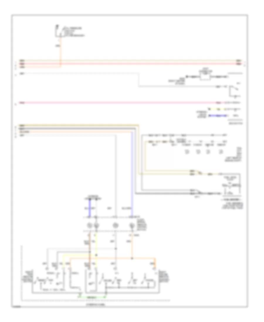
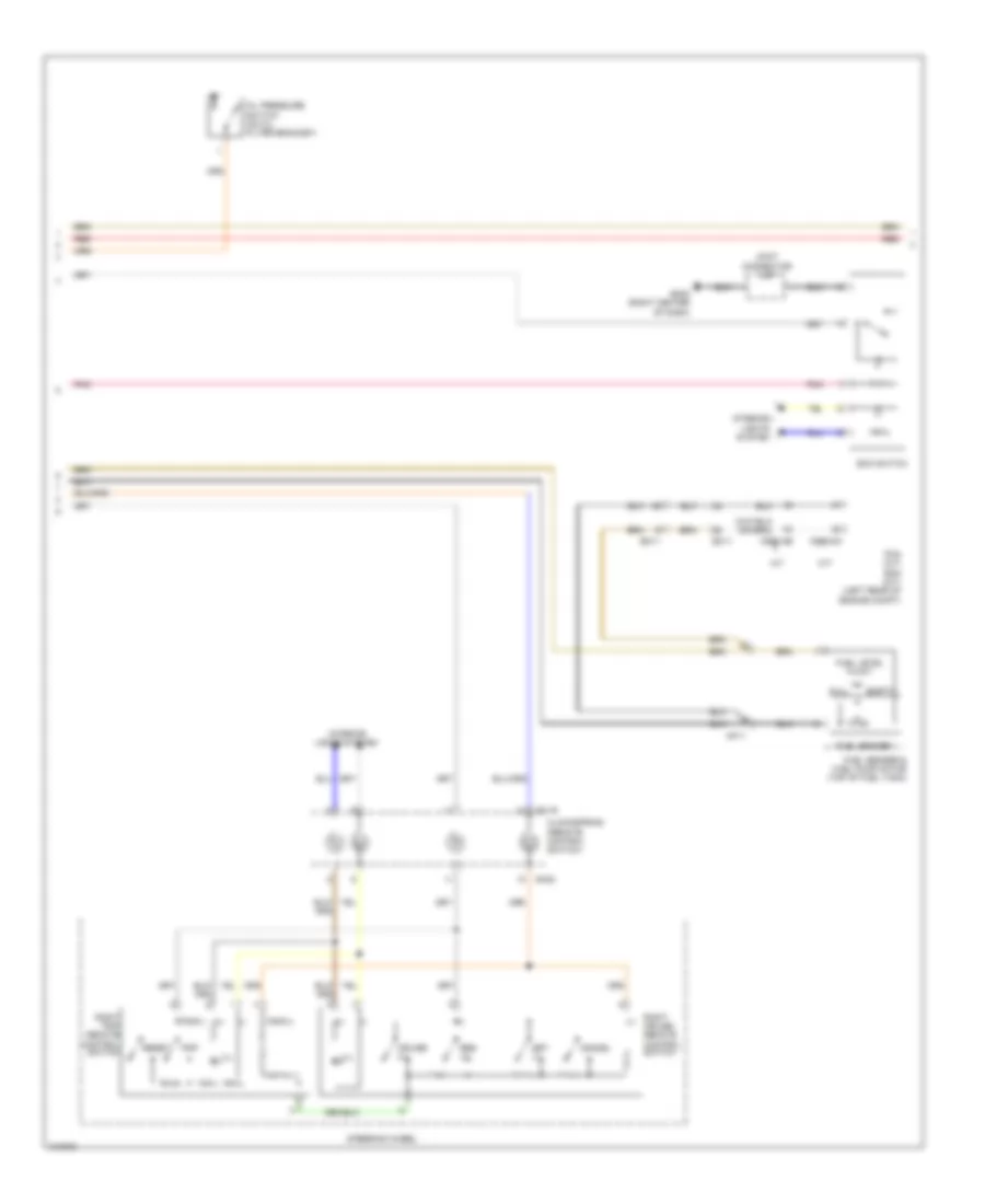
Instrument Cluster Wiring Diagram, MD (2 of 3) for Hyundai Elantra Limited 2014
List of elements for Instrument Cluster Wiring Diagram, MD (2 of 3) for Hyundai Elantra Limited 2014:
- (+)
- (-)
- (remote control switch)
- 1.8l a/t
- 1.8l m/t
- 2.0l a/t
- 2.0l m/t
- C100-aa
- C100-mk
- C600-ab
- C600-mk
- Cancel
- Clock spring
- Cruise
- Ec11
- Eco switch
- Em11
- Empty
- Fuel level float
- Fuel sender
- Fuel sender & fuel pump motor (top of fuel tank)
- Full
- Gm02 (right center of dash)
- Ill
- Interior lights system
- Joint connector umf
- M01-r
- Mf11
- Mm02
- Oil pressure switch (on oil filter bracket)
- Pcm (a/t) ecm (m/t) (left rear of engine compt)
- Pnk
- Red
- Res (+)
- Reset
- Right cruise remote control switch
- Right trip remote control switch
- Set (-)
- Steering wheel
- Trip
- Trip(+)
- Trip(-)
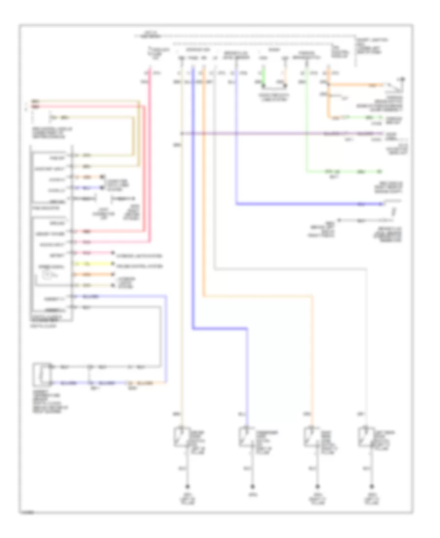
Instrument Cluster Wiring Diagram, MD (3 of 3) for Hyundai Elantra Limited 2014
List of elements for Instrument Cluster Wiring Diagram, MD (3 of 3) for Hyundai Elantra Limited 2014:
- A/v & navigation head unit
- Acc/on input
- Ambient (+)
- Ambient (-)
- Ambient temperature sensor (digital clock) (behind center of front bumper)
- B-can
- Brake fluid level sensor
- Brake fluid level sensor (in brake fluid reservoir)
- Computer data lines system
- Cruise control system
- Detent
- Digital clock
- Digital clock & outside temp
- Door open
- Door sw sig
- Driver door switch (on left "b" pillar)
- Drv
- Ee11
- Em11
- Em61
- Esc module (right rear of engine compt)
- Ge02 (behind left end of front fascia)
- Gf01 (left "b" pillar)
- Gf02
- Gf03 (left "c" pillar)
- Gf04 (right "c" pillar)
- Gm02 (right center of dash)
- Ground
- High
- Hot in acc or on
- I/p-c
- I/p-e
- I/p-g
- I/p-h
- Ill
- Interior lights system
- Ips control module
- Joint connector umf
- Left rear door switch (left "c" pillar)
- Low
- M-can hi
- M-can lo
- M/t
- M15-b
- M15-c
- Memory power
- Mf11
- Module 6 fuse 10a
- On/start input
- Pab indicator
- Pab off
- Parking brake switch
- Parking brake switch (base of parking brake lever assembly)
- Parking brk sw
- Pass
- Passenger door switch (on right "b" pillar)
- Pnk
- Red
- Right rear door switch (right "c" pillar)
- Smart junction box (under left end of dash)
- Speed signal
- Srs control module (under front of center console)
Instrument Cluster Wiring Diagram, UD (1 of 3) for Hyundai Elantra Limited 2014
List of elements for Instrument Cluster Wiring Diagram, UD (1 of 3) for Hyundai Elantra Limited 2014:
- (a/t)
- (m/t)
- (under left end of dash)
- 4p out
- Abs ind
- Air bag ind
- Alt l out
- Anti-theft system
- B-can
- Brake ind
- Buzzer
- C-can
- Charge battery
- Charge ind
- Check engine ind
- Cluster fuse 7.5a
- Computer data lines system
- Constant current
- Cruise control system
- Cruise ind
- D out
- Dc-dc
- Detent out
- Dial ill (white)
- Door open ind
- Ec11
- Eco (green) ind
- Eeprom
- Em11
- Esc ind
- Esc off ind
- Exterior lights system
- Front fog ind
- Fuel cap open ind
- Fuel input
- Fuel low
- Gm01 (left top dash panel)
- High
- High beam ind
- Hot at all times
- Hot in on or start
- I/p-f
- I/p-h
- Immo ind
- Instrument cluster
- Interior lights system
- Joint connector ume
- Key out ind
- Lcd ill (white)
- Leak current autocut device
- Left turn ind
- Low
- Low fuel ind
- Mdps ind
- Memory fuse 10a
- Micom
- Module 2 fuse 7.5a
- Module 3 fuse 7.5a
- N out
- Oil pressure
- Oil pressure ind
- P out
- Pnk
- Pointer ill (red)
- Pwr gnd
- R input
- R out
- Red
- Rheostat down switch
- Rheostat out
- Rheostat up switch
- Right turn ind
- S out
- Seat belt ind
- Seg lcd
- Set ind
- Smart junction box
- Snsr gnd
- Speed input
- Speedo- meter
- Starting/charging system
- Sw gnd
- Switch input
- Tacho- meter
- Tail on ind
- Temp high ind
- Tpms tread ind
- Transceiver
- Transmissions system
- Trunk open ind
- W/ dimming control
Instrument Cluster Wiring Diagram, UD (2 of 3) for Hyundai Elantra Limited 2014
List of elements for Instrument Cluster Wiring Diagram, UD (2 of 3) for Hyundai Elantra Limited 2014:
- (+)
- (-)
- (remote control switch)
- A/t
- C600-ab
- C600-mk
- Cancel
- Clockspring
- Cruise (+)
- Ec11
- Eco switch
- Em11
- Empty
- Fuel level float
- Fuel sender
- Fuel sender & fuel pump motor (top of fuel tank)
- Full
- Gm02 (right center of dash)
- Ill
- Interior lights system
- Joint connector umf
- M/t
- M01-r
- Mf11
- Mm02
- Oil pressure switch (on oil filter bracket)
- Pcm (a/t) ecm (m/t) (left rear of engine compt)
- Pnk
- Red
- Res (+)
- Reset
- Right cruise remote control switch
- Right trip remote control switch
- Set (-)
- Steering wheel
- Trip
- Trip(+)
- Trip(-)
Instrument Cluster Wiring Diagram, UD (3 of 3) for Hyundai Elantra Limited 2014
List of elements for Instrument Cluster Wiring Diagram, UD (3 of 3) for Hyundai Elantra Limited 2014:
- A/v & navigation head unit
- Acc/on input
- Ambient (+)
- Ambient (-)
- Ambient temperature sensor (digital clock) (behind center of front bumper)
- B-can
- Brake fluid level sensor
- Brake fluid level sensor (in brake fluid reservoir)
- Computer data lines system
- Cruise control system
- Detent
- Digital clock
- Digital clock & outside temp
- Door open
- Door sw sig
- Driver door switch (on left "b" pillar)
- Drv
- Ee11
- Em11
- Em61
- Esc module (right rear of engine compt)
- Ge02 (behind left end of front fascia)
- Gf01 (left "b" pillar)
- Gf02
- Gf03 (left "c" pillar)
- Gf04 (right "c" pillar)
- Gm02 (right center of dash)
- Ground
- High
- Hot in acc or on
- I/p-c
- I/p-e
- I/p-g
- I/p-h
- Ill
- Interior lights system
- Ips control module
- Joint connector umf
- Left rear door switch (left "c" pillar)
- Low
- M-can hi
- M-can lo
- M/t
- M15-b
- M15-c
- Memory power
- Mf11
- Module 6 fuse 10a
- On/start input
- Pab indicator
- Pab off
- Parking brake switch
- Parking brake switch (base of parking brake lever assembly)
- Parking brk sw
- Pass
- Passenger door switch (on right "b" pillar)
- Pnk
- Red
- Right rear door switch (right "c" pillar)
- Smart junction box (under left end of dash)
- Speed signal
- Srs control module (under front of center console)

 Čeština
 Dansk
Dansk Deutsch
 Ελληνικά
 English
 Español
 Suomi
Suomi Français
 Français
 עברית
עברית Hrvatski
 Magyar
 Italiano
 日本語
日本語 한국어
한국어 Nederlands
 Polski
 Português
 Português
 Română
 Русский
 Slovenčina
 Slovenščina
 Svenska
 Türkçe
 中文 (中国)