INSTRUMENT CLUSTER
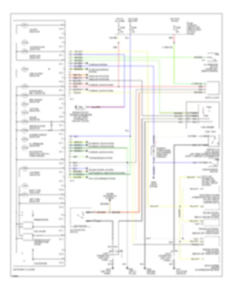
Instrument Cluster Wiring Diagram for Hyundai Tiburon 1998
List of elements for Instrument Cluster Wiring Diagram for Hyundai Tiburon 1998:
- "abs" system indicator
- "brake" system indicator
- "o/d off" indicator
- Anti-lock brakes system
- Brake fluid level sensor (left rear corner of engine compt, in brake fluid reservoir)
- C11
- C31
- Charge warning indicator
- Cruise control module (below center of dash)
- Cruise control system
- Cruise indicator
- Dash fuse box (below left side of dash, at kick panel)
- Data link connector (on left side of dash, above coin box)
- Digital clock
- Diode z01 (taped inside main harness, near dash fuse box)
- Door ajar indicator
- Electronic power steering control module (on left side of luggage compt)
- Engine control module (ecm) (behind left side of dash)
- Engine coolant temperature gauge
- Engine coolant temperature sender (on left rear of engine, on coolant outlet)
- Exterior lights system
- Fasten seat belt indicator
- Fuel gauge
- Fuel sender
- Fuel tank
- Fuse 10a
- Fuse 15a
- G131 (on intake manifold)
- G200 (left kick panel)
- G206 (center of dash)
- G904 (left c- pillar)
- Head lights system
- Headlights system
- High beam indicator
- Hot at all times
- Hot in on or acc
- Hot in on or start
- I01-1
- I01-2
- Instrument cluster
- Interior lights system
- Joint connector (left kick panel)
- Left turn indicator
- Light switch
- Low fuel indicator
- M58
- Malfunction indicator lamp (mil) "check engine"
- Multifunction switch
- Nca
- Oil pressure indicator
- Oil pressure switch (lower left rear of engine)
- Parking brake switch
- Power distribution system
- Red
- Right turn indicator
- Speedometer
- Srs "air bag" indicator
- Starting/charging system
- Tachometer
- Tailgate ajar indicator
- Transaxle control module (tcm) (behind left side of dash)
- Transmissions system
- Vehicle speed sensor (on speedometer head)
- Warning systems
 Čeština
 Dansk
Dansk Deutsch
 Ελληνικά
 English
 Español
 Suomi
Suomi Français
 Français
 עברית
עברית Hrvatski
 Magyar
 Italiano
 日本語
日本語 한국어
한국어 Nederlands
 Polski
 Português
 Português
 Română
 Русский
 Slovenčina
 Slovenščina
 Svenska
 Türkçe
 中文 (中国)
 English